Spectros T-Stat 2.0 User manual
Spectros Medical Devices Inc.
Rev B
T-STAT 2.0 User Manual
T-Stat 2.0
User Manual

Spectros Medical Devices Inc.
Page 2 of 44
Rev B
T-STAT 2.0 User Manual
T-Stat 2.0
Microvascular Tissue Oximeter
User Manual
Spectros Medical Devices. Inc.
2211 Norfolk St. #1110
Houston, TX 77098
www.spectros.com
T-Stat monitor and sensors are protected by the following patents issued:
US6711426; US7062306; US7427165
For Prescription Use Only

Spectros Medical Devices Inc.
Page 3 of 44
Rev B
T-STAT 2.0 User Manual
Table of Contents
Contents
A.
Safety Information..................................................................................................................................4
B.
Table of Symbols.....................................................................................................................................6
C.
About the Spectros T-Stat®Tissue Oximeter ..........................................................................................7
D.
Indications for Use ..................................................................................................................................8
E.
Principle of Operation.............................................................................................................................9
F.
Understanding T-Stat®Readings.............................................................................................................9
G.
Cautions and Notes...............................................................................................................................11
H.
Feature Layout......................................................................................................................................12
I.
Operation..............................................................................................................................................13
Monitoring Oxygenation.................................................................................................................13
Monitor Set-up and Oxygenation Measurement ...........................................................................13
Placement and Use of the Oral Sensor...........................................................................................15
Placement and Use of the Endoscopic Sensors..............................................................................16
Placement and use of the 1 cm Surface Sensor .............................................................................17
Placement and use of the 2.5 cm Surface Sensor ..........................................................................18
Changing the Alarm Settings...........................................................................................................19
Saving Data to Internal Disk............................................................................................................19
Data File Naming Convention: ........................................................................................................19
Moving Stored Data........................................................................................................................20
Changing Date and Time.................................................................................................................21
Checking Software Version Numbers .............................................................................................21
Instructions for Use of On-Call via Wi-Fi.........................................................................................22
Instructions for Use of On-Call via Verizon or ATT .........................................................................25
Verizon Access: ...............................................................................................................................25
AT&T Access:...................................................................................................................................26
J.
Care and Maintenance..........................................................................................................................27
Cleaning...........................................................................................................................................27
Storage and Transport ....................................................................................................................27
K.
Messages...............................................................................................................................................28
Appendix A: Measured Values.......................................................................................................................29
Appendix B: Sensor Specifications.................................................................................................................32
Appendix C: Self-Test and Errors ...................................................................................................................35
Appendix D: T-Stat®2.0 Specifications...........................................................................................................36
Appendix E: EMC Information .......................................................................................................................38
Appendix F: Warranty Information................................................................................................................41
Appendix G: Service and Disposal Information .............................................................................................43
References: ....................................................................................................................................................44

Spectros Medical Devices Inc.
Page 4 of 44
Rev B
T-STAT 2.0 User Manual
A.
Safety Information
Warnings
WARNING: Explosion hazard. Do not operate the monitor in the presence of flammable gases or
anesthetics, such as high concentrations of oxygen or nitrous oxide.
WARNING: Electric shock hazard. The monitor’s cover is to be removed only by qualified service
personnel. There are no user-serviceable parts inside.
WARNING: Use only the medical-grade AC power cord provided by the manufacturer. If in doubt
about the integrity of the mains supply connection, cease the operation of the monitor.
WARNING: Do not look directly into light source for extended periods of time.
WARNING: T-Stat sensors are designed for single use only and may not be re-used. Do not
autoclave or gas-sterilize any of the T-Stat sensors.
WARNING: Use only T-Stat sensors in conjunction with the T-Stat monitor. Connecting other
sensors may result in damage to the T-Stat monitor, or compromise its safety or performance.
WARNING: Do not autoclave, gas-sterilize, or immerse the T-Stat®monitor. This may create an
electric shock hazard, or damage internal components.
WARNING: Do not connect any accessories to the USB port on the rear panel of the monitor when the
system is in use on a patient other than the approved AT&T or Verizon modems.
WARNING: When monitoring on neonates or infants, check site every 4 hours for pressure necrosis
and change site every 24 hours.
WARNING: Reuse of Sterile Sensors can result in infection due to cross contamination.
WARNING: Sensors are designed for single use. Reuse can result in intermittent operation due to
contamination of the receiving connection in the T-Stat.
WARNING: When monitoring on adults, check site every 12 hours for pressure necrosis and change
site every 24 hours.
WARNING: Lithium Battery: Replacement by inadequately trained personnel could result in a HAZARD
(such as excessive temperatures, fire or explosion).
NOTE: Federal Regulations in the United States restrict the sale of this device to or on the order of
licensed medical practitioners.

Spectros Medical Devices Inc.
Page 5 of 44
Rev B
T-STAT 2.0 User Manual
Precautions
The prospective clinical value of measurements made with the T-Stat®Oximeter has not been
demonstrated in disease states. The T-Stat®Oximeter should not be used as the sole basis for
diagnosis or therapy. While normal StO2% ranges have been established, and tissue oximetry
has a demonstrated sensitivity to both hypoxemia and low-flow and no-flow ischemic states, the
prospective clinical value of StO2% measurements have not been established in disease states.
The T-Stat®Oximeter measures regional StO2% and may not reflect changes in oxygenation that
occur in regions outside of that monitored by the T-Stat®sensor.
The T-Stat®Oximeter, used alone at a single site, cannot differentiate between local and global
conditions.
Use of the T-Stat®during high-output shock states such as sepsis has not been evaluated. During
these conditions, central venous saturation may be normal or elevated, and the ability of T-
Stat(R) to detect tissue hypoxia is unknown.
Normal values, as read by the T-Stat®Tissue Oximeter, for liver and the small intestine have not
yet been established, as these readings are affected by organ pigments, and surface bile
(respectively).

Spectros Medical Devices Inc.
Page 6 of 44
Rev B
T-STAT 2.0 User Manual
B.
Table of Symbols
Caution: Consult this manual for a complete explanation
Electrical Shock Hazard
(AC). Alternating Current
Type BF Equipment
RX ONLY: US Federal regulations restrict the sale of this device to, or on the
order of licensed medical practitioners
Off/On
Audible Alarm Sounding
Do not re-use
No Latex
Battery Indicating Charge Level
Battery Exhausted- Shutdown will begin soon.
Battery Charging
Spectros Medical Devices Inc.
Page 7 of 44
Rev B
T-STAT 2.0 User Manual
C.
About the Spectros T-Stat®Tissue Oximeter
The complete system consists of:
(a) a durable, reusable monitor; and,
(b) a sterile, disposable patient sensor.
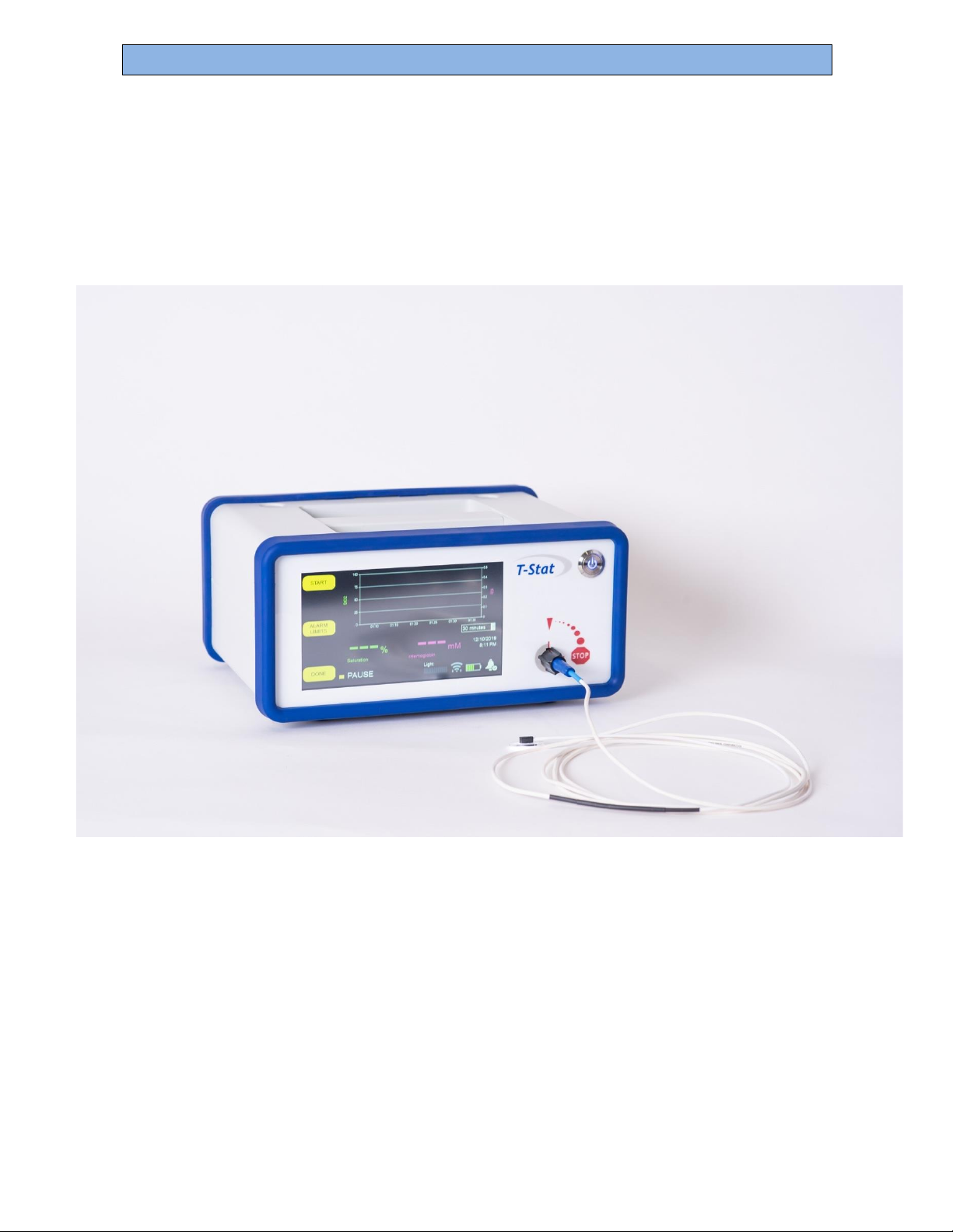
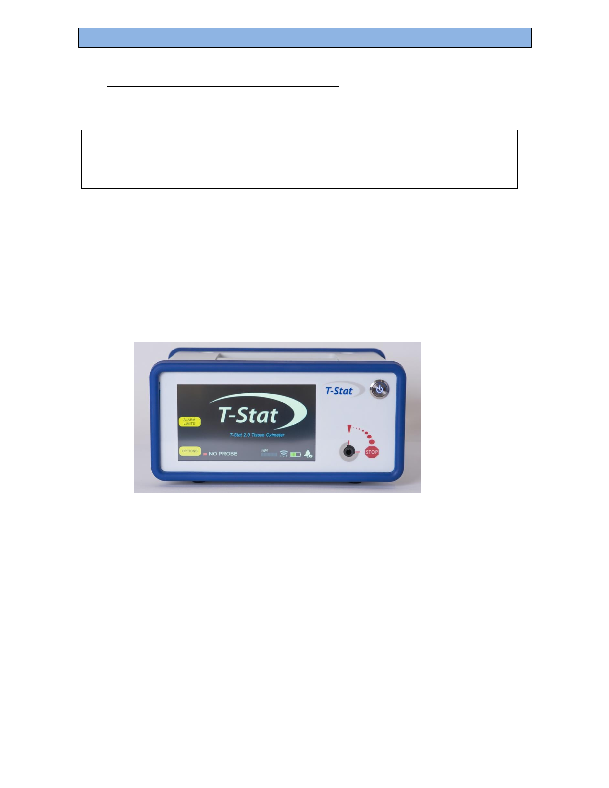
The monitor is a software-driven spectrophotometer, embedded CPU analyzer, isolated,
switching, AC-to-DC power supply, and touch-screen-based graphic user interface (GUI)
running under Windows 10 Embedded. A photograph of the monitor is shown below:
Figure 1 Photo of T-Stat®2.0
Each single-use patient sensor contains a visible light source for illuminating the tissue, and
glass optical fibers for transmitting light remitted from tissue, along the sensor fiber, and back
to the monitor.
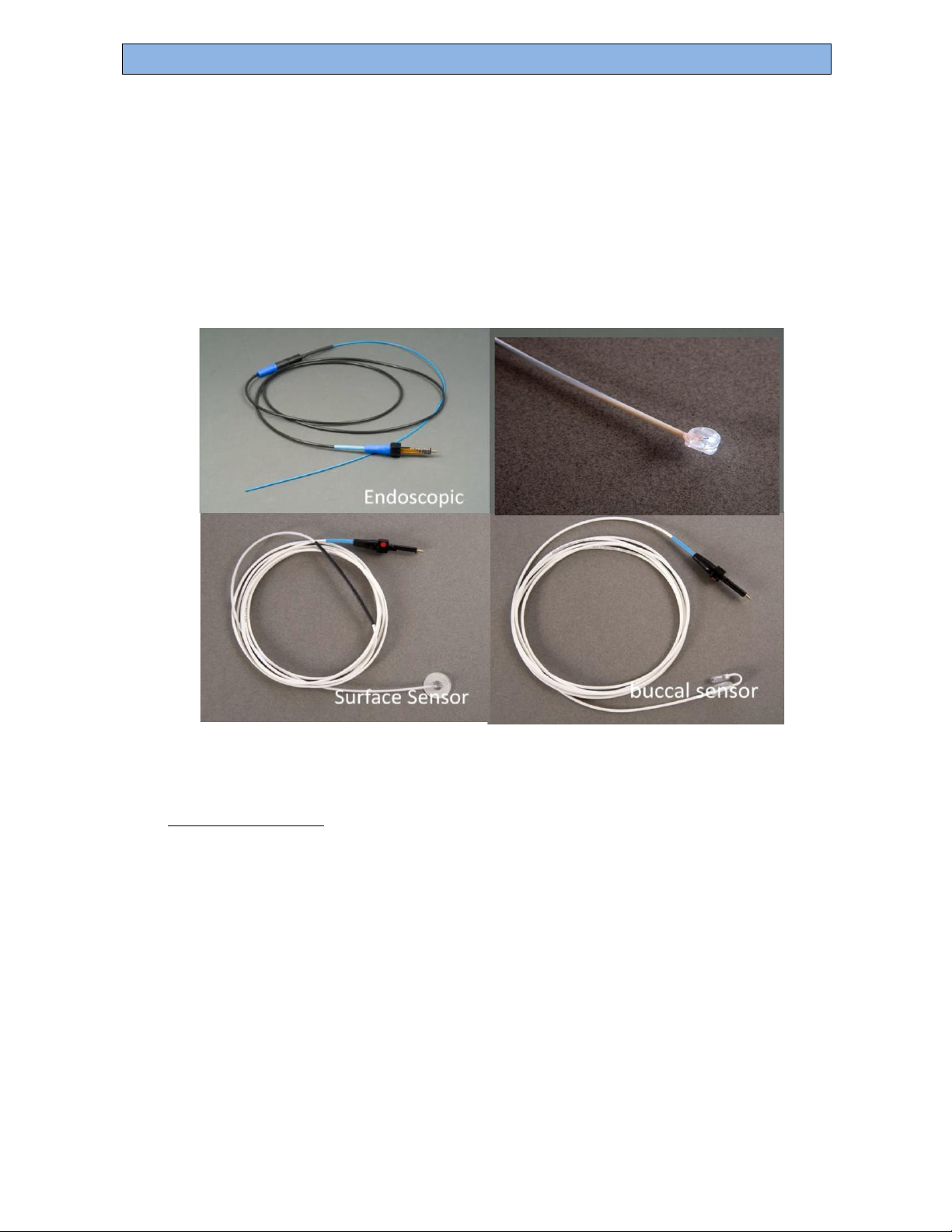
There are five different T-Stat®sensor sensors available. The clinical choice of sensor is
determined by the target site of monitoring, either oral (buccal), endoscopic (via endoscopy),
or surface (Skin- 2 sizes).
The T-Stat®Microvascular Tissue Oximeter provides a continuous, noninvasive, and localized
measurement of the microvascular hemoglobin oxygen saturation, sensitive to regional and
global reduced-flow or no-flow ischemia, as demonstrated in peer- reviewed human clinical
studies.
Spectros Medical Devices Inc.
Page 8 of 44
Rev B
T-STAT 2.0 User Manual
Monitoring is achieved by attaching the connector end of the selected sensor to the monitor
and placing the patient end of the selected sensor near, on, or into the target tissue to be
studied, depending upon the site selected.
A view of the patient end of each sensor is shown below:
Figure 2 Photographs of T-Stat®2.0 Sensors
D.
Indications for Use
The Spectros T-Stat®2.0 Microvascular Tissue Oximeter is intended for use as an adjunct
monitor of the localized hemoglobin oxygen saturation of blood in the microvascular tissue
spaces (StO2%) in infants, children, or adults at risk for reduced-flow and no-flow ischemic
states.
The prospective clinical value of measurements made with the T-Stat®Oximeter has not
been demonstrated in disease states. The T-Stat®Oximeter should not be used as the sole
basis diagnosis or therapy.
For prescription use only.
1 CM Surface Sensor
2.5 CM

Spectros Medical Devices Inc.
Page 9 of 44
Rev B
T-STAT 2.0 User Manual
E.
Principle of Operation
The basis for operation for the T-Stat®2.0 Tissue Oximeter is that hemoglobin in its various
forms (oxy-, deoxy-, met-, carboxy-) has unique spectroscopic properties that allow StO2%
to be determined based on measurements of the spectral characteristics of the reflectance of
light from tissue. The Spectros T-Stat®uses broadband, multi-wavelength illumination and
monitoring to determine the relative amount of oxygenated and deoxygenated hemoglobin
in the microvascular tissue spaces. StO2% is then defined as the percentage of hemoglobin in
the oxygenated form as compared to the total hemoglobin in both oxygenated and
deoxygenated forms. The broadband spectral approach also allows for measurement of
tissue characteristics, ie lipid and water concentration. These characteristics can be used to
make a determination that the site or region where the sensor is placed is in fact looking at
components that comprise normal tissue. The software provides a displayed warning of “no
tissue” when it detects spectral parameters outside normal tissue ranges in order to alert the
doctor to verify the sensor placement.
F.
Understanding T-Stat®Readings
The T-Stat®Tissue Oximeter measurements differ from conventional pulse oximetry in
several important ways:
Capillary-weighted
Hemoglobin oxygen saturation of blood in the microvascular tissue, is typically lower than
pulse oximetry saturation (SpO2%) and arterial saturation (SaO2%). Whereas pulse
oximetry measures arterial saturation, tissue oxygenation is capillary-weighted, and
estimates the hemoglobin oxygen saturation at the site of tissue oxygen extraction. Tissue
optical saturation is thus responsive to changes in oxygenation of the tissue itself, whether
caused by changes in arterial oxygenation (hypoxemia) or by changes in blood flow
(reduced-flow or no-flow ischemia).
Non-pulsatile
Unlike pulse oximetry, a pulse is not required for the measurement to be made. Therefore, the T-
Stat®Tissue Oximeter continues to measure during low-perfusion, hypotension, or asystole.
Normal Values Differ
Hemoglobin oxygen saturation of blood in the microvascular tissue spaces (StO2%) typically
runs much closer to venous saturation (SvO2%) than to arterial saturation (SaO2%). Tissue
oxygen saturation StO2% for some tissues has been established. While reference ranges for
human use have not been recognized in health and disease, measured and published values
of StO2% for many tissues are typically 71% +/- 3%, or a 95% confidence interval of 65%
- 77% (see Table 1, below).

Spectros Medical Devices Inc.
Page 10 of 44
Rev B
T-STAT 2.0 User Manual
Table 1 Normal Range of Oxygenation Values for pulse oximetry, central venous
sampling, and VLS tissue oximetry
Value
Normal
Range
Description
SaO2%
95-100%i,ii
Arterial hemoglobin saturation. Commonly
estimated by Pulse Oximetry.
SvO2%
65-75%iii,iv
Venous hemoglobin saturation. Commonly
estimated by Central Venous Catheter
sampling.
StO2%
65-77%*
Tissue optical hemoglobin saturation. A
capillary-weighted value that is typically
much closer to venous saturation than to
arterial saturation.
*Normal values, as read by the T-Stat ® Tissue Oximeter, for liver and the small intestine have not yet been
established, as these readings are affected by organ pigments, and surface bile (respectively).
Sensitive to Hypoxemia
During hypoxemia (low arterial saturation), when oxygen delivery to the tissue is reduced,
both pulse oximetry and tissue optical oximetry report low values.
Sensitive to low-flow or no-flow Ischemia
Reduced blood flow ischemic states are detected by tissue oxygen saturation (StO2%) but are
not detected by pulse oximetry. During reduced blood flow ischemia (such as from tissue
ablation, thrombosis, or cardiac failure), the arterial saturation remains unchanged, but the
reduced blood flow results in a lowered tissue oxygenation due to a higher fractional
extraction of delivered oxygen to the capillaries.
Estimates Blood Content
T-Stat®estimates and displays the relative hemoglobin of the tissue (rHemoglobin) in μmol/L.
Pulse oximetry is insensitive to this value, registering only the changes in blood content during
arterial pressure changes between systole and asystole rather than the total blood signal. This
signal may vary with depth of the measurement, and therefore is dependent upon the sensor
used, as well as has a high noise induced by scattering. rHemoglobin values are +/- 20% and
include total hemoglobin plus myoglobin.

Spectros Medical Devices Inc.
Page 11 of 44
Rev B
T-STAT 2.0 User Manual
G.
Cautions and Notes
1. Capillary-weighted tissue oxygenation differs from arterial oxygenation as measured by
pulse oximetry. Tissue oxygenation (StO2%) is influenced by arterial blood oxygenation
(SaO2%), as well as by blood flow and blood hemoglobin content, and does not require
a pulse in order to obtain a measurement.
2. Measured values are affected by blood in direct contact with air. Care must be taken to
ensure the measured surface is devoid of free, extravasated hemoglobin, such as
introduced by trauma or surgery. Thin mucosa, such as the intestinal wall, can also absorb
oxygen directly through the mucosa, and read as more highly oxygenated, during open
surgical procedures.
3. Tissue oxygenation is affected by tissue compression, which locally reduces blood flow and
produces local ischemia. Care must be taken that local tissues are not made artificially
ischemic by direct pressure from the sensor.
4. T-Stat®sensors are designed for single human use only. Do Not Re-sterilize and Do Not
Reuse sensors in human subjects.
5. Normal values, as read by the T-Stat®Tissue Oximeter, for the liver and the small intestine
have not yet been established, as these readings are affected by organ pigments, and
surface bile (respectively).

Spectros Medical Devices Inc.
Page 12 of 44
Rev B
T-STAT 2.0 User Manual
H.
Feature Layout
The T-Stat®Tissue Oximeter parts and features are illustrated below:
Figure 3 T-Stat®2.0 Physical Layout
Menu buttons
1. Graph (StO2%,rHb)
2. Sensor Probe Socket
3. Saturation
4. Relative Hemoglobin (rHb)
5. Color Status Dot and Message
6. On/Off Button
1. Power Switch
2. Electrical Supply
3. USB Port
4. Wi-Fi Antenna
Port
1
4
2
3

Spectros Medical Devices Inc.
Page 13 of 44
Rev B
T-STAT 2.0 User Manual
I.
Operation
Monitoring Oxygenation
In order to use the T-Stat®Tissue Oximeter, the monitor is placed 2meters or
less from the bedside (limited only by the length of the sensor cable, not by any
fundamental limitation of transmission). A disposable sensor is then placed at
the target tissue site, either oral (buccal), skin, or through an endoscope. These
procedures are described below.
Monitor Set-up and Oxygenation Measurement
1. Turn the T-Stat®monitor unit on (make sure the rear panel power switch is
turned to the “on” position).
2. The monitor automatically performs a self-test that requires about 1 minute
to complete.
3. Remove the T-Stat®sensor from its sterile packaging, using either
clean or sterile technique as required given the site of
measurement.
4. Sensor can be plugged in at any time. Attach the connector on the
sensor to the connection port on the monitor, located to the lower
right of the monitor display. Align the red line on the sensor connector
with the red arrow on the front panel (12:00), insert the connector
into the connection port until it hits a hard stop and rotate ¼- turn
clockwise to lock in place (3:00). Sensor identification and calibration
will begin automatically when sensor is plugged in.
5. When the T-Stat completes its self-test and senses a sensor it reads
the calibration data from the sensor and goes to the start screen.
6. Place T-Stat®sensor on desired location for patient monitoring (see
the following section for the procedures for placement of each of the
three different sensor types).
7. Push START to collect and display data.
8. Push PAUSE to temporarily stop monitoring (data will be retained on
the existing screen.)
9. Chart display range can be changed by pressing the pull-down menu to
the lower right of the chart. Ranges available are 20min, 1hr, 12hr, 1
day, 2 day, 3 day, 4 day and 5 day.
10. Measurement can be started and stopped as needed by pressing PAUSE.
11. When finished monitoring, press PAUSE then DONE Selecting DONE will close the

Spectros Medical Devices Inc.
Page 14 of 44
Rev B
T-STAT 2.0 User Manual
current data file, store it in the internal memory and no longer display this file on the
visual screen chart.
12. When finished monitoring remove from the patient and discard sensor.
13. Make sure to turn the power off from the front of the monitor. If you wish to keep
the monitor charging, make sure it is plugged in, the back power switch is on and
the front power button is off.
Spectros Medical Devices Inc.
Page 15 of 44
Rev B
T-STAT 2.0 User Manual
Placement and Use of the Oral Sensor
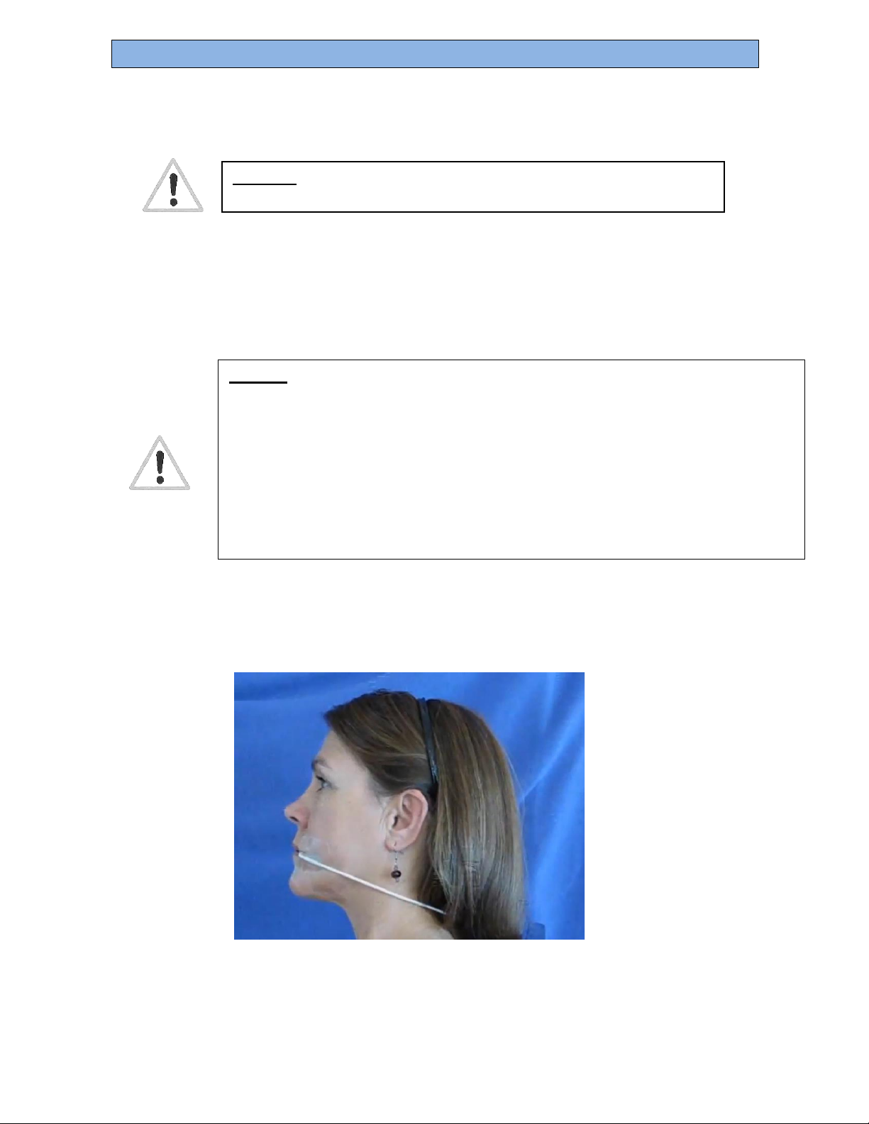
The oral sensor is placed in the following steps:
1. The sensor is connected to the monitor, and then the cable is routed to comfortably
place the sensor alongside either the left or right cheek.
2. The patient’s mouth is opened, and the illuminated portion of the sensor is placed
inside the mouth, with the cable portion placed on the outside of the cheek.
3. The sensor cord is positioned along the angle of the jaw, near or behind the ear. The
sensor cord may be taped to the skin, near the angle of the jaw or behind the ear if
desired, to stabilize the sensor.
Figure 4: Placement of the Oral Sensor in an Adult
The sensor can be placed against either cheek, left or right. Note that the sensor end is
located against the inner oral mucosa.
Caution:
—
Ensure that the illuminated portion of the sensor is not in contact with the cheek.
Excess pressure on the inner cheek at the sensor site can alter local blood flow
and result in lower measured local saturation.
—
Ensure that the inner cheek surface is free of surface blood. Free blood
becomes well oxygenated upon exposure to air and result in a higher
measured saturation. A monitor warning of “Excess Blood” or a saturation
above 95% suggests this condition.
Caution: If pouch integrity is compromised prior to removal, discard
sensor. Possibility of contamination presents risk to patient

Spectros Medical Devices Inc.
Page 16 of 44
Rev B
T-STAT 2.0 User Manual
Placement and Use of the Endoscopic Sensors
The endoscopic sensor is placed during an endoscopy procedure in the following steps:
1. The connector end of the endoscopic sensor is connected to the monitor, and the cable is routed
to where the endoscopist is located.
2. The patient end of the endoscopic sensor is inserted into a 2 mm minimum diameter endoscope
accessory channel, and advanced until visualized by the endoscopist through the viewing channel
of the endoscope.
3. The endoscopic sensor is brought into proximity of the tissue to be measured. A white VLS
spot is seen on the tissue, for confirmation purposes. The endoscopic VLS sensor is a non-
contact sensor. All that is required for measurement is a view of the mucosal tissue to be
monitored.
The placement of the endoscopic sensor is illustrated in the following figure:
Figure 6 Placement of the Endoscopic Sensor
Caution:
–Ensure that the illuminated portion of the endoscopic sensor is not in contact
with the mucosal tissue. Excess pressure on mucosal tissue at the sensor site
can alter local blood flow and result in lower measured local saturation. A
visual confirmation of sensor positioning during measurement will avoid this
condition.
–Ensure that the mucosal surface is free of surface blood. Free blood becomes
well oxygenated upon exposure to air and will cause a higher measured
saturation. A monitor warning of “Excess Blood” or asaturation above 95%
suggests this condition.
Caution:
If pouch integrity is compromised prior to removal, discard sensor.
Possibility of contamination presents risk to patient

Spectros Medical Devices Inc.
Page 17 of 44
Rev B
T-STAT 2.0 User Manual
Placement and use of the 1 cm Surface Sensor
Preparation
–Assure skin area to be measured is clean and free of blood.
–Do not apply to open wound.
Placement
1. Remove T-Stat®Surface Sensor from Sterile Package
2. Insert the connector end of the sensor into the T-Stat VLS Monitor, aligning the red line on the
sensor connector nut and the red arrow at 12:00 on the monitor, then rotating one quarter turn
clockwise after insertion (to the locked position.). When locked into position, the white light sensor
will illuminate and will automatically go through recognition and calibration. If this does not
happen, this step is incomplete.
3. Hold sensor flat on skin surface being careful not to apply pressure, so as to cause local ischemia.
FIGURE 7 - 1 cm surface sensor
Caution:
Local pressure may cause local ischemia.
Move sensor to new site every 12 hours
Caution: If pouch integrity is compromised prior to removal, discard
sensor. Possibility of contamination presents risk to patient

Spectros Medical Devices Inc.
Page 18 of 44
Rev B
T-STAT 2.0 User Manual
Placement and use of the 2.5 cm Surface Sensor
Preparation
–Assure skin area to be measured is clean and free of blood.
–Do not apply to open wound.
Placement
Remove T-Stat®Surface Sensor from Sterile Package.
1. Insert the connector end of the sensor into the T-Stat VLS Monitor, aligning the red line on the sensor
connector nut and the red arrow at 12:00 on the monitor, then rotating one quarter turn clockwise
after insertion (to the locked position.). When locked into position, the white light sensor will
illuminate and will automatically go through recognition and calibration. If this does not happen, this
step is incomplete. Remove the white sticker tape from the face of the surface sensor disk.
2. Place sensor flat on skin surface being careful not to apply too much pressure so as to not cause local
ischemia.
3. Surgical tape or Tegaderm can be used to help make sure the sensor stays in place.
FIGURE 8. Placement of 2.5 cm Surface Sensor
Caution: Local pressure may cause local
ischemia. Move sensor to new site every 12
hours
Caution: If pouch integrity is compromised prior to removal, discard
Sensor. Possibility of contamination presents risk to patient

Spectros Medical Devices Inc.
Page 19 of 44
Rev B
T-STAT 2.0 User Manual
Changing the Alarm Settings
A flashing alarm can be set to display on the screen if saturation rises above or
falls below a set value. This can be done on the main menu, which appears after
power up, before plugging in the sensor, or can be reached by pausing the
measurement and pressing “Done Monitoring”
1. The alarm limit screen is selected by pressing ALARM Limits .
2. Change the saturation limits using the +/- buttons until the desired limits are
shown. The default is set to 20% low and 90% high.
3. Auditable alarms can be silenced permanently by pressing
DISABLE ALARM
4. When done press HIDE ALARM SCREEN
When setting the alarms, the real-time values measured continue to be
displayed at the bottom of the screen.
Saving Data to Internal Disk
1. From the main screen, select
2. To save/discard future displayed results select “Save Patient Results”
3. To save/discard future raw data select/deselect “Save RAW DATA”
4. To save/discard future intermediate calculations select/deselect “Keep
Calculations”
5. When done select OPTION DONE
Data File Naming Convention:
Files are automatically named using the date and monitor serial number, as
follows:
YYYY_MM_DD_SerialNumber_####.
For example, the second study on January 25, 2002 would be saved under the name:
2002_01_25_TS2.0D1000A_0002

Spectros Medical Devices Inc.
Page 20 of 44
Rev B
T-STAT 2.0 User Manual
In the example above, the T-Stat®device serial number is: TS2.0D1000A.
File Folders:
T-Stat®files are transferred to two folders: Data and Results.
Data Files:
T-Stat®produces 3 types of output files in Windows PC format:
Type: Save As: Where
Saved:
For export, files are saved as text, and can be opened using Word,
WordPad, NotePad or Excel on a PC running under Windows.
Moving Stored Data
When data are stored (see above), they are saved to an internal T-Stat®
Oximeter disk. Moving stored data copies the data to a disk and erases the data
stored in the T-Stat®system. Stored data can be transferred to a Zip™ or other
USB Storage Device as follows:
1. Connect storage device to the USB data port (on rear panel of monitor).
2. From the main screen, select OPTIONS
3. Select TRANSFER DATA There will be a brief pause before copying data is complete
4. Wait until copying is done and “OK to Remove Disk.” is displayed before removing
the disk. Press DONE WITH OPTIONS to complete. If the disk becomes full, copying
will stop and a message will be displayed describing the number of files copied
and the number remaining to be copied. The remaining files can be copied by
inserting another memory device and repeating the steps above.
Data Files:
ID files (*.tid)
Spectros\Data
Results Files:
TIR files (*.tir)
Spectros\Results
Intermediate Files:
File Format:
TII files (*.tii)
Spectros\Results
Other manuals for T-Stat 2.0
1
Table of contents


