Heraeus Heracast EC User manual
Heracast EC
GB Operating instructions
Heracast EC
Dateiname: W10095_66044668_02_BA_Heracast_EC_GB_V4_X3
SAP-Nr: Version
66044668 02
HK-Toolbox-Nr:
W10095
Format: Falzmaß:
420 x 280 mm 210 x 280 mm
Projektmanager:
Michael Helken
HKG-Version:
V4, 3.AK
Datum HKG Freigabe am
01.10.2013 07.10.2013
HKG-Layout 66044668_02_BA Heracast EC_GB
EURO / Pantone Sonderfarben Druckverfahren: Digitaldruck
C M Y K varnish DieCut var.Data
https://stomdevice.ru - стоматологическое изуботехническое оборудование сдоставкой по России иСНГ

https://stomdevice.ru - стоматологическое изуботехническое оборудование сдоставкой по России иСНГ

Operating instructions
Heracast EC
- 3 -
GB
DE
GB
FR
ES
IT
PT
NL
SE
DK
NO
FI
GR
Table of contents
1 Scope of applicability ................................................................................................................................... 5
1.1 General ............................................................................................................................................................ 5
1.2 Description and type of machine ........................................................................................................................ 5
1.3 EU Statement of conformity ............................................................................................................................... 5
2 Instructions on using the unit safely ............................................................................................................... 6
2.1 Explanation of Symbols ..................................................................................................................................... 6
2.2 Transport damage ............................................................................................................................................. 6
2.3 Operator‘s obligations ........................................................................................................................................ 6
2.4 Unit book ......................................................................................................................................................... 6
2.5 Safety information ............................................................................................................................................ 6
3 Use in accordance with specifications ............................................................................................................ 7
3.1 Working rules ................................................................................................................................................... 8
4 Scope of delivery / consumables set ............................................................................................................... 8
4.1 Scope of delivery ............................................................................................................................................... 8
4.2 Accessories not included in the scope of delivery ................................................................................................. 8
4.3 Original equipment Set ...................................................................................................................................... 8
5 Structure and function .................................................................................................................................. 9
5.1 Control and display elements .............................................................................................................................. 9
5.2 Partial view open chamber ............................................................................................................................... 10
5.3 Partial view cooling water ................................................................................................................................. 11
5.4 Partial view inlet and power connections ........................................................................................................... 12
6 Location and installation ............................................................................................................................. 12
6.1 Transport ........................................................................................................................................................ 12
6.2 Unpacking ...................................................................................................................................................... 12
6.3 Set-up ........................................................................................................................................................... 13
6.4 Mains connection ............................................................................................................................................ 13
6.5 Compressed air supply ..................................................................................................................................... 13
6.6 Vacuum air connection ..................................................................................................................................... 14
6.7 Filling the cooling system ................................................................................................................................ 14
6.8 Room ventilation ............................................................................................................................................. 14
7 Operations ................................................................................................................................................. 14
7.1 Putting into operation ...................................................................................................................................... 14
7.2 Putting out of operation ................................................................................................................................... 15
7.3 Errors and causes ........................................................................................................................................... 15
7.4 Manual unlocking of casting chamber ............................................................................................................... 17
8 Working with Heracast EC ........................................................................................................................... 18
8.1 Controls for operating ...................................................................................................................................... 18
8.1.1 Icons in the status display ............................................................................................................................... 18
8.2 Casting Menu ................................................................................................................................................. 19
8.3 Setup Menu ................................................................................................................................................... 19
8.4 Info Menu ....................................................................................................................................................... 20
8.5 Error History ................................................................................................................................................... 20
9 Melting and casting .................................................................................................................................... 20
9.1 General .......................................................................................................................................................... 20
9.2 Suitable investment materials .......................................................................................................................... 20
9.3 Premelting ..................................................................................................................................................... 20
9.4 Casting .......................................................................................................................................................... 21
9.4.1 Graphite insert ............................................................................................................................................... 21
9.4.2 Ceramic crucibles ........................................................................................................................................... 21
https://stomdevice.ru - стоматологическое изуботехническое оборудование сдоставкой по России иСНГ

- 4 -
GB
DE
GB
FR
ES
IT
PT
NL
SE
DK
NO
FI
GR
10 Alloys ........................................................................................................................................................ 21
10.1 Gold casting and high gold content ceramic bonding alloys
Universal and silver palladium alloys ................................................................................................................ 21
10.2 Reduced precious metal ceramic bonding and palladium-based alloys ................................................................. 22
10.3 CoCr partial denture and non-precious metal alloys ............................................................................................ 22
10.4 Titanium and aluminium-containing alloys ......................................................................................................... 22
11 Maintenance .............................................................................................................................................. 23
11.1 Maintenance and care ..................................................................................................................................... 23
– daily ........................................................................................................................................................... 23
– weekly (or after 100 castings) ....................................................................................................................... 23
– annually (or after 3.000 castings) .................................................................................................................. 23
– after 10.000 casting or after 3 years .............................................................................................................. 23
11.2 Tests ............................................................................................................................................................. 23
11.3 Maintenance .................................................................................................................................................. 24
11.4 Disposal ......................................................................................................................................................... 24
11.5 Disposal of old equipment according to WEEE ................................................................................................... 24
12 Technical data ........................................................................................................................................... 24
12.1 Operating conditions ....................................................................................................................................... 25
12.2 Rating plate ................................................................................................................................................... 25
12.3 Circuit diagrams compressed air ....................................................................................................................... 25
12.4 Circuit diagrams water circulation .................................................................................................................... 26
13 Recommendations for casting ..................................................................................................................... 26
14 Control information .................................................................................................................................... 28
15 Service ...................................................................................................................................................... 29
15.1 Service agents / Contact in the countries ........................................................................................................... 29
16 Document history ....................................................................................................................................... 30
https://stomdevice.ru - стоматологическое изуботехническое оборудование сдоставкой по России иСНГ
Operating instructions
Heracast EC
- 5 -
GB
DE
GB
FR
ES
IT
PT
NL
SE
DK
NO
FI
GR
1 Scope of applicability
1.1 General
Combilabor®is a registered trademark of Heraeus Kulzer GmbH. Author f48618
These working instructions apply to:
Order-No. Type Features Date
66041213 Heracast EC 2013-10 / 66044668/02
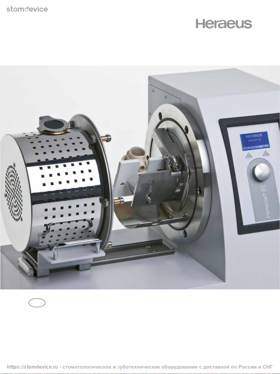
1.2 Description and type of machine
Type of machine Serial-No.
Induction vacuum-pressure casting machine Heracast EC 2010-01-0001 ff.
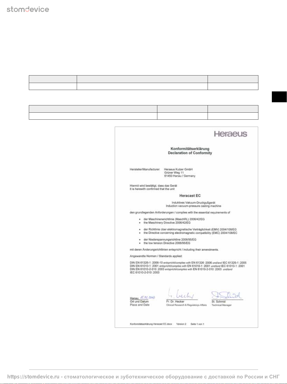
1.3 EU Statement of conformity
Herewith we, Heraeus Kulzer GmbH,
Grüner Weg 11, 63450 Hanau (Germany),
confirm that the following unit due to its
intended use and the version marketed by us
corresponds to the relevant basic safety and
health requirements of the EC guideline.
This statement will become invalid in case
of any modification of the unit that is not
coordinated with us.
https://stomdevice.ru - стоматологическое изуботехническое оборудование сдоставкой по России иСНГ

- 6 -
GB
DE
GB
FR
ES
IT
PT
NL
SE
DK
NO
FI
GR
2 Instructions on using the unit safely
2.1 Explanation of Symbols
Symbol Accompanying word(s) Explanation
CAUTION Safety-relevant paragraphs and sections in these working instructions
have been marked with this symbol.
NOTE Information within the working instructions on the
optimum use of the unit.
HOT SURFACE Hot surface.
Risk of getting burned.
HIGH FREQUENCY Caution high frequency.
Not to be used by persons with pacemakers.
WARNING Warning:
Caution High frequency.
DISCONNECT FROM MAINS Danger of electric shock when unit is opened.
Unplug the unit before opening it.
CHANGE Important:
Changes have been made to this paragraph.
Please read carefully.
Registration certificate according to the ministry of health
of the Russian federation.
2.2 Transport damage
Please check the unit for transport damage and, if necessary, report the damage to the forwarder within 24 hours
after receiving the unit.
Under no circumstances, work with a damaged machine.
2.3 Operator‘s obligations
In addition to complying with the statutory regulations specified by the manufacturer, the operator must ensure the statutory
obligations are observed and implemented at the working place, i.e. he must train his personnel and comply with industrial safety
legislation and any other regulations or laws in force.
For working at and with the machine, the operator must draw up written instructions in understandable form and give these
to his employees in their own language. These instructions must be based on the operating manual and written in light of the
work to be performed.
2.4 Unit book
We recommend you keep a unit book. All tests as well as all essential works (e.g. repair work, modifications)
must be documented in this book.
2.5 Safety information
With these laboratory units the safety concerning the protection of persons, the environment and the material to be processed
mainly depends on the behavior of the persons operating the unit.
Prior to operation read the working instructions carefully, adhere to the information provided in order to avoid errors and damage,
in particular damage to the health.
In addition to the information in these working instructions, relevant national laws and guidelines must be observed for setting up
and operating this unit (technical connection requirements of the electrical supply companies, etc.).
https://stomdevice.ru - стоматологическое изуботехническое оборудование сдоставкой по России иСНГ

Operating instructions
Heracast EC
- 7 -
GB
DE
GB
FR
ES
IT
PT
NL
SE
DK
NO
FI
GR
HIGH FREQUENCY
Not to be used by persons with pacemakers Read working instructions prior to use! We cannot accept any guarantee
claims or assume liability if the machine is used for other purposes as stated or for damage resulting from non-
compliance with these working instructions!
HOT SURFACE
The metal surface around the casting chamber heats up during continuous operation.
Do not touch this surface.
When casting and in particular when handling melted metal face guards, gloves and aprons must be worn.
Cleaning must always be carried out when the unit is cool.
WARNING
This symbol warns of the dangers of electric voltage. In the case of non-compliance the result of an electrical shock
with all known effects can be death. When inspecting the housing cover this safety symbol is visible on the free
surface on the operating unit. Please observe the safety instructions when carrying out servicing.
Works at the electrical equipment of the unit must only be performed by the authorised Heraeus service and in the
safe condition (voltage cleared).
CAUTION
Power cable and plug must be checked for damage prior to operation.
If any damage exists, the unit must not be connected to the mains.
A damaged mains connecting cable may only be replaced by a mains connecting cable of the same type.
3 x 1.0 mm², H05RR-F, black, 155°C, central plug, straight / power connector.
NOTE
Due to the waste gases released during working, adequate ventilation must be provided.
Works at the electrical equipment of the unit may only be performed by adequately trained service companies and in the safe
condition (voltage cleared).
Only permissible original spare parts must be used. The use of different parts holds unknown risks and must be avoided
at any rate.
Proper function and safety of the unit are only guaranteed if the required tests, maintenance and repair work have been
performed by Heraeus Kulzer service agents or by personnel adequately trained by the manufacturer.
Heraeus Kulzer will not accept any liability for damage to the unit resulting from inexpert repair which has not been performed
by Heraeus service agents or if no original spare parts / accessory parts have been used during the exchange of these parts.
3 Use in accordance with specifications
The induction casting machine Heracast EC is a laboratory unit for casting all precious metal and almost all non-precious and
CoCr partial denture alloys for dental applications with a liquidus temperature of 500 °C up to > 1600 °C.
The unit is not suitable or intended for casting pure titanium or beryllium-containing alloys!
CAUTION
Processing of beryllium-containing alloys is hazardous to health!
Casting of these alloys is performed at the user‘s risk! Heraeus Kulzer GmbH will not accept any liability for any health
damage that may have been caused by casting such alloys!
Casting of titanium- or aluminium-containing alloys is performed in special working steps.
See paragraph 10.4 Titanium and aluminium-containing alloys.
Precision castings with alloy quantities of up to 130 g in the graphite crucible and 100 g in the ceramic crucible are possible.
Alloy quantity for CoCr partial denture and non-precious metal bonding alloys in the ceramic crucible: up to 60 g.
NOTE
We recommend the exclusive use of original Heraeus Kulzer crucibles which are especially made for this type
of application. The use of other materials voids guarantee claims in case of damage to the unit or the molten material.
Due to various possible causes for bad castings results, we do not grant any guarantee for such cases.
https://stomdevice.ru - стоматологическое изуботехническое оборудование сдоставкой по России иСНГ

- 8 -
GB
DE
GB
FR
ES
IT
PT
NL
SE
DK
NO
FI
GR
3.1 Working rules
CAUTION
▀Personal protective equipment such as hand, face and body protection must be worn;
jewellery must be taken off prior to working.
▀Normally, the unit is suitable to be set up and operated in the following fields: Commercial and industrial
laboratories, schools, universities, hospitals, etc. The unit has been designed for continuous operation.
▀The pressure control is technically set to 3.5 bar on the unit and by means of a safety valve set to
a pressure of 3.7 bar.
CAUTION
Do not use the unit for the following activities:
▀The unit must not be used for melting and casting beryllium-containing alloys (hazardous to health!).
▀Do not use the unit for melting, drying or thermal treatment which may lead to the release of combustible
gases and vapours which burn with air or which may form a hazardous, injurious or explosive mixture.
▀The unit is not suitable for thermal treatment of hazardous or health-hazardous materials
(e.g. dusts, fibres, liquids, solids).
▀The unit must not be used to heat up food.
4 Scope of delivery / consumables set
Check that all components are in perfect condition on delivery of the machine.
If you wish to make a complaint, contact your supplier.
4.1 Scope of delivery
1 x Heracast EC, Operating instruction, test certificate
1 x Key for casting ring holder
1 x Pressure hose 13 mm, incl. 2 hose clamps and a socket 13 mm
2 x Door signs
Caution! High frequency. ”Not to be used by persons with pacemakers”
HIGH FREQUENCY
Attach the supplied adhesive symbols ”Not to be used by persons with pacemakers” to all entrances
to the unit service room.
4.2 Accessories not included in the scope of delivery
Vacuum pump: CL-P Typ 7, 230 Volt, 50 / 60 Hz Order-No. 66002450
4.3 Original equipment Set
1 x Small alloy spoon
1 x Box cont. small melting powder pellets
1 x Acrylic sprue canal aid
1pack 6 pcs ceramic crucibles for CL-IG / IM / I95 / Heracast iQ / EC
1pack 6 pcs ceramic crucibles NPM-crucibles for CL-IG / IM / I95 / Heracast iQ / EC
1 x Crucible box CL-IG / IM / I95 / Heracast iQ / EC
1pack 10 pcs graphite inserts for CL-IG / IM / I95 / Heracast iQ / EC
3 x each Casting ring (X3, X6, X9)
1 x each Cone former (X3, X6, X9)
https://stomdevice.ru - стоматологическое изуботехническое оборудование сдоставкой по России иСНГ
Operating instructions
Heracast EC
- 9 -
GB
DE
GB
FR
ES
IT
PT
NL
SE
DK
NO
FI
GR
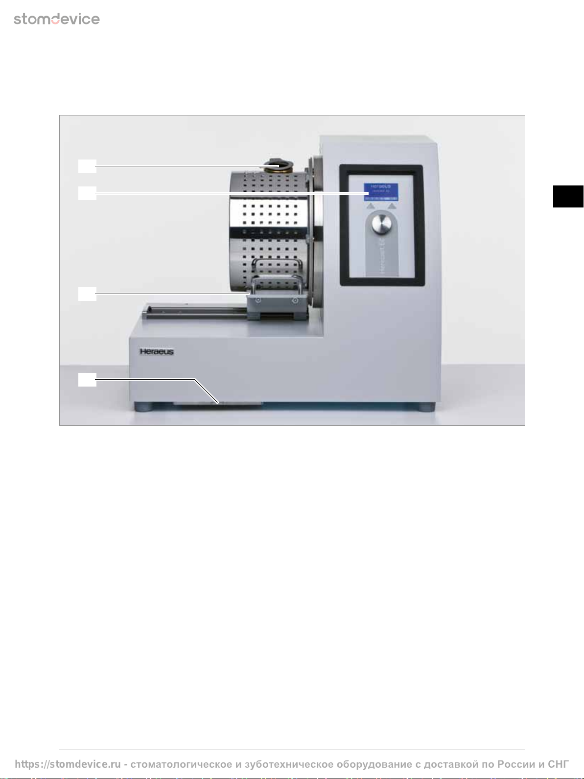
5 Structure and function
5.1 Control and display elements
1
2
3
4
1Viewing glass – casting chamber
2Graphic display with control elements
3Locking lever – casting chamber
4Filter cover – air supply
https://stomdevice.ru - стоматологическое изуботехническое оборудование сдоставкой по России иСНГ

- 10 -
GB
DE
GB
FR
ES
IT
PT
NL
SE
DK
NO
FI
GR
5.2 Partial view open chamber
5
6
7
8
9 10 11 12 13 14
5Viewing glass – casting chamber
6Ceramic crucible
7Shielding plate
8Adjustable casting ring holder
9Locking lever – casting chamber
10 Collecting plate
11 Screw for adjustable casting ring holder
12 Clamping device for casting ring
13 Interactive buttons
14 Turnable push-knob
https://stomdevice.ru - стоматологическое изуботехническое оборудование сдоставкой по России иСНГ

Operating instructions
Heracast EC
- 11 -
GB
DE
GB
FR
ES
IT
PT
NL
SE
DK
NO
FI
GR
5.3 Partial view cooling water
16
15
15 Side trap door with viewing glass for cooling water level
16 Carrying handle
https://stomdevice.ru - стоматологическое изуботехническое оборудование сдоставкой по России иСНГ
- 12 -
GB
DE
GB
FR
ES
IT
PT
NL
SE
DK
NO
FI
GR
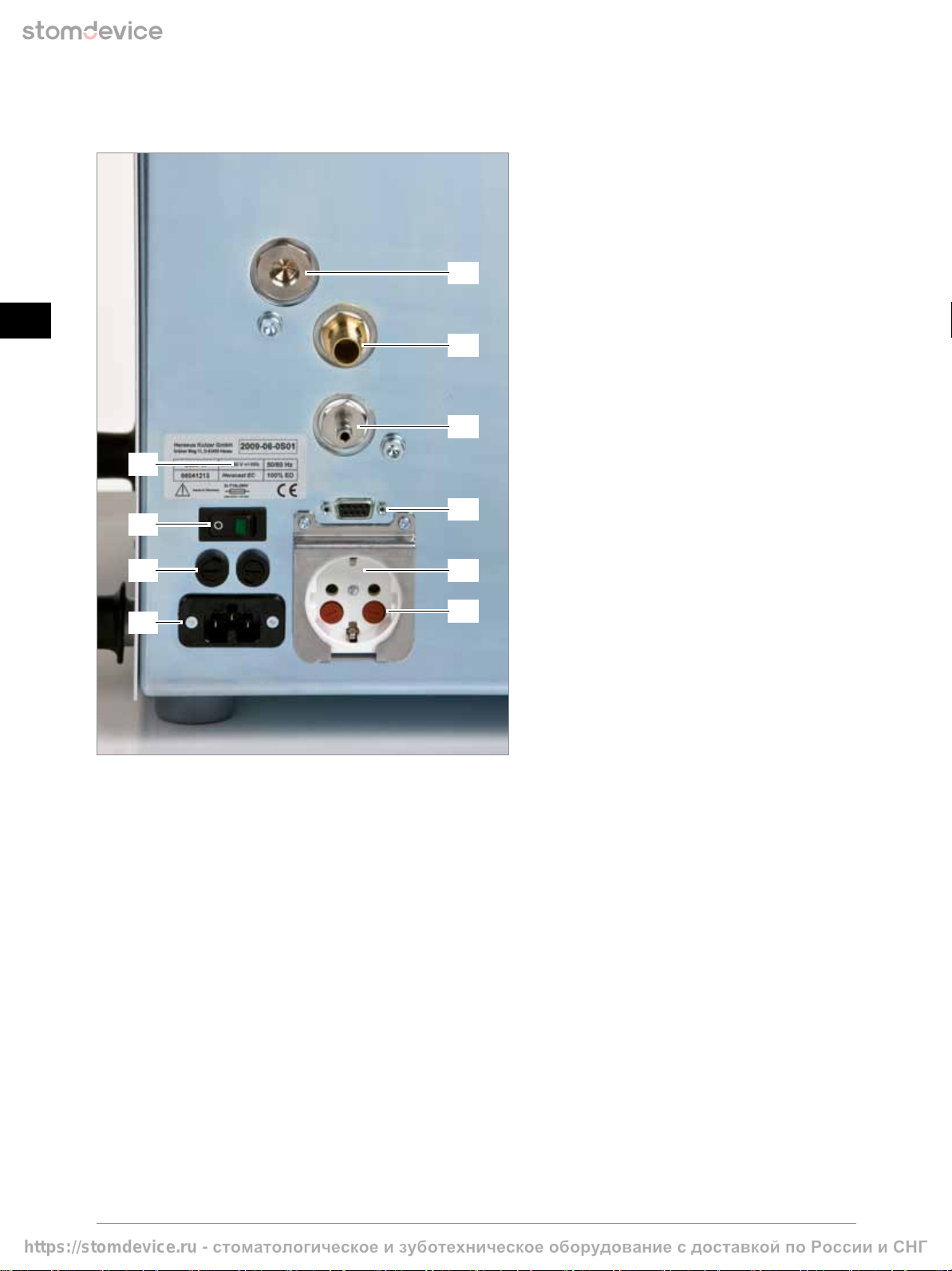
5.4 Partial view inlet and power connections
23
24
25
26 22
21
20
19
18
17
17 Compressed air prefilter for pilot valves (for service only)
18 Compressed air supply
19 Vacuum connection
20 Interface RS232 (for service only)
21 Mains connection for vacuum pump
22 Fuses for vacuum pump (T 6.3A)
23 Type plate
24 Power switch
25 Unit fuse (T 16A)
26 Mains connection
6 Location and installation
6.1 Transport
Carefully transport the unit horizontally to prevent the pump oil from leaking and damaging the unit. Packings and units must
not be stacked. Shocks must be avoided! If there is a risk of frost during the transportation of the unit, the cooling water must be
removed from the unit. Please notify the service technicians.
For dimensions and weight refer to paragraph 12 Technical data.
6.2 Unpacking
Remove straps. If required, screw in the carrying handles at the corners of the unit.
https://stomdevice.ru - стоматологическое изуботехническое оборудование сдоставкой по России иСНГ
Operating instructions
Heracast EC
- 13 -
GB
DE
GB
FR
ES
IT
PT
NL
SE
DK
NO
FI
GR
6.3 Set-up
Location: Table with load bearing capacity of at least 70 kg.
Table area (w x d): 650 x 550 mm.
The casting machine must be placed on a solid, skid-proof surface (laboratory desks, racks) so that a horizontal safe position
is ensured. The room temperature should not be more than 40 °C.
Air inlet and outlet openings in the housing of the unit (rear and lower surface) must not be covered or blocked.
Minimum distance to the wall: 100 mm.
CAUTION
Following instructions must be strictly followed:
The rear side of the unit must be at least 100 mm away from the wall to avoid blocking the air outlet
of the built-in fan.
There must be no combustible materials, e.g. newspapers and similar, present near the casting machine and
in particular near the casting chamber and under the unit.
To transport the unit do not lift the unit at the chamber! Risk of damaging the unit!
Risk of damage and injury in case of non-compliance!
NOTE
This unit may emit high-frequency energy and cause interference with radio communication.
Should this unit cause interference with radio or television reception, it is recommended for users to eliminate
interference with one or several of the following measures:
Adjusting or changing the position of the antenna(s).
Enlarging the distance to the receiver.
Connecting the unit to a circuit separated from the circuit of the receiver.
6.4 Mains connection
Mains: 200 – 230 V (AC), 1 P / N / PE, 50 / 60 Hz, connect to mains in accordance with VDE specifications and
local power supply specifications with flexible mains connecting cable with hot appliance plug and safety
plug to a correctly installed socket with safety contacts (protection class 1).
Mains fuse: Separate safety fuse 16 A inert or safety cut-out fuse C 16 A.
Mains connection: The unit should not be connected via a connection fault current circuit breaker.
If the use of a fault current circuit breaker is specified by the local electricity board,
type 30 mA should be used.
6.5 Compressed air supply
NOTE
The compressed air must be clean and dry!
Air pressure min. 4 bar, max. 7 bar! Higher air pressure (even short-term) can result in damage to the inner
valves! To avoid this, an optional pressure reducer filter combination must be used. Order No. 66005499.
In case of moist compressed air, this pressure reducer/ filter combination or water separator / filter must also
be connected in series. The pressure reducer includes accessories for unit mounting or wall mounting.
Line cross-section (inner) min. 10 mm.
Rapid pressurization (< 1.5 sec.) is essential for the mould filling behaviour. Non-compliance can result in faulty
castings. The use of a separate compressed air tank (< 10 mm) in the direct vicinity of the casting machine is
recommended for small line cross-sections. Order No. 66008921.
NOTE
Any guarantee claims shall be excluded in case of malfunctions or damage resulting from inadequate
compressed air supply!
https://stomdevice.ru - стоматологическое изуботехническое оборудование сдоставкой по России иСНГ

- 14 -
GB
DE
GB
FR
ES
IT
PT
NL
SE
DK
NO
FI
GR
6.6 Vacuum air connection
CAUTION
Prior to operating, check whether the nominal voltage corresponds to the value indicated on the type plate
of the vacuum pump.
Attach the hose of the vacuum pump to the connection of the casting machine. Connect vacuum pump to the socket
(rear of the unit). The power cord must not touch the casting chamber. (Follow to the working instructions of the vacuum pump!).
6.7 Filling the cooling system
For safety reasons the inner cooling system is only prefilled with a small quantity of antifreeze and anticorrosion agent.
To fill the system completely, open the side trap door and fill the container with tap water (do not use distilled water).
If the water level has reached the value “MAX.”, stop filling.
CAUTION
Do not fill over the “MAX.” marking. Risk of damaging!
After initial operation, the cooling water level must be checked again and the unit must be filled up with
pure tap water.
WARNING
Risk of electric shock when unit is opened. Unplug the unit, before opening the side flap.
6.8 Room ventilation
The room in which the unit is operated must have sufficient technical ventilation. The unit must not be operated in
recesses that cannot be ventilated. If several units are to be placed in one room, special ventilation measures may be required
(e.g. zone ventilation).
7 Operations
The following pages are to provide basic information and hints which are essential for successful and error-free working.
Please observe the order of the working steps.
Mostly, casting errors cannot be attributed to the casting machine.
7.1 Putting into operation
When the machine is switched on the request “Please open and close the chamber” appears as animated icon after welcome
display.
If the chamber was closed it must be opened and then closed again.
The safety test cycle starts after correctly switching of door limit switches.
Welcome Safety test Main menu
The vacuum pump evacuates the chamber. Then the induction coil and the casting ring are turned automatically and
pressurization is started. Prior to turning back the induction coil and the casting ring to the basic position the chamber
is deaerated automatically.
In case of a defect or an error, a respective message is displayed.
Once the test run has been successfully completed, the machine is ready for operation.
CAUTION
If an error cannot be eliminated, please contact the responsible service agent.
The addresses can be found on the paragraph 15 Service of these instructions.
Unauthorized opening of the machine include unknown risks and are not permissible.
https://stomdevice.ru - стоматологическое изуботехническое оборудование сдоставкой по России иСНГ
Operating instructions
Heracast EC
- 15 -
GB
DE
GB
FR
ES
IT
PT
NL
SE
DK
NO
FI
GR
7.2 Putting out of operation
Remove crucible and casting ring from the chamber.
Let the unit cool down for approx. 3 minutes before switching it off.
Switch off the unit; unplug the unit if it is not to be operated for longer periods.
Remove contamination from the crucible, fielding plate and the chamber.
7.3 Errors and causes
If a malfunction occurs during test run or when operating the unit, the malfunction is shown on the display.
There are various warnings (W) and error messages (E).
Warnings are indicated on the display by an “ATTENTION“ icon (see paragraph 8.1.1 Icons in the status display); the process
is continued. If an error occurs, the process is terminated immediately and the error screen of the information menu is activated.
The current error is inverted (see paragraph 8.5 Error history).
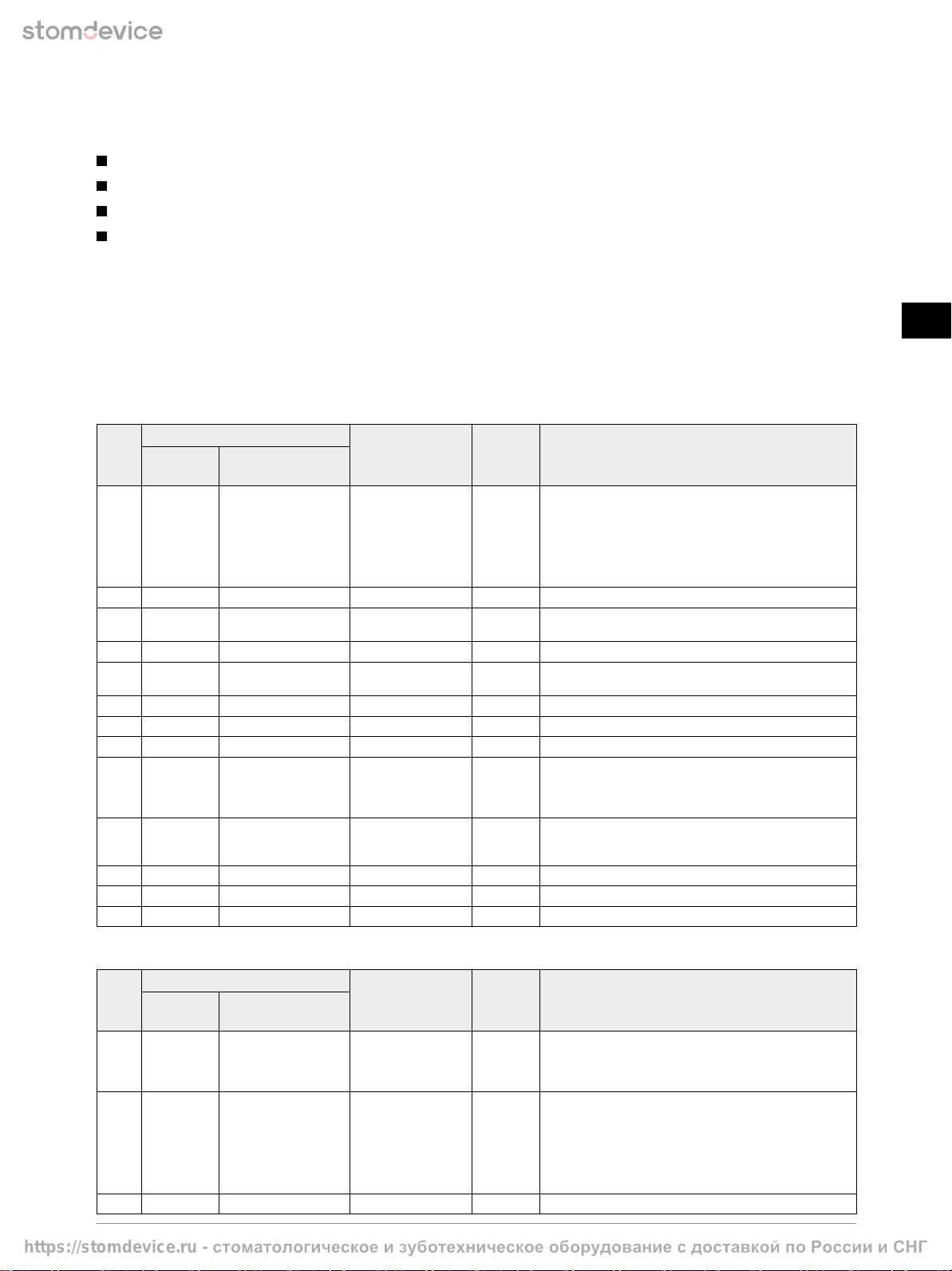
The following warning messages may be displayed:
Code Message Condition Time
delay
Possible cause
Assembly
Group
Component
W2 Cooling Waterflow too low < 800 ml 4 sec. •
Blocked drains at:
– Cooler
– Oscillator
•
Defect at:
– Water tube
– Water pump
– Flow meter
W3 PWR Supply PWR-Temp. > 75°C > 75 °C 1 sec. •
Switching power supply too warm
WC Cooling OSC-Temp. > 65 °C > 65 °C 1 sec. •
Oscillator temperature (outlet) too high.
Allow to cool down
WD Cooling OSC-Temp. < 10 °C < 10 °C 1 sec. •
Oscillator temperature (outlet) too low
WE Cooling WTR-Temp. > 55 °C > 55 °C 1 sec. •
Cooling liquid-temperature (inlet) too high.
Allow to cool down
WF Cooling WTR-Temp. < 10 °C < 10 °C 1 sec. •
Cooling liquid-temperature (inlet) too low
WG Cooling AIR-Temp. > 50 °C > 50 °C 1 sec. •
Inside temperature too high
WH Cooling AIR-Temp. < 10 °C < 10 °C 1 sec. •
Inside temperature too low
WL Induction Check crucible Deviation of
SET / ACTUAL power
in the graphite
crucible > 5 %
4 sec. •
Graphite crucible:
If weight < 7g, replace graphite crucible
•
Defect at:
– Inductor
WM Vacuum Vac. not reached > 500 mbar. 15 sec. •
Check pressure air supply
•
Check vacuum pump
•
Check chamber sealing for air leakage
WO Pressure Pressure too low < 2.9 bar 4 sec. •
Check pressure air supply
WP Pressure build-up time > 2 sec. > 2 sec. 4 sec. •
Pressure build-up too slow. Check compressed air supply
WR Pressure Pressure too high > 3.5 bar 4 sec. •
The warning may occur, if large casting moulds are used
The following error messages may be displayed:
Code Message Condition Time
delay
Possible cause
Assembly
Group
Component
E1 VAC-Sensor check pressure sensor If ambient pressure
of < 600 or
> 1200 mbar
measured
2 sec. •
Check pressure sensor
•
Cable break
E2 Cooling Waterflow too low < 600 ml 4 sec. •
Blocked drains at:
– Cooler
– Oscillator
•
Defect at:
– Water tube
– Water pump
– Flow meter
E3 PWR Supply PWR-Temp. > 100 °C > 100 °C 1 sec. •
Switching power supply too hot
https://stomdevice.ru - стоматологическое изуботехническое оборудование сдоставкой по России иСНГ
- 16 -
GB
DE
GB
FR
ES
IT
PT
NL
SE
DK
NO
FI
GR
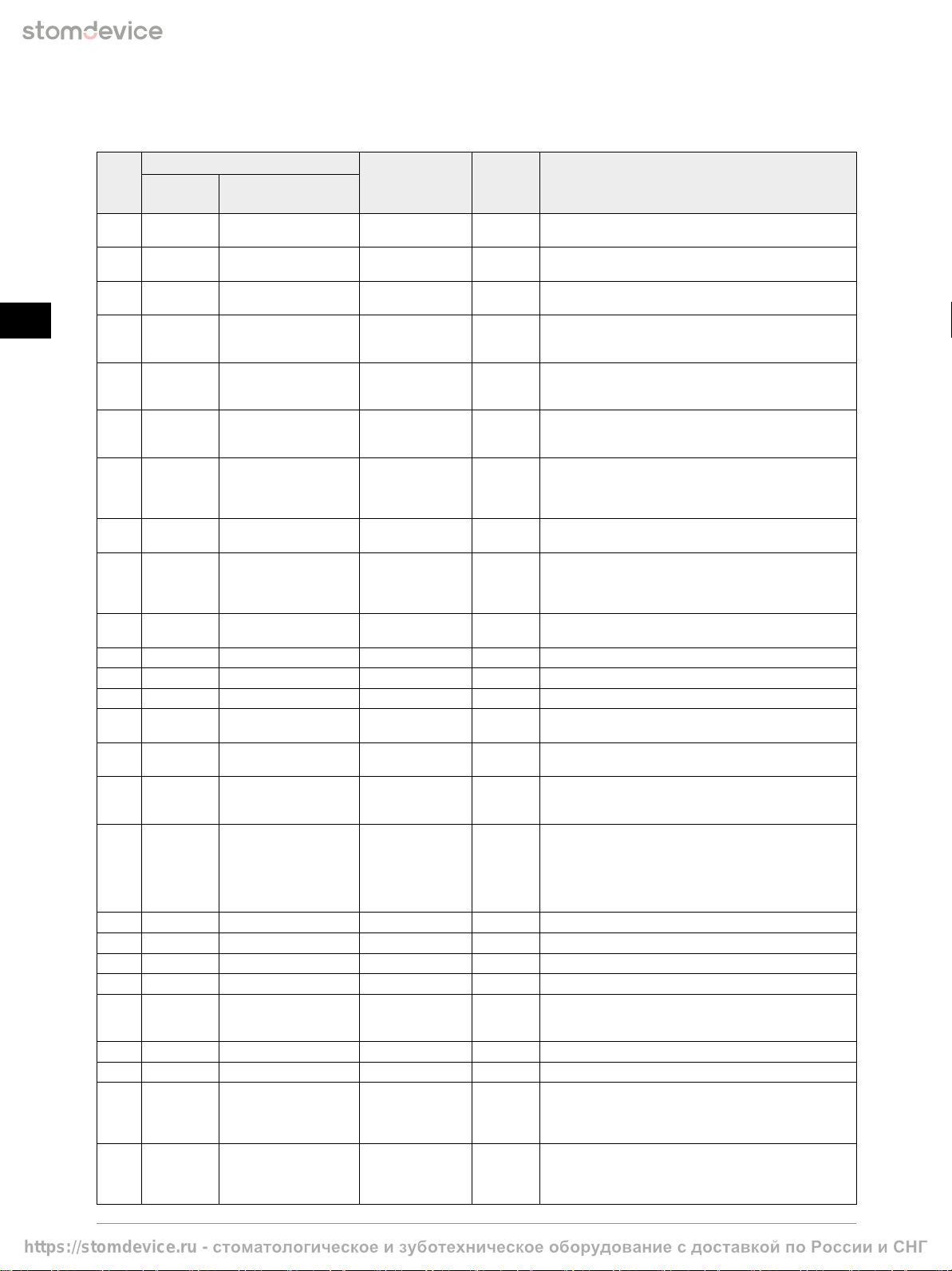
The following error messages may be displayed:
Code Message Condition Time
delay
Possible cause
Assembly
Group
Component
E4 TMP-Sensor WTR-Temp.-Sensor Short circuit or
broken wire
2 sec. •
NTC sensor defect (inlet)
E5 TMP-Sensor OSC-Temp.-Sensor Short circuit or
broken wire
2 sec. •
NTC sensor defect (outlet)
E6 TMP-Sensor AIR-Temp.-Sensor Short circuit or
broken wire
2 sec. •
Sensor defect
E7 Switches Chamber position NO / NC contact
not antivalent
1 sec. •
Check limit switch for chamber position;
readjust if necessary
•
Broken wire
E8 Switches Chamber lock OPEN NO / NC contact
not antivalent
1 sec. •
Check limit switch for chamber lock position “OPEN”,
if necessary readjust
•
Broken wire
E9 Switches Chamber lock CLOSED NO / NC contact
not antivalent
1 sec. •
Check limit switch for chamber lock position “CLOSED”,
if necessary readjust
•
Broken wire
EC Cooling OSC-Temp. > 70 °C > 70 °C 1 sec. •
Oscillator temperature (outlet) too high.
Allow to cool down
•
If message is still displayed after 10 min. cooling:
– Short circuit at NTC sensor (outlet)
ED Cooling OSC-Temp. < 5 °C < 5 °C 1 sec. •
Oscillator temperature (outlet) too low
•
Broken wire at NTC Sensor (outlet)
EE Cooling WTR-Temp. > 60 °C > 60 °C 1 sec. •
Cooling liquid-temperature (inlet) too high.
Allow to cool down
•
If message is still displayed after 10 min. cooling:
– Short circuit at NTC sensor (inlet)
EF Cooling WTR-Temp. < 5 °C < 5 °C 1 sec. •
Cooling liquid-temperature (inlet) too low
•
Broken wire at NTC Sensor (inlet)
EG Cooling AIR-Temp. > 60 °C > 60 °C 1 sec. •
Inside air temperature too high
EH Cooling AIR-Temp. < 5 °C < 5 °C 1 sec. •
Inside air temperature too low
EI Induction PDC > 1900 W > 1900 W 1 sec. •
Generator power output too high
EJ Induction Energy control After 300 kW/s – •
Induction automatic cut-off.
This is not an error but a protective measure!
EK PWR Supply I / O reading error –1 sec. •
Received no acknowledgement from
switching power supply
EM Vacuum Vac. not reached > 500 mbar
> 100 mbar
25 sec.
45 sec.
•
Check pressure air supply
•
Check vacuum pump
•
Check chamber sealing for air leakage
EN Leakage Vacuum / pressure
During Self test:
Pressure rise in the
vacuum > 30 mbar
or pressure drop
when pressure
> 300 mbar
4 sec. •
Check chamber sealing / valve block for air leakage
EO Pressure Pressure too low < 2.7 bar 4 sec. •
Check pressure air supply
EQ Pressure Release time > 6 sec. > 0.2 bar 6 sec. •
Check air release filter at valve block
ER Pressure Pressure too high > 3.7 bar 4 sec. •
Check valve block / pressure sensor
ES Movement Check POTI Short-circuit – •
Position sensor defective
ET Movement POTI-movement No change at UPoti 1 sec. •
Turning motor not activated:
– Check position sensor
– Check turning motor
EU Movement Basic position +/– 15 digits 3 sec. •
Basis position not reached
EV Movement Casting position +/– 15 digits 3 sec. •
Casting position is not reached
EW Locking Rotation to OPEN Limit switch for
locking “OPEN”
not achieved
3 sec. •
No rotation of motor
•
Cable breakage
•
Check limit switch for locking position “OPEN”,
adjust if required
EX Locking Rotation to LOCK Limit switch for
locking “LOCK”
not achieved
3 sec. •
No rotation of motor
•
Cable breakage
•
Check limit switch for locking position “LOCK”,
adjust if required
https://stomdevice.ru - стоматологическое изуботехническое оборудование сдоставкой по России иСНГ

Operating instructions
Heracast EC
- 17 -
GB
DE
GB
FR
ES
IT
PT
NL
SE
DK
NO
FI
GR
7.4 Manual unlocking of casting chamber
In the event of a bad casting result or excessive contamination of the casting chamber, the chamber locking mechanism may be
jammed or blocked in the worst case. Afterwards, automatic unlocking of the chamber locking mechanism is no longer possible.
Manual unlocking will support the automatic process.
Step 1. Preparation
Please switch off the device.
Remove the sealing cap (1) and insert
the steel stick included in the scope
of delivery (2) into the guide as shown
in the photos on the right).
Make sure to use a hammer and apply
gentle blows to the steel stick to
support the automatic chamber locking
mechanism.
Step 2. Manual unlocking
Please switch on the device. Press the left key while the welcome screen is displayed.
The mechanical unlock program is loaded.
Start manual unlocking by pressing the right “START” key. The vacuum pump
is automatically activated and creates a vacuum inside the chamber.
From a vacuum level of 250 mbar, an acoustic signal is heard and the speaker icon
is animated. As long as the signal is heard, you may apply gentle blows to the steel
stick to support automatic unlocking of the chamber.
As soon as the chamber is opened, the acoustic signal is stopped and the manual
unlocking process is completed. Follow the instructions shown on the display,
switch off the device and clean the casting chamber.
If the lock cannot be opened during the first cycle (8 seconds), the procedure
can be repeated as often as desired.
Please inform your responsible regional Heraeus Kulzer service partner if the
chamber locking mechanism does not unlock after repeated attempts.
NOTE
Always attempt to unlock manually without the support of the automatic
chamber unlocking mechanism.
ATTENTION
The acoustic signal can be heard for approx. 8 seconds. The automatic
chamber unlocking mechanism should only be supported during this
period. Failure to follow these instructions may lead to damage to the
locking motor.
2
1
https://stomdevice.ru - стоматологическое изуботехническое оборудование сдоставкой по России иСНГ
- 18 -
GB
DE
GB
FR
ES
IT
PT
NL
SE
DK
NO
FI
GR
8 Working with Heracast EC
After switching on and successful completion of the Auto-Test, the user is automatically directed to the main menu.
In this menu additional options are available.
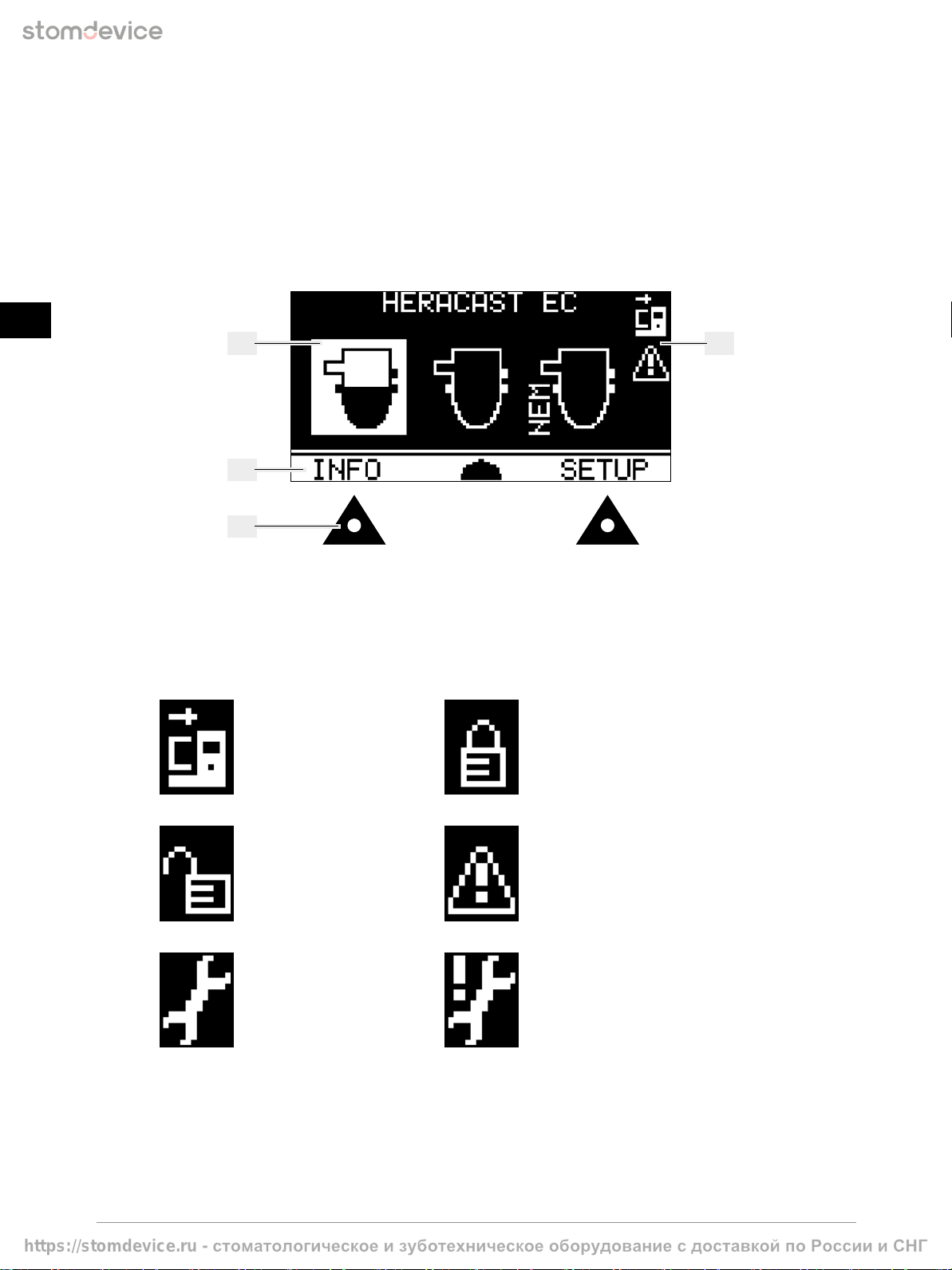
8.1 Controls for operating
The Heracast EC is operated using two buttons and a turning knob with noticeable pressure point.
The functions of the buttons vary depending on the active menu and device status.
27
28
29
30
27 Choices (display of the selected item is inverted)
28 Variable menu bar; options can be selected using the push button
29 Push button for menu bar
30 Status displays
8.1.1 Icons in the status display
Chamber open
Indicates that the casting
chamber is open.
Chamber locked
Indicates that the casting
chamber is closed and
locked.
Chamber unlocked
Indicates that the casting
chamber is closed but not
yet locked.
Message
Indicates that a warning
or error message occurred.
MAINTENANCE icon
After 3000 castings!
Please contact the
Heraeus Kulzer Service.
MAINTENANCE icon
After 10,000 castings!
Maintenance of safety-
relevant components.
Please contact the
Heraeus Kulzer Service.
https://stomdevice.ru - стоматологическое изуботехническое оборудование сдоставкой по России иСНГ
Operating instructions
Heracast EC
- 19 -
GB
DE
GB
FR
ES
IT
PT
NL
SE
DK
NO
FI
GR
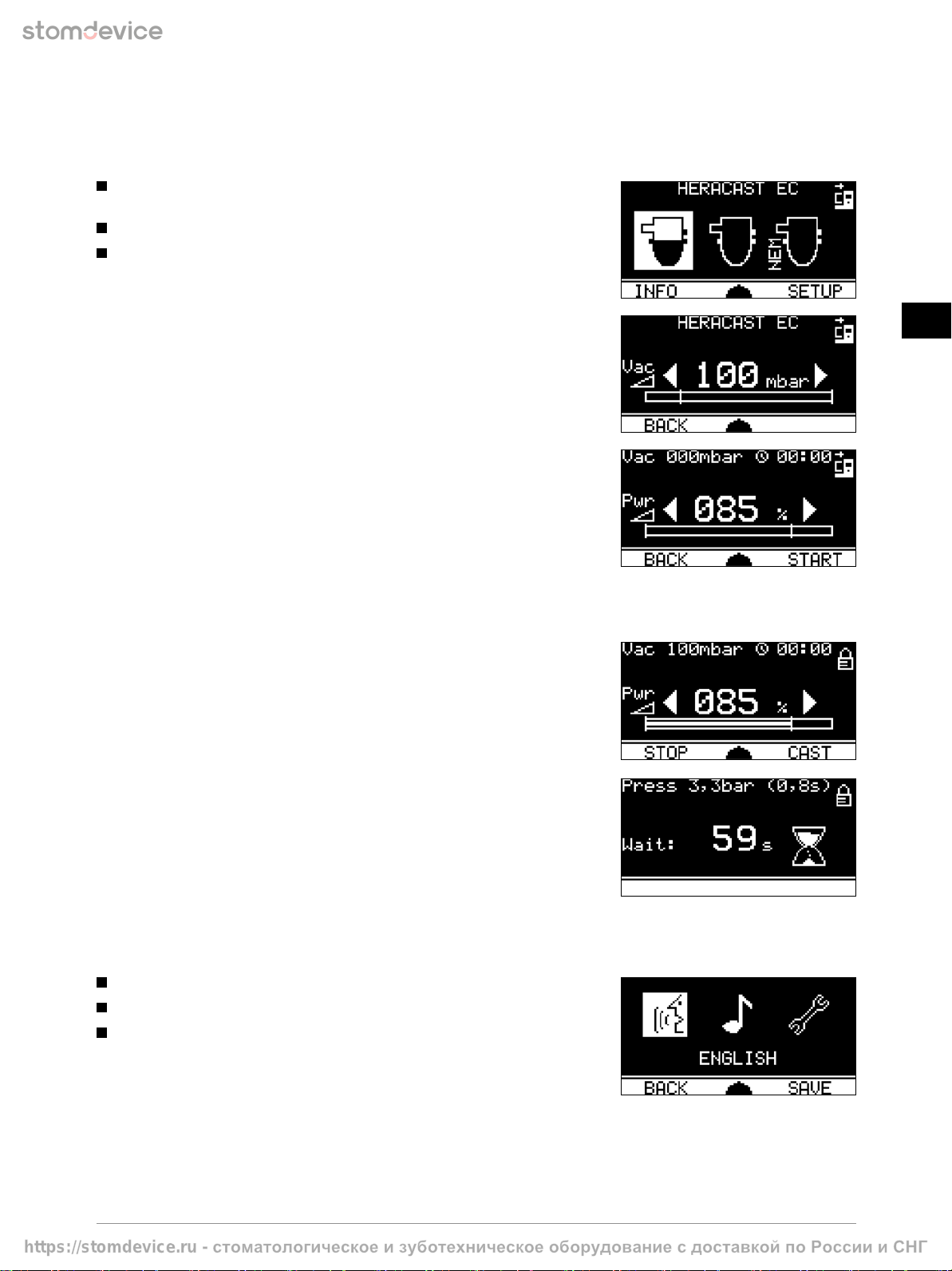
8.2 Casting Menu
The main menu includes the following options, which you can select using the turning knob:
Ceramic crucible with graphite insert (for gold casting or high-gold content
ceramic bonding alloy).
Ceramic crucible (for Pd-based alloys or gold Pd alloys).
NPM crucible (for NPM or CoCr frameworks).
Push the turning knob to confirm the selection.
In the Enter Vacuum menu you can accept the default value or specify a different
value by turning the turning knob. The currently specified vacuum value is also
indicated in the graphic vacuum indicator.
Push the “BACK” button to return to the previous menu.
Push the turning knob to confirm the specified vacuum value.
The Casting menu displays the entire casting process. In the upper left corner the
current vacuum value [mbar] or pressure value [bar] is displayed with the pressuriza-
tion time in seconds; a timer [mm:ss] is displayed on the right. The timer starts
automatically with induction and can be reset to 00:00 by pressing the turning knob.
In the lower part of the Casting menu the currently specified power value is displayed
as percentage in large numbers. You can change the default value anytime by turning
the turning knob to the left or to the right.
Now close the chamber and start the melting process by pushing the key under the “START” menu item.
The chamber will automatically be locked and the specified target vacuum will be built up. Induction starts automatically
from a vacuum value of 450 mbar upwards.
Any power adjustments during melting must always be performed manually.
Push the “STOP” key when premelt is completed.
Push the “CAST” key to pivot the inductor coil and the casting ring immediately.
Due to its own weight the melt will flow into the cavities of the casting mould.
Simultaneously, compressed air is admitted to the chamber automatically (audible
pressure surge) and the melt is pressed into the finest areas of the casting mould.
After the alloy has solidified (approx. 60 seconds after pivoting), the inductor coil
and the casting ring pivots back automatically and the chamber unlocks. The casting
process is completed. Open the chamber and carefully take out the casting ring.
8.3 Setup Menu
The Setup menu includes the following options, which you can select using the turning knob:
Language (German / English / Japanese).
Acoustic signals (ON / OFF).
Service.
Changed settings must always be saved using the “SAVE” key.
Unsaved changes will not be applied.
To exit the Service menu push the “BACK” key.
https://stomdevice.ru - стоматологическое изуботехническое оборудование сдоставкой по России иСНГ

- 20 -
GB
DE
GB
FR
ES
IT
PT
NL
SE
DK
NO
FI
GR
8.4 Info Menu
The following information can be viewed in the Info menu:
Device serial number (S/ N).
Process counter.
Total operating hours.
Software (SW) and hardware (HW) version.
Push the “ERROR” to open the error history.
To exit the Info menu push the “BACK” key.
8.5 Error History
In the error history you can browse through the most recent warning and error messages by turning the turning knob.
The message currently selected is inverted and contains two lines.
These messages are displayed as follows:
1. Line: Process counter and (Error code assembly group)
W = Warning message, E= Error message
2. Line: Detailed message description
Inactive messages contain a single line only.
Line: Process counter and (Error code assembly group)
Push the “TOP” key to jump to the latest message.
To exit the error-history push the “BACK” key.
9 Melting and casting
The technical procedure is described in the following.
For alloy-specific application information, see paragraph 10 Alloys.
9.1 General
NOTE
Please request information brochures on casting according to the Heraeus system.
9.2 Suitable investment materials
NOTE
No graphite-containing investment materials must be used. The graphite content can result in degassing
or in damage to the alloy. We recommend to use our graphite-free, phosphate-bonded investment materials.
9.3 Premelting
In order to obtain uniform casting conditions, all alloys are premelted.
The mould is placed into the casting chamber after premelting the alloy.
Exception: Titanium- and aluminium-containing alloys, see paragraph 10.4 Titanium and aluminium containing alloys.
CAUTION
The alloys must be observed continuously during premelting. Generally, each melt may only be observed through
the blue glass because of the high luminous intensity. Risk of getting blinded! The premelting process may only
be interrupted when all the alloy has melted! The alloy has a spherical shape; there are no protruding edges of the
molten material. Splitting up of the oxide layer is without any relevance during melting in the graphite crucible.
When melting large quantities (more than 50 g), small individual portions must be premelted. The metal should only
be melted so that filling in of the next portion is possible. Only in the last premelt all the alloy is melted.
Exception: CoCr partial denture alloys (see paragraph 10.3 CoCr partial denture and non-precious metal alloys).
Titanium- or aluminium-containing alloys (see paragraph 10.4 Titanium and aluminium-containing alloys).
NOTE
We recommend to do the premelt with 100 % power.
https://stomdevice.ru - стоматологическое изуботехническое оборудование сдоставкой по России иСНГ
This manual suits for next models
1
Table of contents
Other Heraeus Medical Equipment manuals


