Spectrum DSP M2 User manual

Spectrum DSP M2 User Manual V1.1
►Spectrum DSP M2 User Manual◄
C. Turner, KA7OEI ▲ R. Colclough GW8RDI
September 0 3
DRAFT FIRST RELEASE
P 1
Copyright (additions and logos) 2022-2023 QuantumSDR™ Group
All rights r s rv d

Spectrum DSP M2 User Manual V1.1
Intro uction:
The Quantum SDR project was formed to develop an affordable wide-band spectrum scope with waterfall that
can be easily connected to any radio receiver or transceiver, incorporating the latest SDR technologies, including
machine learning and artificial intelligence, dramatically improving access to the Spectrum for any radio system.
The team's aim is to continue enhancing the Spectrum software, and to develop a variety of new models,
following the feedback we receive from users. You can contact us at [email protected] or through our
Facebook group, QuantumSDR.
Thank you for your support.
The Spectrum DSP M incorporates the GUI (graphics user interface) originally developed by the Universal
HAM SDR (Software Defined Radio) project and extended by Quantum SDR. It is reproduced here with their
permission and our thanks.
Configuration: Touch interface an Transceiver/Receiver association
The Spectrum DSP arrives configured for the transceiver requested during ordering. There are two items that
you may want to configure, one is the touch interface so that so that clicks and swipes align with the on-screen
areas and buttons.
To realign the touch screen interface, reboot the Spectrum, and immediately that a small blue square shows,
press the stylus on the screen and keep pressed. The TOUCH LINE TO RESET SETTINGS message should be
displayed, move the stylus through that line. The touch calibration procedure should then start, else reboot and
try again. Follow the on-screen instructions, finalizing by drawing through the green square, or if you want to
repeat the calibration, through the red square.
If you press too soon after booting, the unit will perform a FACTORY RESET, following which you can reboot and
calibrate the touch screen if needed.
Once set-up, click MENU and make a long-press on EXIT/* to save the new settings.
The other setting is to associate the transceiver or radio with which the Spectrum must connect via the CAT
connection. This can be set by clicking the MENU button, then when the menu is displayed, make a short down-
swipe in the middle-right of the LCD until Configuration Menu is reached, then another down-swipe on the right-
side of the screen to open that menu. You can then select the associated transceiver and Spectrum mode, such
as BiSync, slave or master.
NOTE YouTube instruction video
The LCD requires a light yet firm touch. Long-presses are activate when the stylus stays in contact over 0.6
seconds.
There is a video in our YouTube page where you can see how this is performed:
https://youtu.be/A_YlSJJQLGM?si=aTvMzkuZGbk8A-Cz
What radios can the Spectrum be used with?
The Spectrum DSP can connect to any radio system that has either an IQ port, IQ point on it's PCB (such as the
Electaft KX , uSDX (tr)usdx and newer QRP Labs radios), or a connection to the IF stage output (model M3 or
higher).
If you need support connecting your radio, please contact us.
P 2

Spectrum DSP M2 User Manual V1.1
Typical installations
Concept – Xiegu G90 to wide DSP
The Xiegu G90 is an excellent and
feature-packed HF transceiver that's
key limitation is it's small display. By
the addition of the Spectrum DSP that
small display is converted into the
Zoom window, showing a close up of
the stations nearest to tune frequency.
Perfectly synchronized via the CAT
connection, the Spectrum DSP
becomes part of the station to provide
not only a wide-band spectrum window
that's zoomable from 3 to 19 Khz, but
also an independent 19 Khz tuning
window, where with the drag of the
stylus, you can instantly listen to
stations without having to spin the dial.
When you find the station you want,
one click is all it takes to synchronize
the G90. DSP noise & notch filtering are
also provided.
This combination results in a better
option that upgrading to many of the
newer DSP transceivers with larger
screens that often lack items such as
the ATU and full 0W output.
Concept – Elecraft KX3 and KX to wide DSP
The classic Elecraft KX and KX3, with it's beautiful smooth turning dial, synchronizes
perfectly to the Spectrum DSP, providing an independent 19 Khz of instant tuning across the
band with the stylus or a light touch on the screen. When you find the station that you want,
one click synchronizes the Elecraft ready for operation. The Spectrum allows you to view the
whole band, zooming from 3 right out to 19 KHz, and providing bidirectional tuning
synchronization for the fastest access to stations across the bands.
P 3

Spectrum DSP M2 User Manual V1.1
Concept – Classic to wide DSP
The Spectrum DSP can also connect to the IF signal of any classic radio, allowing those
beautiful sets to be used with the very latest features like any modern transceiver.
The connection to the IF of most receivers requires a simple miniature coax cable connection
direct to the IQ input on the Spectrum. Connection notes are available for several models of
radios.
If you require any help connecting your radio, please get in contact.
P 4

Spectrum DSP M2 User Manual V1.1
Graphical user-interface (GUI):
Note: All references to TX operation are inclu e for the future inclusion of a TXRX mo ule which
converts the Spectrum into a DSP transceiver.
The touch screen is easily controlled once the basic technique is mastered.
Clicks with the stylus should be made in a deliberate manner, approximately half a second
long will activate the menu and control buttons, any longer and they will be detected as a
long-press, which activates secondary functions which most buttons and touch areas posses.
You can practice this by clicking on the MENU button. A short but deliberate press will display
the menu list, a long-press will mute the audio, making another long-press will reactivate the
audio. If the volume is too low, click DSP/OFF and stroke up on the left-side.
A video on YouTube is available showing how to use the touch interface, available here,
https://youtu.be/A_YlSJJQLGM?si=0QFNF63dCD417fZ8
GUI controls are software defined, but for the purpose of simplicity they are typically defined
as follows:
•Power on/off – Tapping the LCD screen several
times wakes the unit from power-save mode. To
power-off, press Menu then click PWR and
immediately Confirm.
•Ban change – To change band click the highest part
of the frequency display, which will then display the
band keypad. You can also change band by clicking
the red or green lines to the right-side of the frequency display.
•Display Mo e – The display modes are toggled by clicking on the top of the Spectrum
display area. If they gray header bar is shown, click on the left of the bar to toggle
through the modes.
P 5
Important: SDR Offset
For best receive quality the
frequency offset mode should
be activated with a long-press
on the TUNE/O button. When
this button is green, the offset
is activate.
Figure 2: Main touch display of the Spectrum DSP

Spectrum DSP M2 User Manual V1.1
•Tuning – The Spectrum must be in Master, BiSync or Slip-Tune modes to enable
tuning, else tuning is controlled from the attached transceiver when connect via CAT.
Click MENU then select Configuration Menu to change mode.
Tuning can be accomplished by clicking anywhere on the Spectrum band. To fine tune
touch the centre of the spectrum display keeping the stylus down and drag left or right.
Enabling SNAP/Bl with a single click will increase the speed of frequency change
through dragging. Fine tuning can be made with the two buttons << >> a single press
shifts the frequency 1KHz, a continuous press will continually bump the frequency by
100Hz. You can also click the right-most digits of the main frequency display to
alternate between a 0 hertz offset, and 500 hertz, common channel steppings.
•Slip-tune – Click the SLIP/SP button once to enter and leave slip-tune mode. When
activated the text will show green. When activated you can independently tuning by
dragging the blue tune bar across the spectrum. The transceiver does not change
frequency and the audio from the Spectrum will be heard and the frequency shown.
Click SLIP/SP again will then synchronize the transceiver to the Spectrum frequency.
A video on YouTube here explains the procedure: https://youtu.be/8nApkXsXI7A?
si=YmrLRjyOvIi7Z6jf
A vi eo on YouTube shows how to use the Slip-tune mode here.
Slip-tune allows complete tuning free om over 19 Khz without re-tuning the TX/RX
•Dial-tune – Click the TUNE/O button bottom-right to display the virtual dial. Tune by
drawing a circle with the stylus CW or CCW. To tune faster, make a long-press on the
buttom button marked VFO A (or B), when this is shown red fast tuning mode is
activated. The tuning is very accurate, and makes it easy to fine tune.
P 6

Spectrum DSP M2 User Manual V1.1
Figure 3: Virtual dial: The Spectrum after clicking the TUNE/O button.
•Volume – Click the DSP button centre-left then stroke up and down on the left-side of
the LCD screen.
•AFG – Click the DSP button centre-left then stroke up and down in the middle of the
display to adjust. Click the AGC box to change to BAS, TRB (treble) or AGC speed
(SLO etc), then stroke up and down in the middle of the LCD to adjust.
•RIT – Click the DSP button centre-left then stroke up and down on the right-side of the
screen to adjust RIT (Receiver Incremental Tuning), note that its function may be
changed by clicking the RIT box to adjust the sending speed (in Words Per Minute) in
the CW mode, or to adjust the Microphone or Line-In gain in voice mode, etc.
•Mo e – Click the mode box in the center of the LCD to select the operating mode of
the transceiver (CW, USB, LSB, etc.) Clicking this button cycles through the available
modes. Click the button above to select digital modes, such as BPSDK and RTTY.
When “LSB/USB Auto Select” is enabled in the Standard Menu (click MENU to
access), the sideband that is not appropriate for the frequency of operation (e.g. USB
will not be selected below 10 MHz). When menu item “LSB/USB Auto Select” is
enabled, in order to change to AM you must select a mode other than LSB (or USB) –
such as CW – and then press-and-hold the Mode box - AM will then be selected.
•DSP – This button is used to control the DSP audio filter mode. When the DSP keypa
is displayed, pressing-and-holding will turn DSP on/off while preserving the current
settings. A long-click on the DSP mode will also disable it until long-pressed again.
•Filter button – (Middle-left) This button is used to select the audio passband filter of
the receiver. The button cycles through the filter that have been pre-selected in the
Filter Selection menu. The button is disabled when FM mode is selected, but
pressing-and-holding it while transmitting on FM will cause a tone burst to be
generated, if this feature is enabled. Pressing-and-holding this button will force the
selection of bandwidth that are otherwise disabled.
The row of virtual buttons at the bottom of the LCD screen are “soft” buttons, the functions of
which change depending on mode, as indicated on the LCD, and will be discussed in more
detail later in this document.
P 7

Spectrum DSP M2 User Manual V1.1
Main LCD Touch isplay
On the main display, just above the Spectrum Scope, there are a number of indicators:
•Main Frequency Display: This may be displayed either as a single frequency
(transmit/receive as in Figure 4) or as a “Split display showing both frequencies with
separate transmit and receive frequencies. If the numbers in this display are grey the
“Frequency Lock” (configured in the menu) is active. If this display is yellow, a
transverter offset has been configured.
•RIT+Tuning Display: Above and to the right of the main frequency display is a smaller
display that is offset from the main display if the RIT is set to something other than
zero.
•Ban Display: To the right of the main frequency display is an indicator of the
amateur band in which the current frequency is tuned with click areas underlined in red
and green to increment or decrement the band. If the current frequency is outside an
amateur band it will display “Gen” (e.g. “General Coverage”), depending on
configuration settings.
•Mo e In icator: Above the MHz digits of the main frequency display is the current
demodulation mode displayed on a blue background.
•Zones: These three zones are controlled via clicking the top box to toggle through the
P 8
Figure 4: The main screen (annotated) with the SPLIT function disactivated.
Wh n “Fr qu ncy Translat ” mod is on, th c nt r fr qu ncy indicator will b
shift d right of c nt r by 12 kHz to r duc th SDR nois l v l n ar DC z ro.

Spectrum DSP M2 User Manual V1.1
controls for each zone, and then swiping up and down in the three LCD screen
regions, left-side, middle, right-side. Click the DSP button to enable access, and then
swipe in the regions outside of the DSP virtual keypad that is displayed.
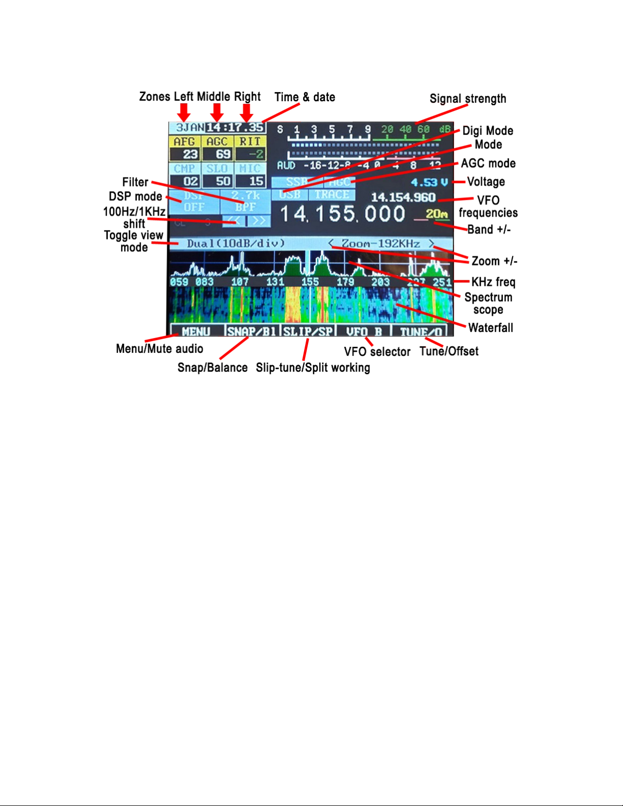
Along the top there are a number of additional indicators:
•Time & Date: This can be set by clicking MENU, then opening the configuration menu.
Please refer to the instructions on page 5, and the linked instruction video.
•S-Meter: This S-meter is nominally calibrated so that S-9 equals 50 microvolts into a
50 ohm load with each S-unit representing 6 dB. Practically speaking, the usable
range of the S-meter ranges from about S-3 to something a bit higher than “40 over”
which, if you were “run the numbers” about matches the dynamic range of the receiver!
The bottom half of the S-Meter's graticule (“S0-S9”) is normally white in color, but if the
receiver's A/D converter experiences an overload condition, it will turn red. On bands
with strong signals it is normal for this to momentarily flash red as the internal gain
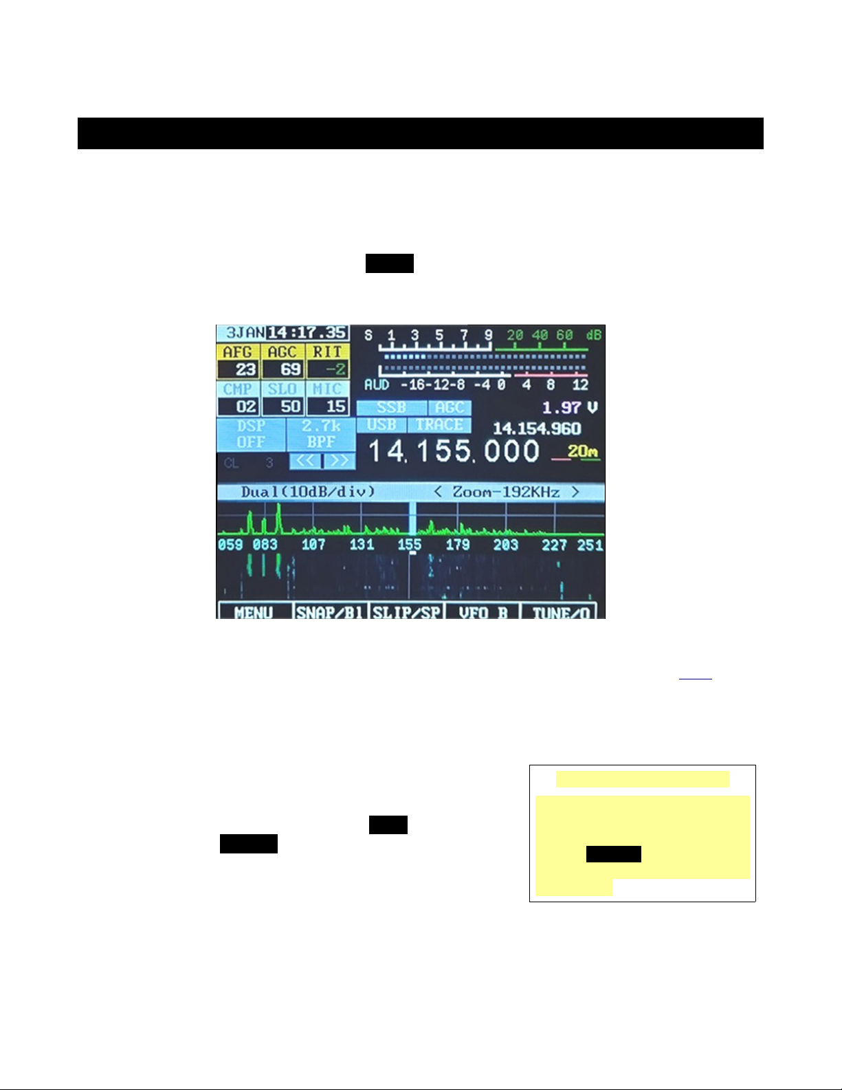
control adjusts itself. In Figures 2 an 3 the S-meter is displaying a signal level of S-
9.
•PO: The S-Meter scale, when in transmit mode, also indicates the output power from
the transmitter.
•Multi-function isplay: Below the S-Meter and Power Output meter is a multi-
function meter that, by clicking, may be used to select one of three modes: SWR,
AUDIO, and ALC.
•SWR: When in transmit mode, this meter indicates the calculated VSWR. Note
that the VSWR is calculated only when the forward power exceeds 0.25 watts.
When in SSB mode, this indicator will not show any VSWR indication
unless/until there has been some RF power that exceeds the minimum power,
allowing a calculation to be made.
•AUDIO: This indicates, in dB, the relative audio level being applied to the
MIC/Line input.
•ALC: This indicates, in dB, the amount of gain reduction that the ALC is
applying while in transmit mode. 3-1 dB of indication during typical speech is
normal.
•VCC: Below the Signal meter is a voltmeter that indicates the current supply voltage.
Below 4.40 volts, the digits are displayed in red, orange below 4. 0 volts and yellow
below 4.00 volts. The receiver may function as low as 3.3 volts.
•TRACE: To the right of the Mode button. Clicking trace will enable or disable the trace
outline shown on the scope display.
•Freq. Step [<< >>]: Just below the DSP button, and slightly to the right. If clicked
once the frequency will step + or – 1KHz. A long press will keep stepping the
frequency in 100Hz increments, ideal for fine tuning. Clicking the lower 3 digits of the
main frequency display will set the frequency to 0 Khz or 0.5 Khz.
P 9

Spectrum DSP M2 User Manual V1.1
•DSP Setting: Middle far left is the indicator of the DSP mode button. The modes
available are: ”OFF”, “NR” (Noise Reduction), “NOTCH”, and “NR+NOT” (Noise
Reduction and Notch). Trace may be automatically disabled in the CPU overloads.
Spectrum isplay:
Below the frequency readout, shown in Figure 2 and Figure 3 is a spectrum display that
shows signals that are on either side of the current tuned frequency. Along the bottom of the
spectrum display is a frequency scale that shows the frequency scaling of the graticules
rounded to the nearest kHz.
This display works very much like a spectrum analyzer with the vertical scale being
represented logarithmically, the number of dB/division being selectable by the user. To further
the analogy to a spectrum analyzer, the “reference level” (the signal level at which a particular
strength is indicated) is automatically adjusted via an AGC (Automatic Gain Control) within the
spectrum scope that operates independently from the receiver's AGC that automatically
scales the strongest signal within the passband such that it is at/near the top of the scope –
this, to allow the representation of widely varying signals on different bands without the need
of user adjustment.
Waterfall isplay
Figure 4 shows an alternate
method of displaying signals
near the currently-tuned
receiver signal is the Waterfall
Display. In this mode, the
frequency is displayed along
the “X” (horizontal) axis, just as
in the case of the Spectrum
Scope but instead of the signal
strength being displayed as
height, it is displayed as relative
“brightness”. The waterfall
displayed is so-called because
it can convey the history of
recent signal in time by showing
the most recent signals at the
bottom, but when new signals
are analyzed, the older signals are displaced vertically and the newest signals are placed
along the bottom. In this way, one has a quick visual “history” of what has occurred not only
on the center frequency.
P 10
Figure 4: A typical waterfall display in "Magnify" mode showing
+/- 12 Hz (24 Hz) of a band segment. When NOT in magnify
mode the waterfall will show +/-24 Hz (48 Hz) of a band.
Figure 4: The waterfall display unzoomed showing +/- 96 kHz (192 kHz)
of a band segment. Zoom mode allows 96 to 3 Khz to be viewed.

Spectrum DSP M2 User Manual V1.1
Scope isplay
Figure 5 shows an alternate
method of displaying signals
near the currently-tuned
receiver signal. This is the
Scope Display.
By default the scope display
shows all RF levels across the
spectrum, but making a long-
press on [SNAP/Bl] the
spectrum can be balanced to
show more defined signal
peaks. This is best done either
with the antenna grounded or
disconnected, on a quite area
of the band, or fast tuning the
transceiver while balancing,
which takes a few seconds to
complete.
Displaying both Spectrum an Waterfall:
Click the header area shown in light blue on the far left-side, to the left of “Dual(19..)”. This
will cycles through the available display modes-
Options available to both the Spectrum Scope & Waterfall
Display:
An adjustable “smoothing” filter (menu item “Scope/Wfall Filter”) is available that dramatically
improves the visibility of rapidly-changing signals In the menu system, the range of the
Spectrum Scope may be set to span either +/- 96 kHz or +/- 3 kHz, with the scope's AGC
operating only on signals within the displayed span – see the menu setting “Spectrum
magnify” for more information.
Also available are “Window function” selections that operate on the input FFT data to both the
Spectrum Scope and the Waterfall Display that pre-process the spectral data to minimize
“spill-over” of adjacent FFT “bins”. What this can do is make the Spectrum Scope and
Waterfall display look “sharper” and prevent a strong signal from “leaking” over and covering a
weak one.
Connectors:
On the right-hand side of the transceiver on the UI board are four 3.5mm three-conductor
connectors. Starting from the top, these connectors are:
•Hea phones. This is the receive audio output. It will work with headphones earbuds
P 11
Figure 5: The un oomed scope display showing +/- 96 kH
(192 kH ) of a band segment. Zooming to 3KH is permitted.

Spectrum DSP M2 User Manual V1.1
or 8 ohm speakers. An amplifier is available if required. WARNING: Ensure the
volume level is set below AFG=10 before inserting earbuds or headphones
•CAT. This connector is for connecting the TTL serial port of the associated transceiver.
Elecraft/Kenwood, USDX, ICOM and Yaseu protocols are supported.
•EXT. This jack has the DIT (PA TX) and DAH signals as shown in the connection
diagram at the end of this manual. When TX is active, the data will show in red, and
the audio will be muted.
•5V DC. This is the power connector. The outer shell is negative and the inner
conductor is positive. WARNING: Never reverse connect or connect to a higher
voltage and the unit will be destroyed.
•Debug. This connects to a computer to allow firmware updating. Please contact us
for instructions.
•IQ. This is used for interfacing with the receivers IQ signal, available either through an
IQ port or tap to the circuit board, as provided by for example, the Electraft KX .
•PC. This port connects to the PC to support IQ streaming to the PC, and provide a CAT
communications bridge to the PC using the Yaseu FT-819 protocol.
RESET BUTTON:
On the rear of the unit there is a 5mm hole, where the stylus can be used to gently
activate an MCU reset.
P 12

Spectrum DSP M2 User Manual V1.1
Operational mo es an functions:
Receive mo e:
After powering up, the Spectrum DSP will revert to receive mode on the last frequency, in the
mode and using the audio bandpass filter that was in use when it was last powered down
using the POWER button.
To adjust the volume click the DSP mode button and make short swipes up and down on the
left-side of the screen. The AFG box number will change as this is done, adjusting the
volume level.
Transmit mo e:
In transmit mode most of the controls are locked, this being done to prevent the change of
frequency, filter type and mode during mid-transmission.
TUNE mo e: Virtual dial
Tune mode may be entered by pressing the button located below the TUNE/O button on the
lower screen.
Figur 6: Th virtual dial mod provid s accurat fr qu ncy control.
Draw a circle on the screen as if you were spinning a dial to tune. If you want to tune faster
you can also make a long-press on [VFO A] which will then turn red to indicate that fast tuning
mode is active. Both modes provide accurate frequency control.
Pressing the TUNE button again will exit to the scope tuning mode. Clicking anywhere on the
scope will change frequency if the Spectrum is in Master or BiSync modes and the CAT cable
is connected to the transceiver.
P 13

Spectrum DSP M2 User Manual V1.1
VFO A (or VFO B :
When not in Menu mode, the [VFO A/B] button toggles which VFO, A or B, is currently in use.
This display will change, always indicating the currently-active VFO.
If SPLIT mode is not active, the currently active VFO's frequency, filter selection and mode
are used for both receive and transmit.
SPLIT mo e:
To activate SPLIT mode make a long-press on the [SLIP/SP] button. When active the current
VFO's frequency and filter are used for receive while the “other” VFO's frequency is that used
for transmit: The transmit mode is always that of the “active” (receive) VFO. The SPLIT
mode will be discussed in more detail below.
When SPLIT mode is on, the radio uses the currently-selected VFO's mode for both receive
and transmit, the current VFO's filter and frequency for receive and the “other” VFO's
frequency for transmit. In this mode, the main frequency display is also changed, showing
both the receive and transmit frequency, separately.
To set up for SPLIT mode one might do the following: (transceiver dependent function)
•Activate the SPLIT function by long-pressing [SLIP/SP]. The display now shows two
frequencies.
•Suppose that a DX station is transmitting on 14.155 and receiving on 14.165, USB. In
that case, you would transmit on 14.165 and receive on 14.155.
•Tune to your transmit frequency of 14.165 MHz – the receive frequency of the DX
station.
•Press the VFO A/B button to move that frequency to the “other” VFO: That is now your
transmit frequency.
•Tune to your receive frequency of 14.155 – the transmit frequency of the DX station –
and also set USB mode and your desired filter bandwidth.
•You are now ready to go! - It doesn't matter which frequency is in VFO A or B.
Important Comments relate to SPLIT mo e an VFO A/B:
•The SPLIT mode works only on the same band – this to prevent the destructive
battering of the band-switch relays that might occur with crossband operation – which
would also slow down transmit/receive switching.
◦Note that it is possible for one to set the STEP to 100 kHz and using the main knob
to tune the receive frequency to another band and operate split that way, but this is
not recommended and you do this at your own risk!
•When using FM mode it is possible to use the SPLIT function for repeater operation if
one VFO contains the repeater input frequency and the other contains the repeater
output frequency. By “swapping” the VFOs one may also do a “reverse” function and
listen to signals on the repeater's input frequency.
P 14

Spectrum DSP M2 User Manual V1.1
Menu button operation:
In “normal” operation the spectrum display will be visible on the screen and the five “Function”
buttons along the bottom of the display will have the following functions:
•MENU (button F1) – This enters the menu system, allowing the configuration of the
transceiver. Pressing and holding this button will save all settings to EEPROM.
•METER (button F2) – This button selects the mode of bar graph below the S-meter
which is used to display different parameters while transmitting. Repeatedly pressing
this button selects, in turn, the display of SWR, AUD and ALC.
•SPLIT (button F3) – This button toggles “SPLIT” mode on/off. When on (“SPLIT is
yellow), the transmit and receive frequencies are separated using VFO A and B as
shown on the main frequency display.
•VFO A or VFO B (button F4) – This button toggles whether VFO A or VFO B is the
“primary” VFO. The VFO that is being displayed is ALWAYS the one being used for
receive.
•TUNE (button F5) – This button toggles the TUNE mode on/off. Pressing and holding
this button will disable transmit as indicated by this indicator being displayed in gray.
In MENU mo e:
Pressing the MENU button (e.g. button F1) will enter the main menu system by which many
parameters of the transceiver may be configured: These parameters will be discussed in
detail later. Pressing-and-holding this button will save all settings to EEPROM.
Upon entering the MENU mode several of the “soft” buttons along the bottom of the screen
will change their function:
•EXIT/S (button F1) – This exits the menu system, returning to the main display.
Pressing-and-holding this button will save all settings to EEPROM.
•PREV (button F2) – This button goes backwards one screen or six menu items.
Pressing-and-holding this button will jump to the beginning of the menu, or to the end
of the menu if already at the beginning.
•NEXT (button F3) – This button goes forwards one screen or six menu items.
Pressing-and-holding this button will jump to the end of the menu, or to the beginning
of the menu if already at the end.
•DEFLT (button F4) – This button resets the currently-selected item to its default setting.
•PWR (button F5) – shutdown, immediate press Confirm to complete.
Note: If an item has been changed in the menu system that may need to be saved to
EEPROM by long-pressing the EXIT/S button.
P 15

Spectrum DSP M2 User Manual V1.1
How to a just values an options using the touch screen:
IMPORTANT SECTION!
All settings are adjustable through 3 zones, these can be seen in the image below:
Zone 1: See the AFG column.
Zone : See the BAS column.
Zone 3: See the AFG column.
As modes are changed these 3 columns show different names and values, but the operation
stays exactly the same.
To Activate the adjustment mode, press the [DSP] button, shown above in the image as DSP
with OFF below. The DSP virtual keypad will then be displayed, as shown above.
Next we click on the top the the column that we want to change. For example, to change the
volume, AFG must be shown in the top box of the left column. If you click the AFG box, the
yellow highlight will change to the box below, allowing that variable to be adjusted.
So the left column, Zone 1, can now be adjusted by stroking up and down on the left-side of
the LCD in the re Zone 1 region. With AFG highlighted and the DSP menu displayed, short
up or down swipes in this region will change the volume level, and the AFG number will
change. When finished just click the DSP button again to clear the DSP keypad.
This applies equally to the other two columns. Clicking the top box of each column will cycle
the boxes through all the different settings, much like how a touch interface on a cell phone
operates.
For example, click the top box of column (it may show AGC on your screen) and the text
shown will cycles from AGC to SLO, BASE and TREB. Whatever has the yellow highlight can
be adjusted by swiping up or down in its Zone area shown in red, Zone in the case of
column . With a little practice it becomes easy to use, and there is a video available on
YouTube here that shows how to use the LCD interface.
P 16

Spectrum DSP M2 User Manual V1.1
Configurable options on the main touch screen:
In the upper left corner there are a number of items on the main screen that are configurable
using the buttons and/or encoders.
•AFG - “AF Gain” (Volume Control). This is used to adjust the audio level feeding the
speaker/headphone jack. Clicking the AFG box will select whether AFG or CMP are
a juste (see below) with the “un-selected” item being “grayed” out. AFG is always
enabled when in Menu mode.
•STG - “Sidetone Gain” while in CW mode. This is used to adjust the level of the
sidetone that is heard during keying while in CW mode and while in TUNE mode by
swiping up/dwn after pressing the DSP button, on the left-side of the screen. Press the
AFG box to select whether this encoder adjusts STG or AFG with the “un-selected”
item being “grayed” out. Sidetone Gain is also adjustable from the main menu. When
not in CW mode this is replaced with “CMP”.
•CMP - “TX Compression Level” while not in CW mode. This is used to adjust the
amount of audio compression when in voice mode. When in CW mode this is
replaced with “STG”.
•RFG - “RF Gain”. This control, as the setting is decreased, causes an increased
deflection in the S-Meter and a commensurate decrease in the receiver sensitivity.
This functions in exactly the same way as the “RF Gain” control on a traditional analog
receiver and is typically used to limit the receiver sensitivity on a noisy band. the AGC
box may be used to select whether this encoder adjusts RFG or NB (see below) with
the “un-selected” item being “grayed” out. This parameter may also be adjusted from
the main menu.
•DSP – This adjust the “strength” of the DSP noise reduction, when enabled.
Pressing-and-holding the AGC box will select between this parameter or “NB” (Noise
Blanker adjust) being visible. Turning the DSP on and off will also reset the DSP noise
reduction/notch engine.
•NB - “Noise Blanker”. This control adjusts the “strength” of the noise blanker, with “0”
being “disabled.” This is a “pulse” type noise blanker operating on the wideband input
prior to filtering in the DSP input. As the noise blanker strength is increased, the color
of the number changes to warn the user that the higher numbers are more likely to
cause degradation of the receive audio. the AGC box may be used to select whether
this encoder adjusts NB or RFG with the “un-selected” item being “grayed” out.
Pressing-and-holding the AGC box will select between this parameter or “DSP” being
visible.
•RIT - “Receive Incremental Tuning”. This offsets the receiver, in 0 Hz steps, to allow
the transmit frequency to be different from that of the receiver with the actual receive
frequency being shown on the “sub” frequency display above and to the right of the
main frequency display. Button M3 may be used to select whether this encoder
adjusts RIT or WPM (see below) with the “un-selected” item being “grayed” out.
P 17

Spectrum DSP M2 User Manual V1.1
•WPM - “Words Per Minute” while in CW mode. This adjusts the Morse sending rate in
“Words Per Minute” when using Iambic mode keying. Button M3 may be used to
select whether this encoder adjusts WPM or RIT (see below) with the “un-selected”
item being “grayed” out. The Morse WPM setting may is also adjustable from the main
menu. When not in CW mode this is replaced with “MIC” or “LIN”.
•MIC or LIN - “Microphone Gain” or “Line Input Gain” when not in CW mode. This
adjusts the Microphone (or Line Input) gain, depending on which is enabled. When in
CW mode this is replaced with “WPM”. Pressing-and-holding button M3 will select
Microphone or Line-Input modes. Note that if this is changed during transmitting,
one must briefly unkey for the change of inputs to take effect.
Automatic switching of on-screen items when going from receive to
transmit:
Using the item in the “Configuration Menu” labeled “O/S Menu SW on TX” and setting it to
ON several of the on-screen items will change automatically when going from receive to
transmit and back again when returning to receive when in SSB mode: This function is
NOT available in CW mode. These parameters include:
•CMP (in voice mode)
•MIC or LIN (in voice mode)
This automatic switching facilitates the adjustment of the relevant parameters when in
transmit mode without having to pause and press the M1 and/or M3 buttons to switch the
functions of the relevant knobs.
Note that if you already had selected an alternate function while in receive (e.g. “CMP ) it will
“remember” and return to that setting after you have been in transmit and again turned to
receive.
Setting the parameter “ O/S Menu SW on TX” to OFF prevents the above parameters from
changing when going between receive and transmit.
DSP (Digital Signal Processing) Noise Re uction an Automatic Notch
Filter:
the AGC box is used to enable/disable the DSP function, providing the following settings:
•OFF – DSP Functions are turned off
•NR – Noise Reduction only
•NOTCH – Automatic Notch Filter only
•NR+NOT – Noise Reduction and Notch Filter
P 18

Spectrum DSP M2 User Manual V1.1
Pressing-and-holding the AGC box will “save” the currently-selected DSP mode, if on, and
turn it off. Pressing-and-holding this button again will restore the mode(s) that had been
configured when it had been turned off.
The “strength” of this filter may be adjusted using the menu item #10, “DSP NR Strength” -
but be very careful with this as it easy to go overboard with this setting. If it is set too high,
the artifacts caused by the noise reduction (e.g. “hollow or “watery sound) can be worse
than the interference than you are trying to remove!
The “strength” may also be set using the AGC box and swipping up/dwn in the middle-right
area without having to enter the menu system. To do this:
•Enable DSP “NR” mode by pressing the DSP button and pressing the NR button.
•Press the AGC box so that the highlighting changes from RFG to DSP on the screen.
•If “NB” is displayed instead, press-and-hold the AGC box to change it.
•With DSP highlighted, swipe up/dwn in the midle-right of the LCD to adjust the DSP
noise reduction “strength”.
•You will note that the number denoting DSP “strength” is greyed out when DSP is
turned off and cannot be adjusted.
IMPORTANT OPERATIONAL NOTES relate to DSP an the noise blanker:
•All DSP functions are disabled until a few seconds after the radio boots up.
•The notch filter is automatically turned off in CW mode. It cannot be selected when in
CW mode. The reason for this is that the notch filter would “kill” CW signals!
•ALWAYS turn all DSP modes off when you are using any “sound card” (digital) modes
such as PSK31, RTTY, SSTV, etc. DSP is NOT compatible with these modes!
•The noise blanker is always disabled in the wide bandwidth (5, 6, 7.5 or 10 kHz) mode.
•The noise blanker is disabled in AM mode.
•Enabling the noise blanker and DSP can cause the user interface of the Spectrum DSP
to slow down significantly! What this means is that the response to button-presses and
the updates of the spectrum scope can be significantly slower. (You have been
warned!)
There are additional “advanced” configuration settings related to the DSP modes available:
See the items in the menu system and the section on “Advanced DSP Settings” later in this
manual.
P 19

Spectrum DSP M2 User Manual V1.1
Tips to minimize processor loa ing when using DSP:
•The DSP Noise Reduction and the Automatic Notch Filter (“Notch”) are separate
functions that operate independently. Because of this, operating on “NR+NOT” mode
takes more processor “horsepower” than either “NR” or “NOTCH” alone.
•The noise blanker takes about as much processor power as both the DSP NR and
“Notch” put together which is why turning on the noise blanker in addition to DSP can
significantly slow down the transceiver's response – and also why the noise blanker is
disabled in AM mode and when set to a wide bandwidth mode – either of which take
more processor power in their own right!
•When DSP NR is active, the parameter “DSP NR FFT NumTaps” can significantly
change processor loading: The higher this value, the more loading. If you need to
have DSP turned on, but you find the user interface to be operating too slowly, try
setting this to a lower value: This can decrease the “quality” of the noise reduction
somewhat, but it will free some processor power.
WARNING:
•It is possible to select the combination of wi e ban wi th, DSP noise re uction
an DSP Notch (e.g. “NR+NOT”) while in AM mo e. This combination can “stall”
the ra io with too much processor power, making operation sluggish an result
in istorte au io. If you o this, you may press-an -hol the DSP button to
isable DSP an “un-select” some of these options.
P 20
Table of contents
Other Spectrum Test Equipment manuals
Popular Test Equipment manuals by other brands

Webasto
Webasto ABC-600 Installation, operation and maintenance manual

Good Will Instrument
Good Will Instrument Instek GRS-6052 user manual

Sealey
Sealey V5402.V2 instructions

Bante Instruments
Bante Instruments PHscan10S instruction manual

Fluke
Fluke 154 user manual

TiePie
TiePie Handyscope TP450 user manual