8
6. Installation Instructions
6.1. Prerequisites
The softener needs to be installed onto the mains water supply. Piping has to comply with the regulations of the
country where it is installed.
Your softener will require space for maintenance and operation. Please allow enough room on the top to remove the
valve should it be needed. Also ensure access to the valve is clear in order to be able to visualise or adjust settings on
the electronic board.It should be installed on a dry at surface.
The softener uses mains power 230-240V AC 50Hz which is transformed into 5.5V or 7.5V DC. Please ensure that the
electrical supply is protected from water or extreme conditions. All electrical installations have to comply with laws of
the country in which it is installed.
Inlet water
An inlet pressure between 2-8 bar is required with a temperature range of 4-42°C. For applications with an incoming
pressure under 2 bar a booster pump would be required, over 8 bar, a pressure reducer should be tted before the
softener. It is recommended to add the necessary pre-ltration before the softener should the T.S.S. (Total suspended
solids) go over 1ppm. Suspended solids could be trapped between the pistons and seals and cause premature wear of
of the internal mechanisms of the softener.
You will need two drain connections:
One is for the water rejected to the drain during the regeneration process. This will be connected to the valve, which
is dened as the drainline. Water volume and ow estimations are made in the technical data chart at the end of the
document. The diameter of the exible drain pipe should be able to accommodate the ow of water to the drain. If the
water does not ow to the drain properly, this will affect the performance of your softener. The drain should never be
higher than the valve height as the back pressure will affect the ow of the drain.
Secondly, you will need a connection going from the brine tank overow to the drain. Although your brine tank is
equipped with a safety brine valve, it is an extra measure to avoid damage caused by ooding.
Both the drain line and the overow should not be higher than the softening valve otherwise, this will affect the
softeners performance.
The softener should be piped with an external bypass in order to be able to take it off the water line for maintenance
purposes. The soldering on the pipework has to be connected before the water softener as heating could damage
the water softener.
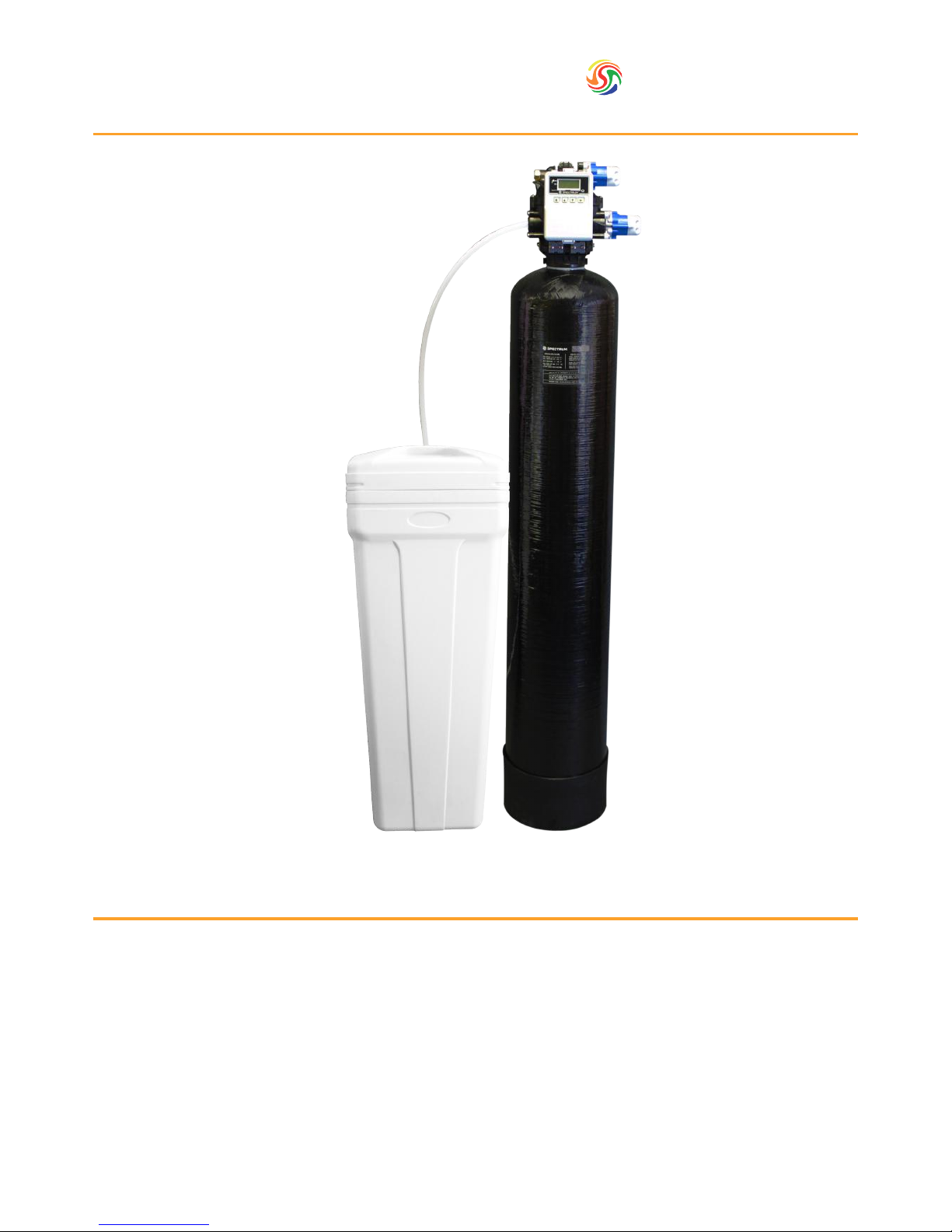
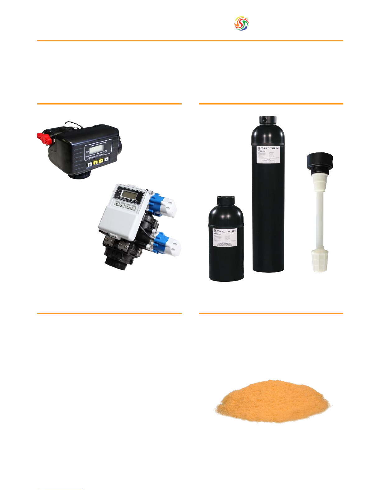
6.2. Assembly
Put the riser tube assembly into the pressure vessel if it has been removed for transport and seal the top in order to
avoid resin getting in the inside of the riser tube. Depending on sizes, the riser tube assembly will either be supplied
with a cone type screen or for bigger sizes, a star type distribution system with a hub and laterals. Once the distributor
tube is centred, ll the pressure vessel with resin, lubricate the valve distributor tube O-ring with a 100% silicone
lubricant and screw the valve onto the top of the pressure vessel. Ensure that there is no resin on the tank threads. It is
preferable to use a funnel in order to efciently ll the pressure vessel.
CAUTION: RESIN IS SLIPPERY REMOVE ANY EXCESS RESIN THAT MAY HAVE BEEN SPILT