SPEED LEADER LVP2200 User manual

User Manual
LVP2200
LED Video Processor
SpeedLeader Technology

Contents
Representation .........................................................................................................1
Trademarks ..............................................................................................................1
Safety Precautions ...................................................................................................2
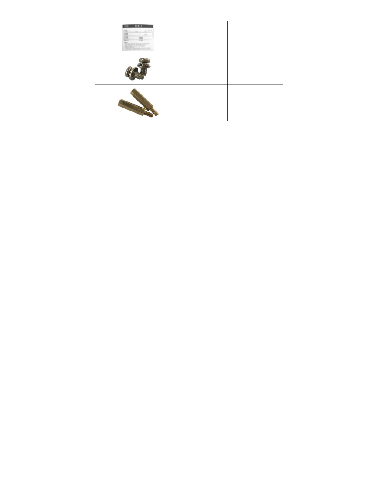
Accessories..............................................................................................................3
Model Descriptions .................................................................................................5
Overview .................................................................................................................6
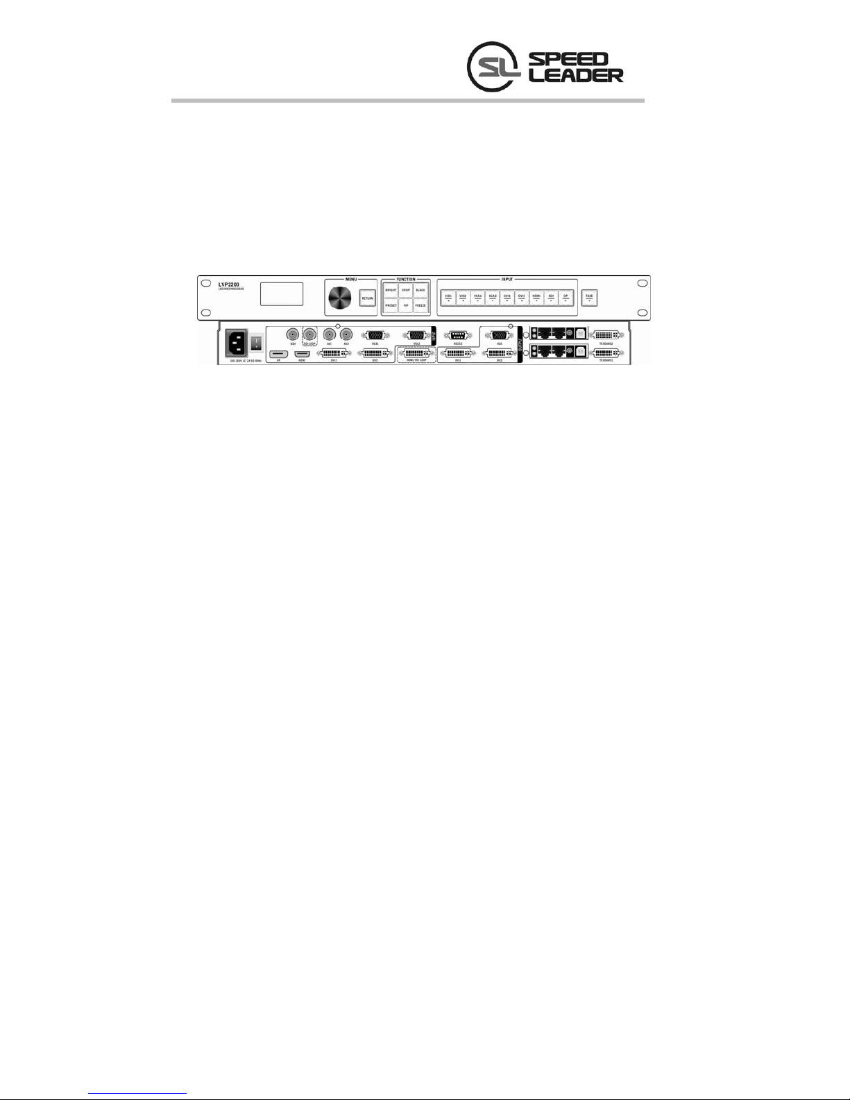
Panels ......................................................................................................................8
Front Panel ......................................................................................................8
Rear Panel........................................................................................................9
Menus ....................................................................................................................11
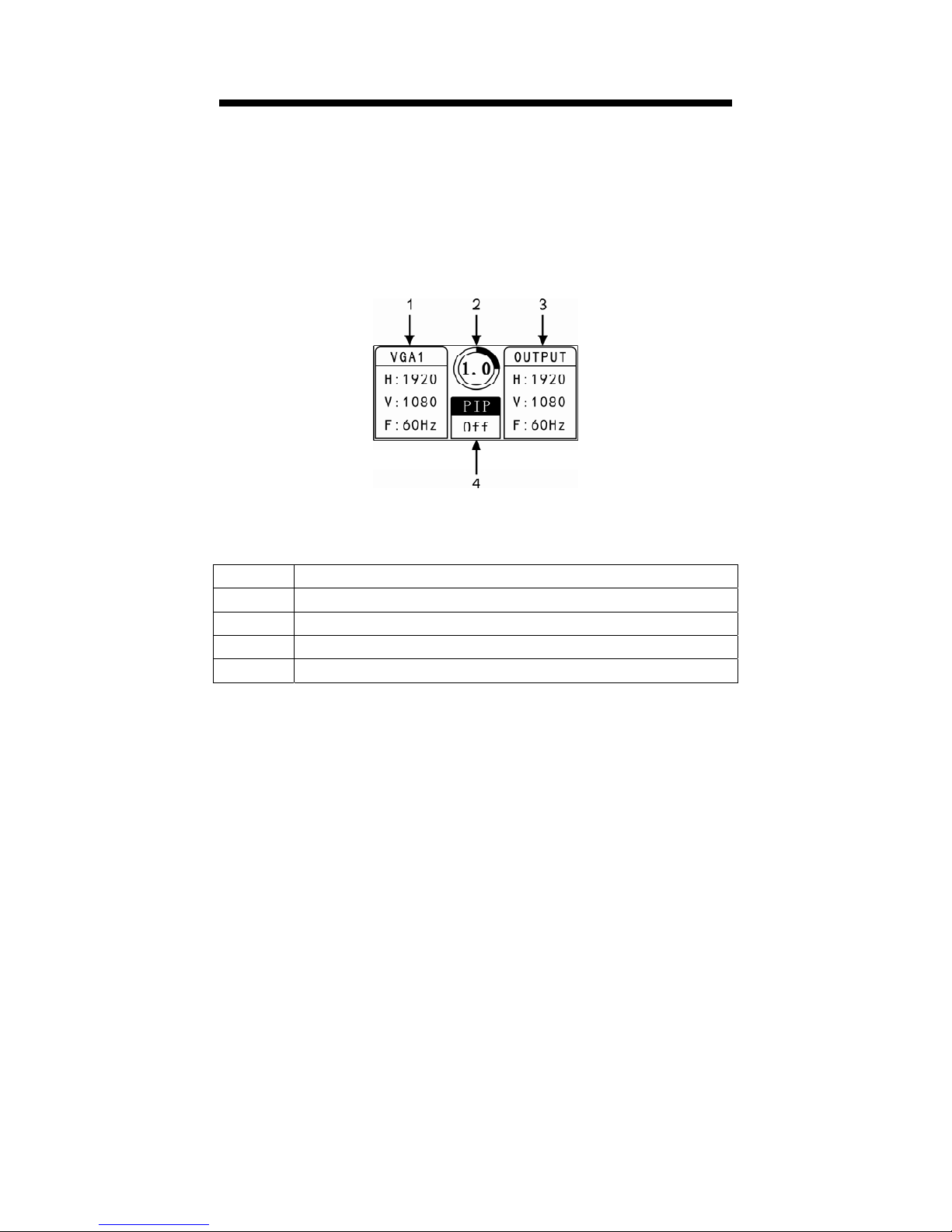
Default Menu Overview ................................................................................11
Descriptions on Main Menu ..........................................................................12
Input Menu ............................................................................................12
Output Menu..........................................................................................15
Preset Menu ...........................................................................................17
Image Menu...........................................................................................18
Function Menu.......................................................................................18
System Menu .........................................................................................20
Function Descriptions............................................................................................22
Output Resolution Settings............................................................................22
Splicing Function...........................................................................................22
Signal Connection .................................................................................23
Splicing Function Settings.....................................................................23
Equal Splicing Settings..........................................................................24
Unequal Splicing Settings .....................................................................25
PIP Mode Settings .........................................................................................26
PIP Parameter Settings ..........................................................................27
Keying Mode.................................................................................................28
Caption Add...........................................................................................28
Parameter Settings .................................................................................28

Preset Settings ...............................................................................................29
Save Preset.............................................................................................29
Erase Preset ...........................................................................................30
Load Preset ............................................................................................30
Seamless Switching/Fade-in Fade-out Settings.............................................31
Specifications ........................................................................................................33
Troubleshooting.....................................................................................................34

1
Representation
The manual must not be copied, reproduced or transcribed or translated in whole or part, or
disclosed commercially in any means (electronic, mechanical, photocopying, recording or
otherwise) or used for any commercial profit without prior written consent of our company.
Please read this manual carefully before use. Any product specification and information in
the manual are only for reference and subject to improvement without further notice. Unless
otherwise specified, the manual herein is acted as directions to use only and all statements,
information and the like do not constitute the warranty of any kind.
Trademarks
Both VGA and XGA are registered trademarks of IBM Company.
VESA is the trademark of Video Electronics Standards Association.
HDMI and High-Definition Multimedia Interface are the trademarks of HDMI Licensing LLC.

2
Safety Precautions
The equipment must be connected with ground wires.
Voltage with rated power shall be employed by the equipment and the input voltage error
shall be ±10%.
Do not connect AC power cord with another AC power cord that may cause excessive
noise.
Do not use the equipment in the environment where the temperature is -10 to 45 and℃℃
the relative humidity is 90% or below.
Do not use the equipment in the special environment, such as near heat source where the
equipment may be overheated to damage. Please use the equipment at the well-ventilated
place and keep the air vent smooth.
Do not expose the equipment at the place where the equipment may be collided
accidentally or vibrated and reinforce the equipment in case of the vibration.
Do not put such foreign objects as water and metal objects into the equipment. Otherwise,
the equipment is damaged to cause a fire.
In case of any irregular or exceptional phenomenon, cut off the power supply instantly,
disconnect the AC power cord and remove troubles in time as per "Troubleshooting".
Do not dismantle the equipment by yourself in case of any damage and contact the
designated maintenance center for repair.

3
Accessories
Table 4.1 Packing List
Items Name Quantity
LVP2200 1
Power cord 1
DVI cord 1
BNC-RCA
convertor 1
BNC-RCA
terminal 1
User manual 1
Certificate of
conformity 1

4
Warranty card 1
M3*6 round head
screws
2
Φ5*18 copper
pillars
2
*Above accessories may differ upon service condition of the user.

5
Model Descriptions
Table 5.1 Model Descriptions
Models Descriptions
LVP2200 Basic model
LVP2200S One 3G-SDI extended input; one 3G-SDI loop output

6
Overview
LVP2200 series is a high-performance LED video processor, which adopts 30-bit digital
image processing, advanced deinterlacing signal processing and truly seamless switching
technology for professional demonstration environment. It can support 1080p and
1920*1200@60Hz full high-definition outputs (up to 2304*1152@60Hz), adjust pixels in a
point-to-point manner and receive a variety of video input formats such as 3G-SDI, HDMI, DVI,
DP, VGA and standard definition video, etc.
LVP2200 series video processor supports signal interconnection and can meet super-resolution
display requirements through simple splicing settings; and there is no need to purchase the
expensive splicing controller.
Seamless fast switching or fade-in fade-out switching effect with single window or two
windows is provided to reinforce and present professional-quality demonstration images.
DVI and DP signal input resolutions, and all signal output resolutions can be defined by the
user.
The position, size, blender, color and others of the PIP (picture in picture) can be regulated.
Splicing LED Video Processor
Professional Switching Special Effect
PIP of Any Size at Any Position
User-defined Input and Output Resolutions

7
The LVP2200 series video processor, with the adoption of a high-performance 30-bit Faroudja®
DCDI image scaling engine, can convert image resolutions for the signals with different
resolutions downward or upward; at the meantime, a professional ACC and ACM image
processing engine is installed to present brand-new visions for you.
Two composite video inputs, two VGA inputs, two DVI inputs, one HDMI input, one DP input
and one 3G-SDI input (optional).
Two DVI outputs, one VGA output, one HDMI/DVI loop output and one 3G-SDI loop output
(optional).
Visualized LCD display interface, rotary knob used conveniently for control and clear key lights
make the installation and control of the system simplified.
Use shortcut keys to enter brightness and preset menus and trigger crop, PIP, black screen and
screen freeze with one key.
Input Signal
Function Keys
Broadcast-level Image Scaling Engine
Output Signal
Front Panel Used Conveniently

8
Panels
Front Panel
Fig.7.1 Panel
Table 7.1 Descriptions on Front Panel
Serial No. Name Operating instructions
1 LCD display
screen Display menus and current information.
2 Knob Select up, down, left and right menus or adjust the
parameters; press to be an enter key slightly
RETURN Return key
3
BRIGHT Image brightness adjustment shortcut key
CROP Crop switch shortcut key
BLACK Black screen shortcut key for output channel
PRESET Load preset shortcut key
PIP PIP switch shortcut key
FREEZE Window freeze or unfreeze
4
VID1 Composite video 1 source selection key, numeric key 1
VID2 Composite video 2 source selection key, numeric key 2
VGA1 VGA1 source selection key, numeric key 3
VGA2 VGA2 source selection key, numeric key 4
DVI1 DVI1 source selection key, numeric key 5
DVI2 DVI2 source selection key, numeric key 6
HDMI HDMI source selection key, numeric key 7
SDI SDI source selection key, numeric key 8
DP DP source selection key, numeric key 9

9
5 TAKE
Fade-in fade-out and seamless switching shortcut key,
numeric key 0
Rear Panel
Fig. 7.2 Descriptions on Rear Panel
Table 7.2 Descriptions on Rear Panel
Serial
No. Name Definition Descriptions/Supports
1 AC Socket Input Applied to 100V-240V AC 50/60Hz power supply
2 Power Switch “I”-On, “O”-Off
*3 SDI Output
1080p 60/50/30/25/24/25(PsF)/24(PsF)
720p 60/50/25/24
1080i 1035i
625/525 line (optional)
*4 SDI LOOP
Loop
output
5 VID1 Input
PAL, NTSC, PAL-M/N, SECAM
6 VID2 Input
7 VGA1 Input
VESA standard, PC to 1920*1200
8 VGA2 Input
9 RS232 Input
Control and update the processor via RS232 serial
port communication.
10 DP Input VESA standard, PC to 1920*1200

10
11 HDMI Input
480i/p, 576i/p, 720p, 1080i/p, support 8-bit, 10-bit
and 12-bit color depth
12 DVI1 Input
VESA standard, PC to 1920*1200
13 DVI2 Input
14 HDMI/DVI
LOOP Output
Loop out HDMI, DVI1 and DVI2 input signals, of
which the format is consistent to that of the HDMI
and DVI.
15 DVI1
Output
1024*768@60Hz 1024*1280@60Hz
1280*720@50Hz 1280*1024@60Hz
1440*900@60Hz 1024*1920@60Hz
1536*1536@60Hz 1600*1200@60Hz
1280*720@60Hz 1920*1080@50Hz
1920*1080@60Hz 1920*1200@60Hz
1680*1050@60Hz 2560*960@60Hz
2048*640@60Hz 2304*1152@60Hz
2048*1152@60H Self-defined
16 DVI2
17 VGA
18 LED sending
card position Position with the LED sending card installed
Notes: 1. All items with * mark are optional.
2. All technical parameters are subject to change without further notice.

11
Menus
Default Menu Overview
LVP2200 owns a menu system to use conveniently. Fig. 8.1 is the menu after the LVP2200 is
powered on and the signal is connected. The user can obtain the current input signal source and
output signal, as well as other important information via the menu, as shown in table 8.1.
Fig. 8.1 Default Menu
Table 8.1 Menu Descriptions
Serial No. Descriptions
1 Input channel: VGA1; Input resolution: 1920*1080@60Hz
2 Inter-channel switch time (s)
3 Resolution for output channel: 1920*1080@60Hz
4 PIP on-off state: "Off" – PIP closed; "On" – PIP opened

12
Press the knob, then the LVP2200 enters a main menu state and the LCD screen pops out a
main menu as shown in the Fig. 8.2 below. The user can press the knob to confirm and rotate it
left or right to select and adjust each item.
Fig. 8.2 Main Menu
Descriptions on Main Menu
Input Menu
At the main menu, rotate the knob, select "input" and press the knob to pop out the menu as
shown in the right of the Fig. 8.3. Here, we will introduce the five sub-menus of the input.
Fig. 8.3 Input Menu

13
①Main Image Crop
zHorizontal Width——Default: 720; Range: 0-720
zVertical Height——Default: 240; Range: 0-240
zH Start——Default: 0; Range: 0-2048
zV Start——Default: 0; Range: 0-2048
zCrop Switch——Default: Off; turn on the crop switch when modifying above parameters
zReset——Initialize above main layer crop parameters under the current channel

14
②PIP Crop
zHorizontal Width——Default: 720; Range: 0-720
zVertical Height——Default: 240; Range: 0-240
zH Start——Default: 0; Range: 0-2048
zV Start——Default: 0; Range: 0-2048
zCrop Switch——Default: Off; turn on the crop switch when modifying above parameters
zReset——Initialize above PIP layer crop parameters under the current channel
③VGA EDID
zPress the knob to enter the sub-menus of VGA EDID where 11 fixed EDID are optional
④DVI EDID
zPress the knob to enter the sub-menus of DVI EDID where 11 fixed EDID and
self-defined EDID are optional
⑤DP EDID
zPress the knob to enter the sub-menus of DP EDID where 11 fixed EDID and self-defined
EDID are optional

15
Output Menu
①Output Resolution
zPress the knob to enter the sub-menus of the output resolutions where 17 fixed output
resolutions and self-defined output resolutions are optional
②LED Panel Settings
zPanel Width——Default: 1920; Range: 0-Horizontal resolution value
zPanel Height——Default: 1080; Range: 0-Vertical resolution value
zH Start——Default: 0; Range: 0-(Horizontal resolution value– Panel width)
zV Start——Default: 0; Range: 0-(Vertical resolution value – Panel height)
zReset——Initialize above LED panel settings of the current channel

16
③PIP Window Settings
zWIN Width——Default: 950; Range: 0 ~ (Output resolution width)
zWIN Height——Default: 540; Range: 0-(Output resolution height)
zH Start——Default: 0; Range: 0-( Output resolution width – Window width)
zV Start——Default: 0; Range: 0-( Output resolution height - Window height)
zReset——Initialize above PIP window settings of the current channel
④Equal Splicing Pattern
zPattern——Equal, it means both the horizontal width and the vertical height are the same
zH Units——Default: 1; Range: 1-10
zV Units——Default: 1; Range: 1-10
zPosition——Default: 1; Range: 1-100
zReset——Initialize above parameters of the current channel at the equal splicing pattern

17
⑤Unequal Splicing Pattern
zPattern——Unequal, it means the horizontal width is different from the vertical height
zTotal Width——Default: 1920; Range: 0-(Output resolution width*10)
zTotal Height——Default: 1080; Range: 0-(Output resolution height*10)
zH Start——Default: 0; Range: 0-[( Output resolution width*10)-Total width]
zV Start——Default: 0; Range: 0-[( Output resolution height*10)-Total height]
zReset——Initialize above parameters of the current channel at the unequal splicing
pattern
Preset Menu
zSave Mode——Save all attributes of the channel so that the user can load them
conveniently
zLoad Mode——Load all attributes of the channel saved before, reducing the operation
steps of the user
zErase Mode——Erase all attributes of the channel saved before
Table of contents
Other SPEED LEADER Computer Hardware manuals
Popular Computer Hardware manuals by other brands

ekwb
ekwb EK-Nucleus AIO CR360 Vision D-RGB instruction manual

Renesas
Renesas H8S/2368 Series Hardware manual

Yamaha
Yamaha PLG100-VL owner's manual

Rittal
Rittal CMC III Processing Unit Frequently asked questions

Intel
Intel SL6NQ - Xeon 2.4 GHz/533MHz/512 KB CPU Processor... specification

National Instruments
National Instruments NI PXIe-8880 Getting started