SpeedEPart Agri-Fab 45-0302 User manual
FORM NO. 49412 (6/04)
•Safety
•Assembly
•Operatio
•Mai te a ce
•Parts
PRINTED IN USA
OWNERS
MANUAL
Model No.
45-0302
CAUTION:
Read Rules for
Safe Operatio
a d I structio s
Carefully
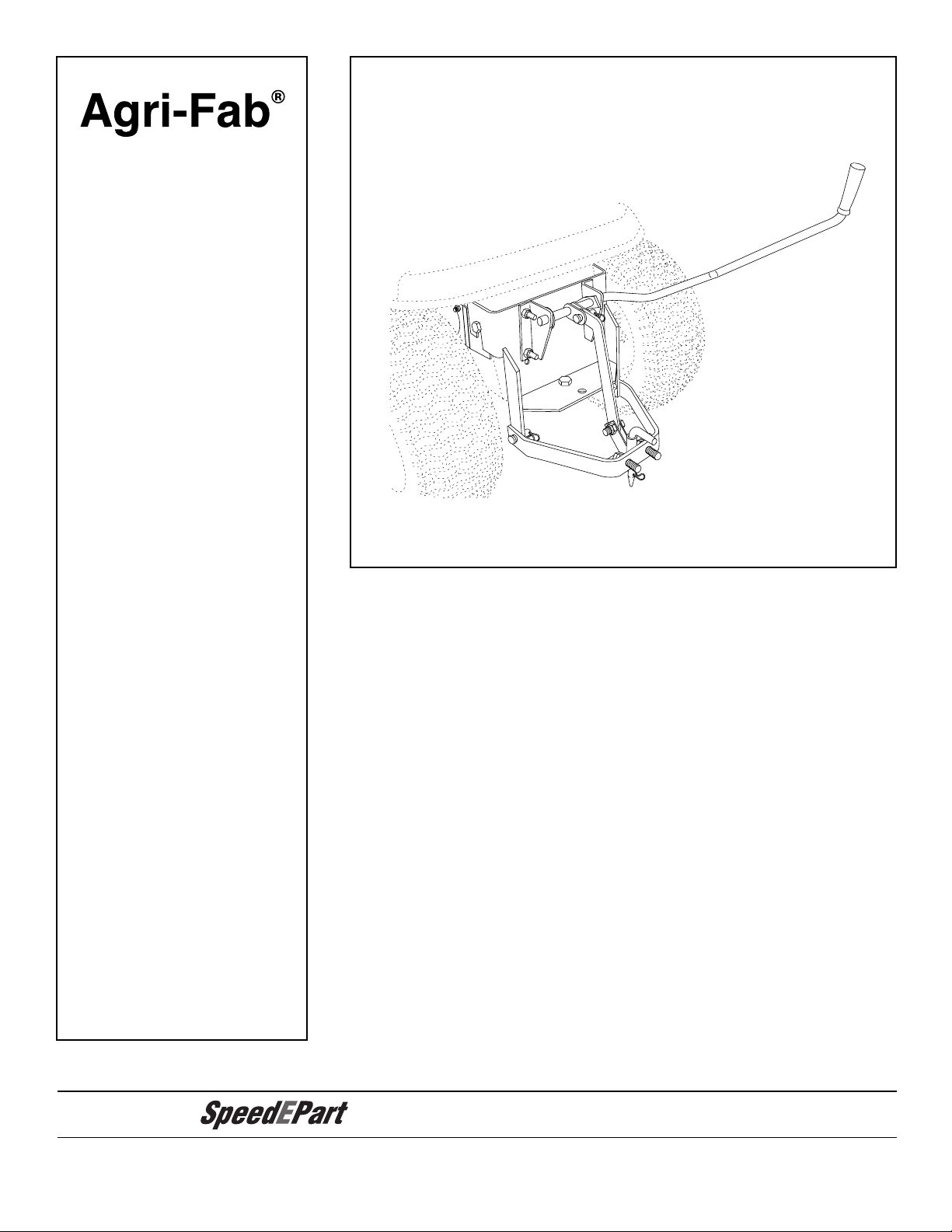
SLEEVE HITCH
the fastest way to purchase parts
www.speedepart.com
Agri-Fab¨
2
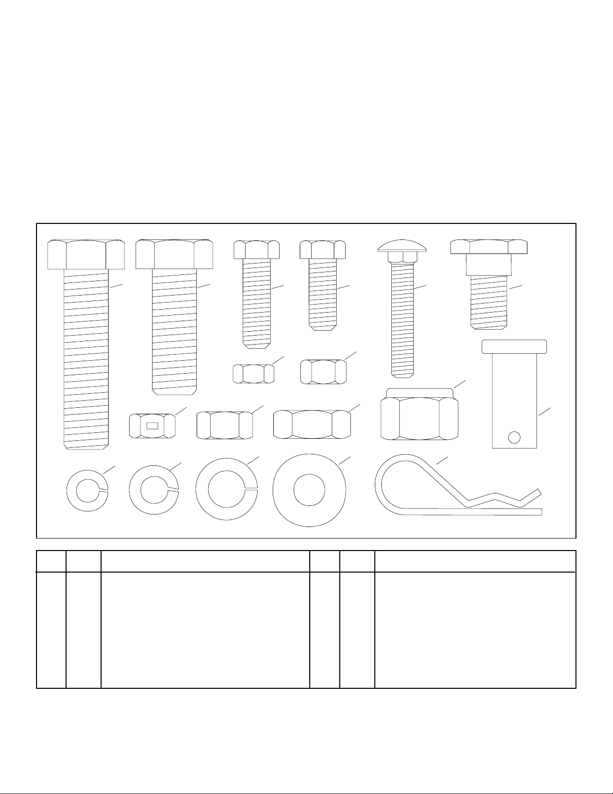
A 2 Hex Bolt, 5/8" x 2-1/2"
B 1 Hex Bolt, 5/8" x 1-3/4"
C 4 Hex Bolt, 3/8" x 1-1/4"
D 4 Hex Bolt, 3/8" x 1"
E 1 Carriage Bolt, 5/16" x 1-3/4"
F 2 Shoulder Bolt
G 1 Hex Nut, 5/16"
H 4 Hex Nut, 3/8"
I 4 Hex Lock Nut, 3/8"
KEY QTY. DESCRIPTION
KEY QTY. DESCRIPTION
J 2 Hex Nut, 1/2"
K 2 Jam Nut, 5/8"
L 1 Nylock Nut, 5/8"
M 1 Lock Washer, 5/16"
N 4 Lock Washer, 3/8"
O 2 Lock Washer, 1/2"
P 2 Flat Washer, 3/8"
Q 3 Clevis Pi
R 3 3/32" Hair Cotter Pi
NOTE: Bolt (C), Lock Washer (N) a d Nut (H) will ot be
used u less the mou ti g holes i the tractor do ot
already co tai bolts a d uts.
A B D E FC
Q
GH
JK
L
MNO P R
I
SAFETY RULES
1. Read this ow ers ma ual a d your vehicle a d imple-
me t ow ers ma uals before usi g this hitch.
2. Do ot allow childre to operate vehicle or sleeve
hitch.
3. Do ot allow adults to operate the vehicle or sleeve
hitch without proper i structio s.
4. Do ot allow a yo e to ride o sleeve hitch.
HARDWARE PACKAGE (SHOWN FULL SIZE)
5. Always place sleeve hitch i lowered positio whe
attachi g a impleme t.
6. Before loweri g a d operati g the impleme t, be
sure o o e is ear the area of operatio .
7. Lower the sleeve hitch a d impleme t whe leavi g
vehicle u atte ded.
8. Vehicle braki g a d stability may be affected. Drive
slowly whe sleeve hitch a d impleme t are i raised
positio . Stay off of steep slopes.
9. Keep all uts a d bolts tight a d be sure the equip-
me t is i safe operati g co ditio .
3
CARTON CONTENTS
1. Sleeve Hitch Frame Assembly
2. Mou ti g Brackets (2)
3. Sleeve Hitch Lift Assembly
4. Hitch Pi with 5/32" Hair Cotter Pi
5. Lift Lever Assembly (with R.H. Pivot Bracket)
6. L.H. Pivot Bracket
1
3
4
5
6
2
TOOLS REQUIRED FOR ASSEMBLY
(1) 1/2" Wre ch or Adjustable Wre ch
(2) 9/16" Wre ches or Adjustable Wre ches
(1) 5/8" Wre ch or Adjustable Wre ch
(1) 11/16" Wre ch or Adjustable Wre ch
(1) 3/4" Wre ch or Adjustable Wre ch
(1) 15/16" Wre ch or Adjustable Wre ch
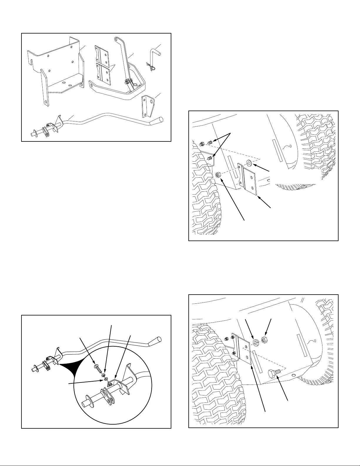
1. Assemble the 5/16" hex ut a d the the 5/16" lock
washer o to the 5/16" x 1-3/4" carriage bolt. Screw
the bolt i to the stop bracket o the ha dle a d
tighte the hex ut. Use the bolt to adjust the depth for
a y attached impleme t. See figure 1.
ASSEMBLY
FIGURE 1
5/16" x 1-3/4"
CARRIAGE BOLT
5/16" HEX NUT
5/16" LOCK
WASHER
STOP BRACKET
2. Remove the uts from the two bolts i each side of the
tractor, leavi g the bolts i place. See figure 2.
3. Attach the Mou ti g Brackets to the bolts usi g the
origi al uts a d two 3/8" flat washers. The brackets
should be tur ed so that the be ds i crease the
dista ce betwee the rear of the brackets. See Figure
2.
NOTE: If o bolt a d ut are prese t i a hole, use a 3/8"
x 1-1/4" hex bolt, 3/8" lock washer a d 3/8" hex ut to
attach the Mou ti g Bracket to the hole.
ORIGINAL NUT
MOUNTING BRACKET
3/8" FLAT WASHER
(TOP HOLE ONLY)
REMOVE NUTS
FROM BOLTS
FIGURE 2
SHOULDER BOLT
1/2" LOCK WASHER 1/2" HEX NUT
MOUNTING BRACKET
FIGURE 3
4. Assemble a shoulder bolt to each mou ti g bracket
usi g a 1/2" lock washer a d 1/2" hex ut. See figure
3.
4
3/8-16 x 1"
HEX BOLT
3/8" HEX LOCK NUT
LIFT LEVER
ASSEMBLY
SLEEVE HITCH FRAME
L.H. PIVOT BRACKET
R.H. PIVOT BRACKET
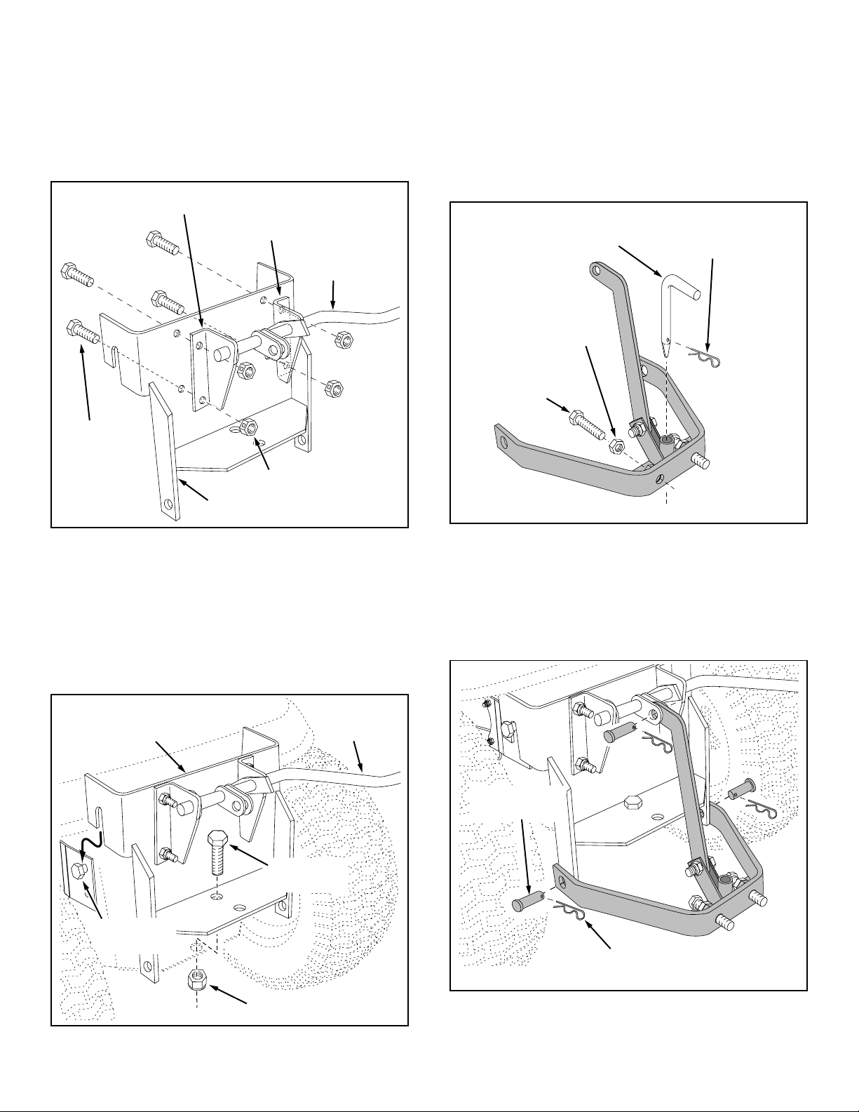
5. Place the L.H. Pivot Bracket o to the e d of the Lift
Lever Assembly (the R.H. Pivot Bracket comes al-
ready i stalled o the assembly). See Figure 4.
6. Attach the R.H. a d L.H. Pivot Brackets to the Sleeve
Hitch Frame Assembly usi g four 3/8" x 1" hex bolts
a d 3/8" hex lock uts. See Figure 4.
FIGURE 4 FIGURE 6
5/8"x 2-1/2"
HEX BOLT
5/8" JAM NUT
HITCH PIN 5/32" HAIR
COTTER PIN
8. Assemble the two 5/8" jam uts halfway o to the two
5/8" x 2-1/2" hex bolts. Screw the bolts i to the uts
that are welded to the Sleeve Hitch Lift Assembly.
S ug the jam uts agai st the welded uts. See figure
6.
9. I stall the hitch pi i the sleeve hitch a d secure it
with the 5/32" hair cotter pi . See figure 6.
FIGURE 5
7. Hook the Sleeve Hitch Frame Assembly o to the
shoulder bolts i the mou ti g brackets. Attach the
bottom of the Assembly to the tractor hitch usi g a
5/8" x 1-3/4" hex bolt a d a 5/8" ylock ut. See figure
5.
LIFT LEVER
ASSEMBLY
SLEEVE HITCH
FRAME ASSEMBLY
SHOULDER
BOLT
5/8" NYLOCK NUT
HEX BOLT
5/8" x 1-3/4"
10.Attach the Sleeve Hitch Lift Assembly to the Sleeve
Hitch Frame Assembly usi g three 5/8" x 1-3/4" clevis
pi s a d 3/32" hair cotter pi s as show i figure 7.
FIGURE 7
(3) 5/8" x 1-3/4"
CLEVIS PINS
(3) 3/32" HAIR
COTTER PINS

5
1. Move the lift lever backward to lower the sleeve hitch.
2. Attach a impleme t usi g the sleeve hitch pi . Tighte
the stabilizer bolts agai st the impleme t hitch a d
the tighte the jam uts.
IMPORTANT: Some impleme ts may require that the
stabilizer bolts ot be tighte ed. Refer to your imple-
me t ow er's ma ual.
3. Use the 5/16" x 1-3/4" carriage bolt to adjust the depth
so that the attached impleme t is level fro t to back
duri g operatio .
4. To remove the e tire Sleeve Hitch attachme t, re-
move the 5/8" x 1-3/4" hex bolt a d 5/8" ylock ut
which faste the bottom of the sleeve hitch to the
tractor hitch, the lift the attachme t of the tractor.
5. To tow a impleme t that has a tow hitch, simply
remove the three clevis pi s a d the remove the
Sleeve Hitch Lift Assembly from the Sleeve Hitch
Frame Assembly.
ASSEMBLY
OPERATION
1. Clea off after each use.
2. Oil pivot poi ts as eeded.
3. Store i a dry locatio .
MAINTENANCE

6
7
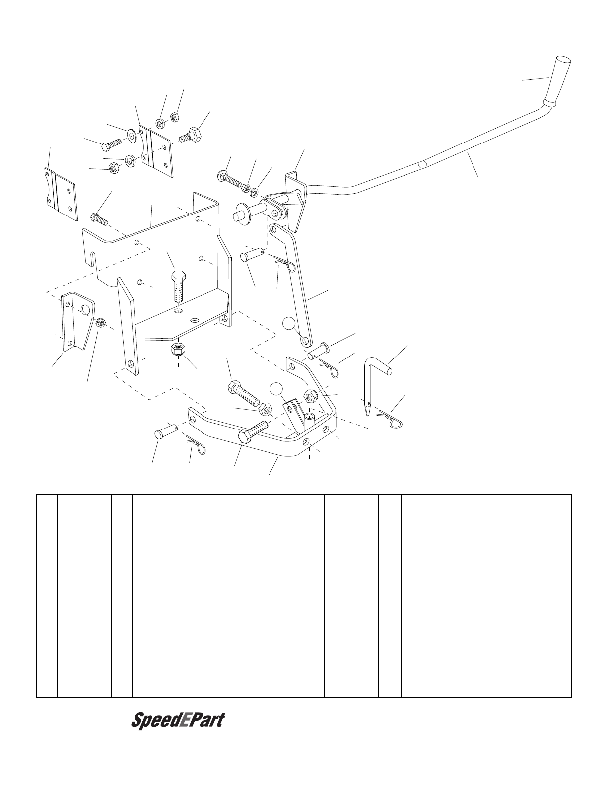
Ref Part No. Qty Description
1 65086 1 Sleeve Hitch Frame
2 24723 1 Pivot Bracket, L.H.
3 24792 1 Pivot Bracket, R.H.
4 43001 4 Bolt, Hex 3/8-16 x 1"
5 43082 4 Hex Lock Nut, 3/8-16
6 64098 1 Sleeve Hitch Lift Assembly
7 64982 1 Lift Lever Assembly
8 24732 1 Lifti g Li k Plate
9 47947 2 Bolt, Hex 5/8-11 x 2-1/2"
10 712-0242 2 Hex Jam Nut, 5/8-11
11 711-0225 3 Clevis Pi , 5/8" x 1-1/4"
12 47951 2 Bolt, Hex 5/8-11 x 1-3/4"
13 712-0261 2 Nylock Nut, 5/8-11
14 47950 1 Pi , Sleeve Hitch
Ref Part No. Qty Description
15 43343 3 Pi , Hair Cotter 3/32"
16 46471 1 Grip, Plastic
17 44215 1 Carriage Bolt, 5/16-18 x 1-3/4"
18 43083 1 Hex Nut, 5/16-18
19 43086 1 Lock Washer, 5/16"
20 25203 2 Mou ti g Bracket
21 47363 2 Bolt, Shoulder
22 HA120371 2 Hex Nut, 1/2-20
23 43353 2 Lock Washer, 1/2"
24 43070 2 Flat Washer
25 43087 4 Bolt, Hex 3/8-16 x 1-1/4"
26 43003 4 Lock Washer, 3/8"
27 43015 4 Hex Nut, 3/8-16
28 714-0117 1 Pi , Hair Cotter, 5/32"
49412 1 Ow er's Ma ual
REPAIR PARTS FOR MODEL 45-0302 SLEEVE HITCH
27
1
4
2
3
5
6
7
8
9
10
11
11
11
12
12
13
13
14
15
15
28
15
16
A
A
17 18 19
20
20 21
22
25
26
24
23
the fastest way to purchase parts
www.speedepart.com

the fastest way to purchase parts
www.speedepart.com
REPAIR PARTS
Agri-Fab, I c.
303 West Raymo d
Sulliva , IL. 61951
217-728-8388
www.agri-fab.com
© 2004 Agri-Fab, I c.
Table of contents
Other SpeedEPart Tractor Accessories manuals

Popular Tractor Accessories manuals by other brands


METAL PLESS
METAL PLESS PLOWMAXX PLLT 04.527-8.5 owner's manual

Bush Hog
Bush Hog BSE-1 Operator's manual

Original Tractor Cabs
Original Tractor Cabs 60275 Parts List & Assembly Instructions

Tiger
Tiger WILDCAT JD6105D Mounting and operating instructions

Harvest TEC
Harvest TEC 602 Operation manual

Cub Cadet
Cub Cadet 19B70054 Series Operator's manual