GreenTec Scorpion S Series User manual

1. Edition 2020


3
Scorpion 4, 6 and 8
GreenTec Scorpion 4, 6 and 8
Instruction Manual
1. Edition - January 2020
Translation of the original edition into English
IMPORTANT
Make sure that the user is handed this instruction manual before using the machine
for the first time. It is important that the user fully understands the content before
using the machine.
In case of further resale of the machine, the instruction manual must be handed
over to the new owner!
The content of the instruction manual is based on information
that was valid at the time of publication.
As our products are subject to continuous development and improvement, changes in
the specifications will be made. If there is information that differs from the machine at
hand, you can receive instructions from the GreenTec After Sales department.
MANUFACTURER –NAME AND ADDRESS (a)
Merkurvej 25
DK-6000 Kolding
DENMARK
Tel. +45 75553644
Fax: +45 75554243
Mail: [email protected]
web: www.greentec.eu

4
Scorpion 4, 6 and 8
Table of contents
(Letters (x) refer to Machinery Directive 2006/42 / EU, Paragraph 1.7.4.2, sections a - u, Content of the Instruction Book))
IMPORTANT................................................................................................................................................................3
MANUFACTURER –NAME AND ADDRESS (A)..............................................................................................................3
PREFACE........................................................................................................................................................... 8
MODEL NAME (B) AND OTHER USEFUL INFORMATION.................................................................................... 9
GENERAL INFORMATION ............................................................................................................................... 10
HOW TO USE THIS INSTRUCTION MANUAL...........................................................................................................................10
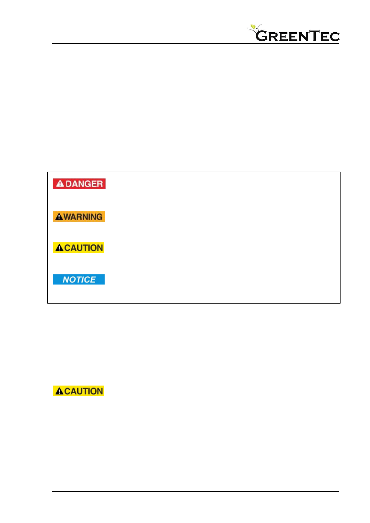
DEFINITIONS OF INFORMATION SIGNS IN THE INSTRUCTION MANUAL........................................................................................10
WHEN USING OTHER MANUFACTURERS'TOOLS WITH THE SCORPION BOOM MOWER ..................................................................10
Manufacturer's plate ......................................................................................................................................11
LOCAL LEGISLATION IN THE COUNTRY WHERE THE MACHINE IS USED.........................................................................................11
WARRANTY ..................................................................................................................................................................11
DECLARATION OF CONFORMITY (C) ............................................................................................................... 12
SAFETY........................................................................................................................................................... 13
WARNINGS,PROHIBITIONS,AND INSTRUCTIONS ..................................................................................................................13
Safety labelling................................................................................................................................................14
Labels ..............................................................................................................................................................14
INFORMATION AND WARNING LABELS................................................................................................................................15
SAFETY INSTRUCTIONS FOR ADJUSTMENT,MAINTENANCE,AND INSPECTION WORK (S).................................................................16
SAFETY INSTRUCTIONS FOR THE OPERATOR /USER................................................................................................................17
HIGH VOLTAGE LINES......................................................................................................................................................17
WORKING IN PUBLIC PLACES ............................................................................................................................................18
WARNING SIGNS IN PUBLIC PLACES....................................................................................................................................18
Suggested signage on public roads.................................................................................................................18
Further use of warning signs...........................................................................................................................18
PERSONAL SAFETY EQUIPMENT.........................................................................................................................................19
RECOMMENDATIONS FOR OPTIMAL SAFETY AND OPERATION (I)..............................................................................................19
INSTRUCTIONS ON NECESSARY PROTECTIVE MEASURES (M) ....................................................................................................20
WARNINGS:HOW NOT TO USE THE MACHINE (H) ................................................................................................................21
MACHINE INFORMATION AND SPECIFICATIONS ............................................................................................ 22
SCORPION BOOM MOWER...............................................................................................................................................22
MACHINE DESCRIPTION (D) .............................................................................................................................................22
Right/left turning models ..................................................................................................................................23
Basic version, Scorpion 4 ...................................................................................................................................23
Plus versions Scorpion 6 and 8 ..........................................................................................................................23
Strenx steel......................................................................................................................................................23
Hybrid Arm System (patent pending)..............................................................................................................23
Scorpion PLUS, RotorFlex, forward reach........................................................................................................24
4-Point mounting system (patent pending) ....................................................................................................24
Auto Hight Control (AHC) ................................................................................................................................24
Break-back ......................................................................................................................................................25
Description of the hydraulic system ................................................................................................................25
Hydraulic diagram Scorpion 4 (e)..............................................................................................................................26
Hydraulic diagram Scorpion 6 + 8 Plus (e).................................................................................................................27
CYLINDERS ON THE SCORPION....................................................................................................................... 28
The intended use of the machine (g)...............................................................................................................29
THE SCOPE OF APPLICATION AND LIMITATIONS OF THE BOOM MOWER......................................................................................30
THE ATTACHMENT TOOLS OF THE BOOM MOWER (N)............................................................................................................30
SPECIFICATIONS.............................................................................................................................................................31
SPECIFICATIONS:SCORPION 4................................................................................................................................31

5
Scorpion 4, 6 and 8
Specifications: Scorpion 6...............................................................................................................................33
MEASUREMENT OF AIRBORNE NOISE (U)...........................................................................................................................35
Results of measurement ................................................................................................................................35
OPERATING THE MACHINE (E) ....................................................................................................................... 36
OPERATOR WORKSPACES AND ERGONOMIC CONSIDERATIONS (F)............................................................................................36
OPERATIONS MANUAL....................................................................................................................................................36
USING THE LOGITEC SAFE CONTROL PANEL.........................................................................................................................37
Control panel...................................................................................................................................................37
On/off..............................................................................................................................................................37
ON / OFF..........................................................................................................................................................38
EMERGENCY STOP...........................................................................................................................................38
Temperature ...................................................................................................................................................39
AHC Auto Height Control.................................................................................................................................41
Schwimmstellung des Werkzeugs ...................................................................................................................42
Vertical cylinder 5 ...........................................................................................................................................43
AutoFlex (automatic vertical control) .............................................................................................................44
Tool startup.....................................................................................................................................................45
Hybrid arm ......................................................................................................................................................46
Cylinder functions WITH parallel motion..................................................................................................................47
Cylinder functions WITHOUT parallel motion (Hybrid activated) .............................................................................47
Control of extra equipment.............................................................................................................................49
Time indicator .................................................................................................................................................50
JOYSTICK BUTTONS.........................................................................................................................................................51
Directional movements of joystick..................................................................................................................52
INSTRUCTIONS FOR DELIVERY AND FIRST USE OF MACHINE (K)..................................................................... 53
WHEN DELIVERING THE MACHINE .....................................................................................................................................53
TRAINING OF THE OPERATOR BEFORE START-UP ...................................................................................................................54
INSTRUCTIONS FOR INSTALLATION, CONNECTING AND DISCONNECTING (J) ................................................. 55
STABILITY (O)................................................................................................................................................................55
INSTALLATION AND CONNECTION OF THE BOOM MOWER (I)...................................................................................................56
Adjusting the machine to the vehicle..............................................................................................................56
Attaching the machine to the vehicle .............................................................................................................58
Checking and readjusting the machine attachment on the vehicle ................................................................58
Fitting and installation of power take-off shaft [PTO] ....................................................................................60
Connecting the power cable............................................................................................................................61
The joystick and control panel are mounted in the cabin ...............................................................................63
Preparing boom mower for initial start-up.....................................................................................................64
Change Bottom Stop for Forward Angle .........................................................................................................65
Checking and adjusting pressure relief valves for the break-back..................................................................66
Location of pressure relief valves on Scorpion 4 .............................................................................................66
Location of pressure relief valves on Scorpion 6 and 8 ...................................................................................66
LOCATION AND FUNCTION OF SENSORS ..............................................................................................................................67
CONTROLLING THE FUNCTIONALITY OF THE BREAK-BACK........................................................................................................68
FUNCTIONAL AREAS OF THE BREAK-BACK ............................................................................................................................69
INITIAL START-UP........................................................................................................................................... 70
PROCEDURES BEFORE START-UP .......................................................................................................................................70
ADJUSTING THE BOOM MOWER TO WORKING POSITION AND OPERATION (R) ............................................ 71
ATTACHMENT TOOLS AND EXTRA EQUIPMENT ............................................................................................. 72
MOUNTING TOOLS.........................................................................................................................................................72
DEMOUNTING ATTACHMENT TOOLS ..................................................................................................................................73
MOUNTING EXTRA EQUIPMENT ........................................................................................................................................74
Mounting “quick hitch”...................................................................................................................................75

6
Scorpion 4, 6 and 8
Mounting weight blocks..................................................................................................................................76
Hydraulic quick release coupling.....................................................................................................................77
Mounting leaf blower .....................................................................................................................................78
PREPARING THE MACHINE FOR TRANSPORT.................................................................................................. 79
INITIAL START-UP AND DRIVING WITH THE TOOLS ........................................................................................ 80
PROCEDURE FOR GETTING THE BOOM MOWER IN WORKING POSITION......................................................................................80
STARTING UP THE TOOL ..................................................................................................................................................81
Tool start-up procedure ..................................................................................................................................81
TURNING OFF THE TOOL..................................................................................................................................................82
INSPECTION AND MAINTENANCE (E, R) ......................................................................................................... 83
SAFE MAINTENANCE AND ADJUSTMENT INSTRUCTIONS (S)....................................................................................................83
DAILY/ROUTINE INSPECTION (E) .......................................................................................................................................84
TABLE 5-DAILY INSPECTION OF THE ENTIRE MACHINE BEFORE START-UP..................................................................................84
HALF-YEARLY INSPECTION,PREVENTIVE MAINTENANCE .........................................................................................................84
PERIODIC INSPECTIONS ...................................................................................................................................................85
THE INDIVIDUAL COMPONENTS.........................................................................................................................................86
Gearbox...........................................................................................................................................................86
PTO shaft.........................................................................................................................................................86
The Hydraulic system ......................................................................................................................................86
Tank ..........................................................................................................................................................................87
The hydraulic oil........................................................................................................................................................87
Danfoss valves...........................................................................................................................................................88
Hoses and fittings .....................................................................................................................................................88
Filters ........................................................................................................................................................................88
Pressure filter consists of:........................................................................................................................................88
Replacing the filter element: ....................................................................................................................................89
LUBRICATION................................................................................................................................................................90
TROUBLESHOOTING THE MACHINE AND START-UP AFTER SHUTDOWN (Q) .................................................. 91
TROUBLESHOOTING PROCEDURES .....................................................................................................................................91
Use Auto Height Control (AHC) more. Read the section AHC Auto Height Control.........................................91
Read the section Fejl! Henvisningskilde ikke fundet. ......................................................................................91
Pump and engine failure .................................................................................................................................93
STARTING UP AFTER SHUTDOWN.......................................................................................................................................94
TABLE LIST
TABLE 1–OVERVIEW AND FUNCTIONS OF HYDRAULIC CYLINDERS,SEE ALSO FIGURE 11 ..............................................................25
TABLE 2-SPECIFICATIONS SCORPION 4 .............................................................................................................................32
TABLE 3-SPECIFICATIONS SCORPION 6 .............................................................................................................................34
TABLE 4–EXTRA EQUIPMENT..........................................................................................................................................74
TABLE 5-DAILY INSPECTION OF THE ENTIRE MACHINE BEFORE START-UP..................................................................................84
TABLE 6-HALF-YEARLY INSPECTION,PREVENTIVE MAINTENANCE............................................................................................84
TABLE 7–PERIODIC INSPECTION OF THE ENTIRE MACHINE.....................................................................................................85
TABLE 8–TROUBLESHOOTING.........................................................................................................................................92

7
Scorpion 4, 6 and 8
FIGURES
FIGURE 1-MODEL NAME (B)AND RETAILER INFORMATION .....................................................................................................9
FIGURE 2–GREENTEC CONTACT INFORMATION ....................................................................................................................9
FIGURE 3-DEFINITIONS OF INFORMATION SIGNS IN THE INSTRUCTION MANUAL ........................................................................10
FIGURE 4-MANUFACTURER'S PLATE.................................................................................................................................11
FIGURE 5-SAFETY LABELLING WARNING SIGNS ..................................................................................................................14
FIGURE 6-INFORMATION AND WARNING LABELS................................................................................................................15
FIGURE 7-PERSONAL SAFETY EQUIPMENT .........................................................................................................................19
FIGURE 8-ILLUSTRATION OF THE SCORPION BOOM MOWER ..................................................................................................22
FIGURE 9–THE ARM CAN MOVE 155°ON THE PLUS SERIES ........................................................................................24
FIGURE 10 –THE ARM CAN MOVE 105°ON THE STANDARD SERIES.........................................................................................24
FIGURE 11 –HYDRAULIC DIAGRAM SCORPION 6+8PLUS ....................................................................................................27
FIGURE 12 -LOCATION AND DESCRIPTION OF CYLINDERS ON THE MACHINE...............................................................................28
FIGURE 13 -SPECIFICATIONS OF CONTROL PANEL ................................................................................................................37
FIGURE 14 -CYLINDER FUNCTIONS WHEN USING PARALLEL MOTION........................................................................................47
FIGURE 15 -CYLINDER FUNCTIONS WITHOUT PARALLEL MOTION (HYBRID ACTIVATED).............................................................48
FIGURE 16 -JOYSTICK BUTTONS ON SCORPION 4.................................................................................................................51
FIGURE 17 -JOYSTICK BUTTONS ON SCORPION 6+8.............................................................................................................51
FIGURE 18 -DIRECTIONAL MOVEMENTS OF JOYSTICK............................................................................................................52
FIGURE 19 -SHIPMENT OF SCORPION 6-8 .........................................................................................................................53
FIGURE 20 -SHIPMENT OF SCORPION 4.............................................................................................................................53
FIGURE 21 -MOUNTING THE TOP PART OF THE MACHINE ON A VEHICLE (SHOWN HERE WITH K80 BALL HITCH)................................57
FIGURE 22 -MOUNTING OF THE MACHINE'S 4-POINT MOUNTING SYSTEM AND THE VEHICLE'S LOAD-CARRYING BALL HITCH...............57
FIGURE 24 –SLACK ADJUSTMENT OF PILOT BALL JOINTS........................................................................................................58
FIGURE 25 -MACHINE SUPPORT LEGS ...............................................................................................................................59
FIGURE 25 -LUBRICATION OF PTO...................................................................................................................................60
FIGURE 26 -MOUNTING OF SAFETY CHAINS........................................................................................................................60
FIGURE 27 -MACHINE POWER CABLE................................................................................................................................61
FIGURE 28 -CONNECTING THE POWER CABLE TO THE BATTERY OF THE VEHICLE .........................................................................61
FIGURE 29 -ELECTRICAL CONNECTION OF MACHINE .............................................................................................................62
FIGURE 30 -PLACEMENT OF REMOTE CONTROL AND JOYSTICK................................................................................................63
FIGURE 31 –BACKSTOP,FLAT -0DEGREES,TRIANGLE 5DEGREES OR TRIANGLE 10 DEGREES .......................................................65
FIGURE 32 -PRESSURE RELIEF VALVES ON SCORPION 4.........................................................................................................66
FIGURE 33 -PRESSURE RELIEF VALVES ON SCORPION 6AND 8................................................................................................66
FIGURE 34 -LOCATION OF INDUCTIVE SENSORS...................................................................................................................67
FIGURE 35 -FUNCTIONAL AREAS OF THE BREAK-BACK...........................................................................................................69
FIGURE 37 –THE NORMAL ANGLE OF THE “QUICK HITCH“SYSTEM.NOTE THAT THE CYLINDER IS FULLY CONTRACTED ........................75
FIGURE 38 -CONTENTS OF THE “QUICK HITCH”SYSTEM ........................................................................................................75
FIGURE 38 –WEIGHT-BLOCK CASING FOR SCORPION 4AND SCORPION 6-8 .............................................................................76
FIGURE 40 -WEIGHT BLOCKS ..........................................................................................................................................76
FIGURE 41 -QUICK COUPLINGS -STATIONARY PART.............................................................................................................77
FIGURE 41 -SET OF QUICK RELEASE COUPLINGS WITH WASHERS .............................................................................................77
FIGURE 42 -MOUNTING LEAF BLOWER..............................................................................................................................78
FIGURE 43 -EXAMPLE OF OPTIMAL TRANSPORT POSITION OF SCORPION 6PLUS,WITH MOUNTED PIVOT JOINT AND FLAIL MOWER ......79
FIGURE 44 -LUBRICATION INSTRUCTION FROM THE PTO INSTRUCTION MANUAL .......................................................................86
FIGURE 46 –HYDRAULIC TANK WITH MAX/MIN INDICATORS..................................................................................................87
FIGURE 47 –O-RINGS AND FILTER ELEMENT ON THE PRESSURE FILTER .....................................................................................88
FIGURE 48 –O-RING,FILTER ELEMENT AND AIR FILTER ON THE RETURN FILTER ..........................................................................88

8
Scorpion 4, 6 and 8
Preface
Dear Customer!
Your new GreenTec machine is designed based on more than 25 years of
experience with tractor mounted machines for the maintenance of green areas.
The machine is manufactured from the latest technology and in accordance with
approved safety regulations, standards, and requirements.
We want to provide a product where no damages or misunderstandings occur
during operation, transport, or maintenance of the machine. The instruction
manual contains information and instructions that are important and useful for
maintaining the operational reliability and value of the GreenTec machine.
Therefore, read this manual carefully as it will familiarize you with mounting,
proper use, care, and maintenance.
Pay special attention to safety instructions.
You are welcome to visit our website www.greentec.eu - where you can use the
retailer login to access the latest updates of instruction manuals and spare parts
catalogues for our whole product line.
We hope you will be pleased with your new GreenTec machine.
Kind regards
John Christensen
Sales Director GreenTec A/S
GreenTec's vision is to develop and sell quality machines for the maintenance of
green areas, for example in agriculture, industry, airports, and the municipal sector.
Through innovative product development, we strive to become a leader in our field.
All machines are developed in a simple and functional design in close cooperation with
retailers and end users. Our goal is to uncover all needs in the market segment,
preferably with two different solutions. Through in-depth requirement analyses and
quality counselling, the customer is offered the best solution, where individual
requirements can also be met through modular configuration of the product program.
We also aim to offer the best possible after sales service and a fast and efficient spare
parts supply.

9
Scorpion 4, 6 and 8
Model name (b) and other useful information
The first time the machine is used, the seller is responsible for giving the buyer this
instruction manual. In addition, he/she must ensure that the buyer fully understands
the content before proceeding If the machine is resold, the instruction book must be
handed over to the new owner.
The following fields are filled in for use when ordering spare parts or other inquiries.
Model name
Serial number
Date of delivery
Retailer
Mail
Phone
Figure 1 - Model name (b) and retailer information
Figure 2 –GreenTec contact information
Merkurvej 25
DK-6000 Kolding
Denmark
Tel. +45 75553644
Fax: +45 75554243
Mail: [email protected]
Web: www.greentec.eu
Opening hours: Monday-Friday 8-16 Uhr

10
Scorpion 4, 6 and 8
General information
How to use this instruction manual
Read this instruction manual carefully before mounting and deploying the machine. If
any doubts arise, contact your local retailer or the GreenTec After Sales department.
To maintain GreenTec's 2-year warranty, as well as product liability insurance, only
use original GreenTec spare parts on GreenTec machinery and equipment.
Definitions of information signs in the instruction manual
The following definitions apply to this entire instruction manual:
DANGER: Warns of a potential situation that can result in death or
permanently invalidating injuries if the instructions are not carefully
followed.
WARNING: Warns of a potential situation that can result in partially
invalidating injuries or grievous bodily harm if the instructions are
not carefully followed.
CAUTION: Warns of a potential situation that can result in serious
damages to machine or equipment if the instructions are not
carefully followed.
NOTICE: Specific or general information that is deemed important
or useful.
Figure 3 - Definitions of information signs in the instruction manual
Left Hand (LH) & Right Hand (RH)
These terms are used when the machine is mounted on the vehicle seen from behind.
The terms are also used when referring to the vehicle.
When using other manufacturers' tools with the Scorpion boom mower
When mounting other components on the Scorpion boom mower
other than the GreenTec tools covered by the declaration of
conformity, the basis of the risk assessment will be annulled, and thus the validity of
the declaration of conformity. In that case it is the operator's own responsibility to
carry out a new risk assessment.

11
Scorpion 4, 6 and 8
Manufacturer's plate
All machines are equipped with a manufacturer's plate that contains important
information related to the machine, including a unique serial number used for
identification.
Figure 4 - Manufacturer's plate
Local legislation in the country where the machine is used
The use of the machine may be restricted by the laws of the individual countries. It is
important that the responsible owner or works manager is familiar with the country's
laws and regulations regarding cutting, trimming and general maintenance of hedges
and shrubbery.
Warranty
GreenTec is not liable for damage sustained by unlawful or incorrect use of the
Scorpion machine.
See also GreenTec's warranty terms (no. 5) in the ‘Terms and Conditions of Sale and
Delivery’:
https://greentec.eu/en/terms-and-conditions-sale-and-delivery/
NOTICE
The symbols in this manual are for the sole purpose of instructing and informing - not
illustrating the components in their entirety. Under special circumstances, the symbols
may appear different from the current machine. When this occurs, the general
procedure will be the same.

12
Scorpion 4, 6 and 8
Declaration of conformity (c)
In Machinery Directive 2006/42/EC, Annex II.A
Manufacturer: GreenTec A/S
Address: Merkurvej 25
Zip code and City: DK-6000 Kolding
We, GreenTec A/S, declare, with all responsibilities, that the machine:
Type
Product
Models
Boom mower
Scorpion 4
(Compact)
330-4 S (rear + front mounted)
430-4 S (rear + front mounted)
Scorpion 6
530-6 S (rear + front mounted)
530-6 S Plus (rear + front mounted)
630-6 S (rear + front mounted.)
630-6 S Plus (rear + front mounted)
Scorpion 8
703-8 S (rear + front mounted)
703-8 S Plus (rear + front mounted)
803-8 S (rear + front mounted)
803-8 S Plus (rear + front mounted)
Tool
Flail mower
FR 92 (40 l/min), FR 112 (40 l/min), FR 122 (60 PS +90 PS)
FR 122 HD (60 PS + 90 PS), FR 162(60 PS + 90 PS)
FR 162 HD (60 PS + 90 PS)
Tool
Cutter bar
HX170, HX230, HX270
Tool
Hedge cutter
HL152, HL182, HL212, HL242
Tool
Hedge cutter bar
HS172, HS212, HS242
Tool
Barrier mower
RI60, RI80
Tool
Grass cutter bar
S165, S190, S240
Tool
Quadsaw
LRS1402, LRS1602, LRS2002, LRS2402
Tool
Rotary hedge cutter
RC102, RC132, RC162
Tool
Rotary mulcher
RM 232
Tool
Rotary crusher
GT135, GT155
Tool
Ditch cleaner
GR70
Tool
Weed brushes
BR70, BR90
Tool
Rotary rake
KR250
Tool
Leaf blower
LG
that the machine is manufactured in accordance with Directive 2006/42 / EC of the European
Parliament and the Council of Europe, with reference to the following standards associated with its
design, construction, and production:
DS/EN ISO 12100:2011 Safety of machinery - General principles for design - Risk assessment and
risk reduction
DS/EN 14120:2015 Safety of machinery - Guards - General requirements for
the design and construction of fixed and movable guards
DS/EN ISO 4413:2010 Hydraulic fluid power - General rules and safety requirements for systems
and their components
The declaration applies to the above-mentioned equipment, including the machine’s connections -
mounting and stabilization systems, respectively - power take-off and electrical connections.
When connecting the above-mentioned equipment to a vehicle and other tools than those mentioned
above, it is the responsibility of the user to ensure that the vehicle and the overall machine comply with
the applicable requirements in the relevant directives for this purpose.
Date: 18.01.2020 Signature:___________________________
John Christensen - Sales Director

13
Scorpion 4, 6 and 8
Safety
The instructions derive from the current national accident prevention regulations that
the owner or the operational manager must comply with.
Just as the current traffic laws, of course, must be complied with if the machine is
used on public roads.
Warnings, prohibitions, and instructions
For any kind of work on the tool, it must be disconnected from
all hydraulics.
Only authorized personnel may perform service work on the
tool.
Read this instruction manual carefully before putting the tool
into use.

14
Scorpion 4, 6 and 8
Safety labelling
The machine is affixed with safety labels, these are placed at the identified dangers
that the user is exposed to while working with or being near the machine.
Labels
Warning
Before carrying out any
maintenance or repairs on
the machine: Switch off the
engine, remove the ignition
key and pull the handbrake.
Warning
Read the instructions
manual carefully before
using this machine. Follow
all instructions and safety
precautions when using the
machine.
Warning
Rotating power take-off
shaft (PTO). Before
operating:
Switch off the engine,
remove the ignition key and
pull the handbrake.
Warning
Check every 8 hours that all
bolts / nuts are tightened.
Warning
There is a danger of getting
crushed or hit when the
machine is running.
No one is allowed in the
work zone.
Warning
Oil under high pressure -
Be careful to avoid skin
contact / inhalation of
fumes when handling - or in
case of a leak.
Warning
Always be aware of
overhead lines. There will
always be a risk of
touching the overhead
lines. In case of doubt -
contact the local power
plant for instructions on
safety distances.
Warning
There is a danger of getting
crushed when the machine
is mounted on the vehicle.
No one is allowed between
the vehicle and the tool.
Figure 5 - Safety labelling Warning Signs

15
Scorpion 4, 6 and 8
Information and warning labels
Scorpion 4 rear mounted
Scorpion 4 front mounted
Scorpion 6+8 rear mounted
Scorpion 6+8 front mounted
4X transportation locks for all
Scorpion models.
Both front and rear mounted - as
well as right and left models
•The outer top valve blocks
cylinder 3 (in and out
movement)
•The outer bottom valve
blocks either cylinder 5 or the
rotor cylinder (for tilting the
tool)
•The inner top valve blocks
cylinder 1 (for arm rotation)
•The inner bottom valve
blocks cylinder 2 (for lifting
and down)
Figure 6 - Information and warning labels

16
Scorpion 4, 6 and 8
Safety instructions for adjustment, maintenance, and inspection work (s)
•The operator must ensure that all maintenance, inspection, and installation work is
carried out by authorized and qualified professional personnel who, after carefully
reading the instruction manual, have sufficient knowledge
•Maintenance, inspection, and assembly work must only be carried out when
hydraulics is disconnected.
•For maintenance work under the tool carrier, secure with appropriate support
elements.
•When replacing attachment tools, check the hydraulic system for residual pressure
- any remaining residual pressure is reduced to zero (0 bar).
•Use only suitable maintenance and adjustment tools and wear safety work gloves,
safety shoes and safety goggles.
•Handle the hydraulic oil and grease in compliance with regulations. Be familiarized
with the safety data sheets.
•Immediately after the completion of work, all safety devices must be installed and
reactivated.

17
Scorpion 4, 6 and 8
Safety instructions for the operator / user
•It is important to familiarize yourself with all equipment, the elements of service
and their function before starting up work. If your work has started, it is too late.
•The user's clothing must be tight-fitting. Avoid loosely fitted clothes.
•Check the area before start-up (children / obstacles, for example stones, fences,
steel wire). Ensure adequate visibility and properly lighted conditions. The safety
distance specified in the tool's instruction manual must be followed unconditionally.
•The user must be fully rested before using the machine - and take a break if
he/she feels tired, to ensure the safety of him/herself and others.
•The user should ensure variation in working positions and take frequent breaks to
avoid musculoskeletal disorders.
•It is not permitted to be on - to 'ride along' or in any other way - the tool or machine
during transportation and work.
•When operating, never leave the driver's seat.
•When operating under high voltage lines, extra distance and caution is required.
High voltage lines
Always be aware of overhead lines. Between
power pylons there will always be a risk of touching the
overhead lines.
In case of doubt - contact the local power plant for instructions on
safety distances.

18
Scorpion 4, 6 and 8
Working in public places
When working in public places, such as roadsides, careful consideration should be
shown to others in the area. Stop the machine immediately when, for example,
pedestrians, cyclists, and riders pass by. Do not resume work until the passer-by is
again at safe distance.
Warning signs in public places
The work area should be marked with appropriate signs as this is legal
requirement in public places. Signage must be clearly and correctly
placed so that the danger is clearly visible.
Contact the Road Directorate for detailed information on current
regulations. The Road Authority must be advised before commencing
work on public roads.
- Time and place must be announced.
Suggested signage on public roads
•Warning Sign: "Road work" with additional, specifying sign, for example "Verge
cutting". "0-1 km" or appropriate shorter distance.
•Warning Sign: “Road chicane” with the additional "One lane only“.
•Command sign: "Hold left" White and blue arrow sign on the back of the machine (*).
* This applies within the EU where traffic passes left of the machine
working in the traffic direction. The indications, use, and colours of arrow signs depend
on the laws and regulations of each country.
Further use of warning signs
•On two-way roads, signs are placed in both directions.
•The work should be within 1 km. of signage.
•Only perform work when visibility is good and when the risk is small - for example
outside rush hour.
•The vehicle must be equipped with a flashing light bar.
•Vehicles should be in eye-catching colour.
•Material residue should be removed from the road and sidewalk as quickly as
practically possible and at appropriate intervals. This work must be done before
warning signs are removed and the personnel must wear visible clothing.
•Collect all road signs as soon as the work is completed.

19
Scorpion 4, 6 and 8
Personal safety equipment
It is recommended that the following safety equipment be worn when working with or
performing maintenance work on the machine.
Figure 7 - Personal safety equipment
The recommended safety equipment along with the special points of attention
mentioned in the following sections cover the precautions GreenTec has considered
necessary.
The varying circumstances that may arise during work with this machine cannot
always be foreseen. No good advice can replace "common sense" and "awareness" at
any time, but the above-mentioned is a good start for the safe use of your GreenTec
machine.
Recommendations for optimal safety and operation (I)
For optimum safety and operation, it is important that the user understands how
dangerous the machine is.
Be aware of the following risks
You can get stuck when the machine is being connected or disconnected and when the
arm is moving in or out, up, or down, forwards, or backwards.
The machine can tip when the arm is raised.
You can get caught by the rotary axle from the power take-off.
You can be hit or trapped by the moving parts, for example blades, driving axle and wings
from mounted tools.
You can be hit by flying materials or machine parts in the event of damage.
The machine can tip over when not in use.
The mounted tool is powered by hydraulic oil from the vehicle. The driver of the vehicle
should be aware of how to handle the oil (see the oil’s safety data sheet).
Oil splashes under high pressure from damaged joints or hydraulic hoses can penetrate
the skin and cause serious harm.
Accidents, for example a collision with another machine or lost objects on the road.
Boiler suit
Safety boots
Safety goggles
Hearing
protection
Safety helmet
Safety work
gloves

20
Scorpion 4, 6 and 8
Instructions on necessary protective measures (m)
The machine must always be used in the following way
Make sure that the driver of the machine has read this manual and "user statement" and
has been instructed in the use of the machine.
Use hearing protection if the machine is operated from a cabin that is not soundproof or if
the cabin windows are open.
Make sure that all warning labels are always visible and that none of them are missing or
damaged / unreadable.
Check the work area and remove any string, poles, large rocks, or other hazardous
objects before commencing work.
Make sure that the vehicle is stable and that it meets all the machine manufacturer's
recommendations for maximum weight when mounting tools
- if necessary, use additional counterweight.
Drive at a safe speed that is adjusted to the terrain and any other vehicles or obstacles.
Be aware of electric wiring. If in doubt, contact the local power plant.
It is recommended to use impact-resistant guards on the vehicle.
Make sure that all guards are installed correctly and that there are no damaged or loose
parts.
Make sure that all hydraulic pipes and hoses are correctly positioned to avoid rubbing,
stretching or crack damages.
Check that the machine fittings, joints, and couplings are in good condition.
Follow the manufacturer's instructions when mounting and dismounting the machine from
the vehicle.
Turn off the hydraulics, stop the engine, pull the handbrake, and remove the ignition key
before leaving the cabin.
If necessary, remove the residual material from the area.
For inspection, repairs. or other work on a stationary machine, very cautious behaviour is
necessary. Always use gloves, safety glasses and suitable tools for the work.
This manual suits for next models
11
Table of contents
Other GreenTec Tractor Accessories manuals