SPEEDY-LIFT SP-HDA11 User manual
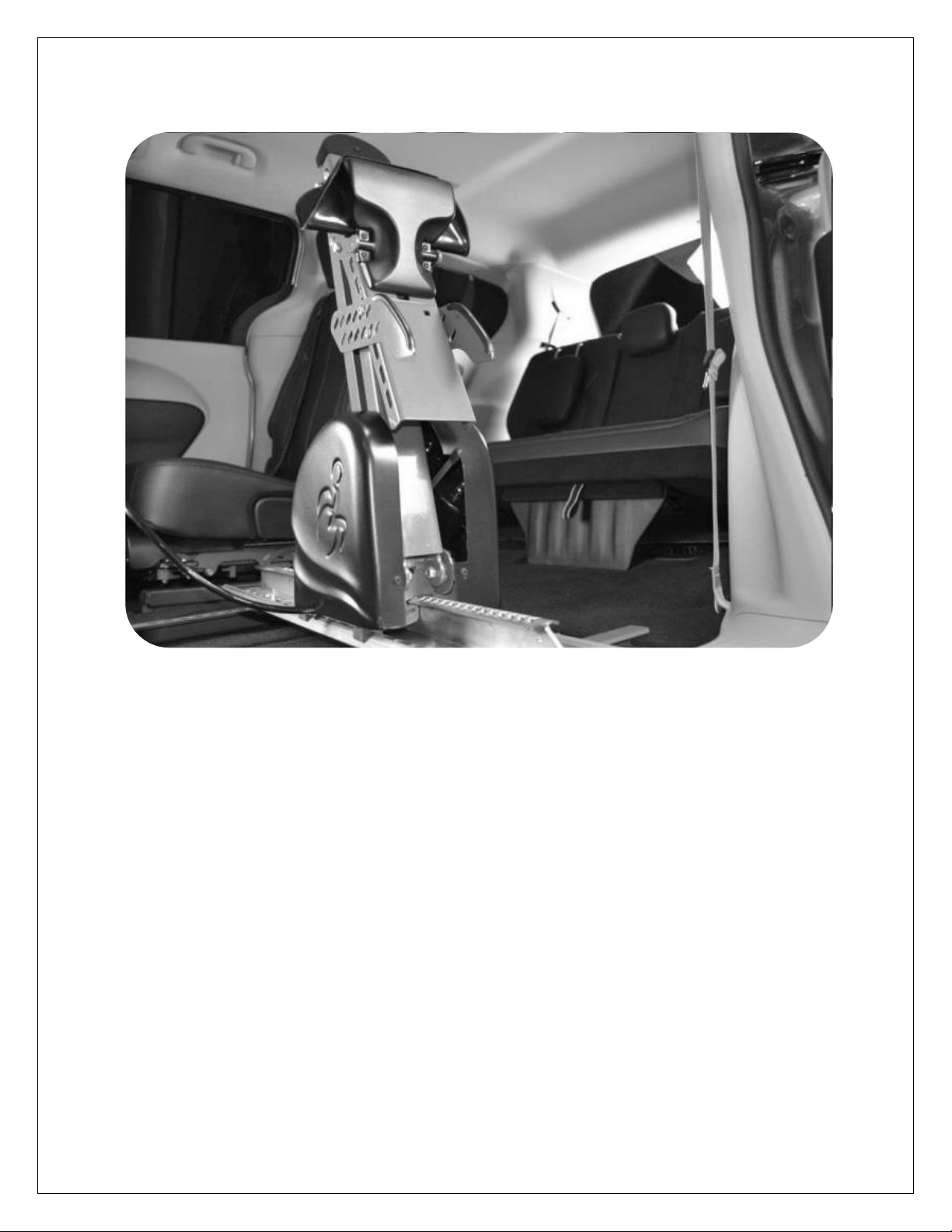
SPEEDY-LIFT
INSTALLATION MANUAL
SP-HDA11
HONDA ODYSSEY
2011-2017
1 of 5
ITEM
PART NUMBER
QTY
DESCRIPTION
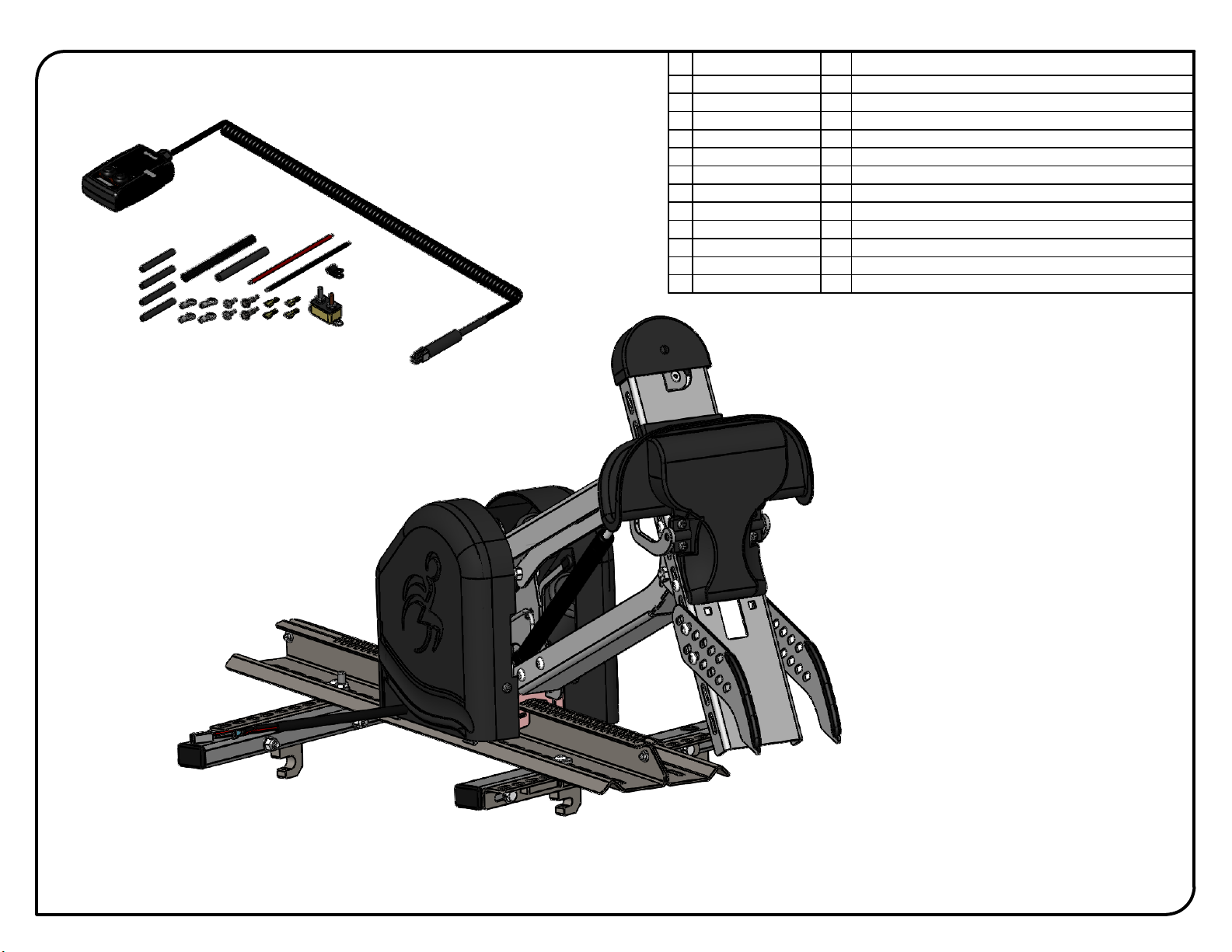
1
SP000
1
Mechanism Assembvly
2
SP100-01
1
Rail Assembly
3
SP600B
1
Housing Cover Assembly -Black-
4
SP700B
1
Hook Assembly -Black-
5
SP740
2
Wheelchair support
6
SL800
1
Electrical Kit -Alone-
7
PRD 110-104
4
Round washer head tapping screw #8 x 1/2
8
PRD 302-100P
1
Hex Cap Bolt Zinc Plated 1/4-20 x 1/2 G5
9
PRD 333-105M
1
Nylon Insert Locknut 1/4-20 Thin
10
PRD 337-211P
10
Button Head Socket Cap Screw Zinc Plated 5/16-18 x 1/2
11
PRD 2946
4
Flange Locknut Zinc Plated 5/16-18
12
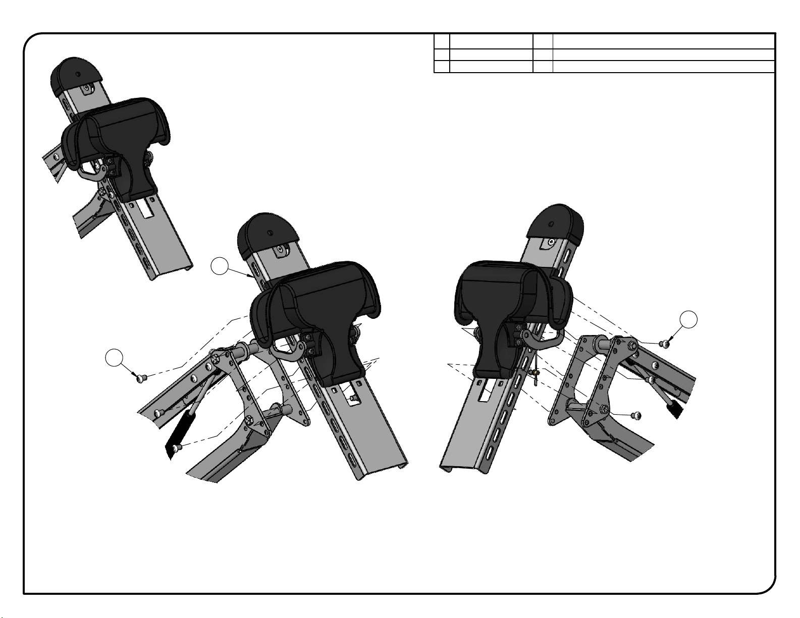
SP-HDA11-00
1
Floor Installation Kit
SP-HDA11
ADAPT SOLUTIONS
|[email protected]|866.641.0419|418.889.9838 fax
PART NUMBER
Honda Odyssey Speedy-Lift 2
DESCRIPTION
SPEEDY-LIFT 2 HONDA ODYSSEY 2011+
3
8
4 2
1
3
5
7
6
SCALE 1:4
SCALE 1:5
2 of 5
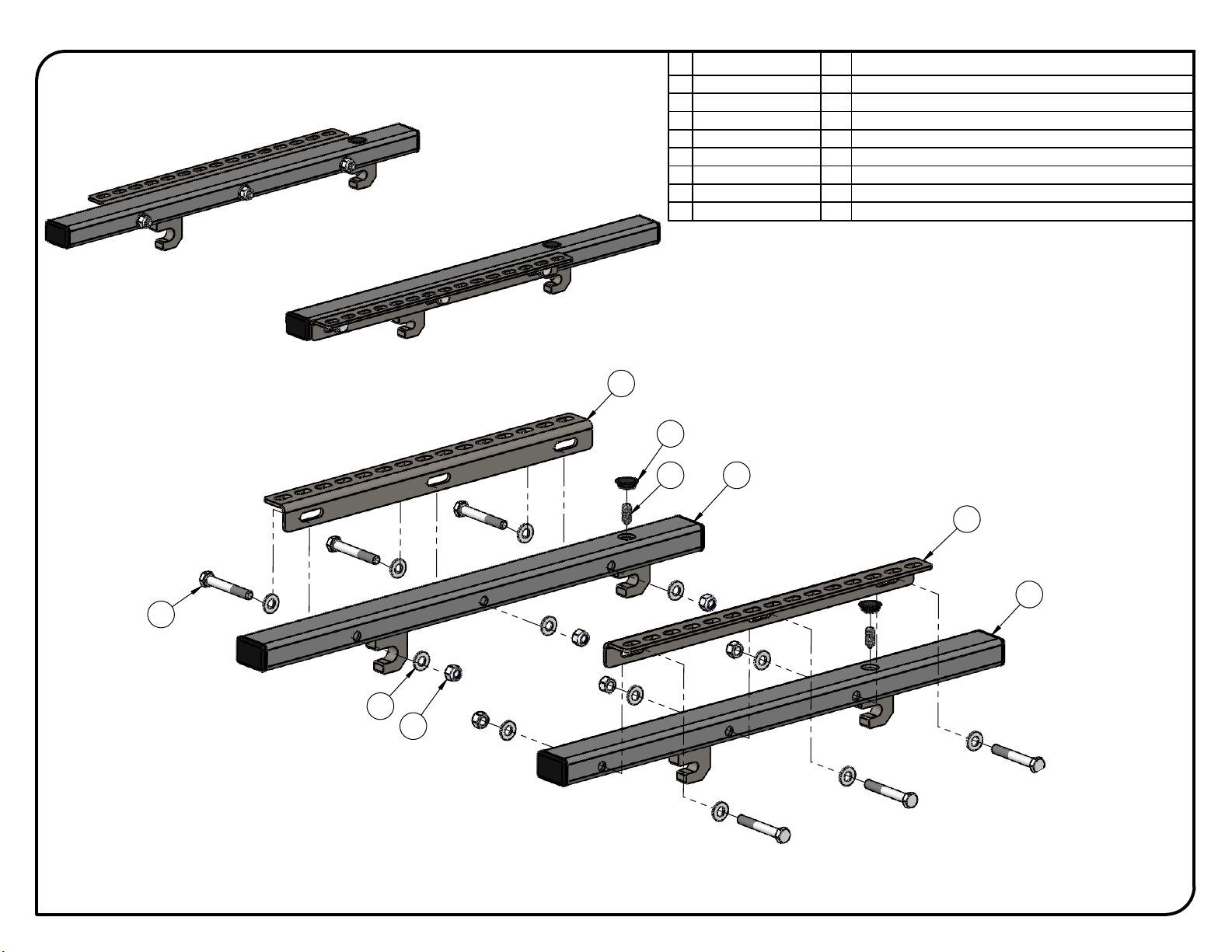
ITEM
PART NUMBER
QTY
DESCRIPTION
1
SL-HDA11-01
1
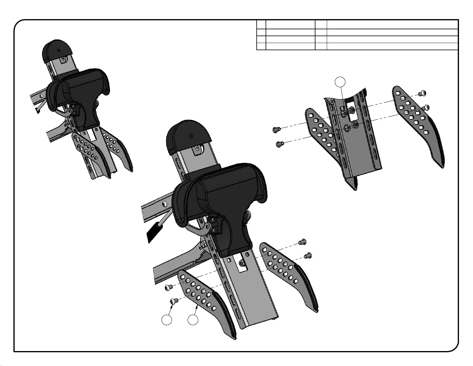
Floor Adaptor Honda Odyssey 2011 - Up -Left-
2
SL-HDA11-02
1
Floor Adapter for Honda Odyssey 2011 -Up -Right-
3
SL-EQRS145
2
Adaptor for the SPEEDY-LIFT rail on the floor adaptors
4
PRD 149-554P
2
Socket set screw cone point zinc plated 5/16-18 x 3/4
5
PRD 302-147P
6
Hex Cap Bolt Zinc Plated 5/16-18 x 2 1/4 G5
6
PRD 333-107
6
Nylon Insert Locknut 5/16-18
7
PRD 341-146P
12
Flat Washer Zinc Plated I.D. 11/32 SAE 5/16
8
AP S5-8A
2
Sheet metal plug - flush Ø0.625" Black
SP-HDA11
ADAPT SOLUTIONS
|[email protected]|866.641.0419|418.889.9838 fax
PART NUMBER
Honda Odyssey Speedy-Lift 2
DESCRIPTION
SPEEDY-LIFT 2 HONDA ODYSSEY 2011+
SCALE 1:5
7
10
6
7
9
8
4
5
1
2
3
SCALE 1:9
3 of 5
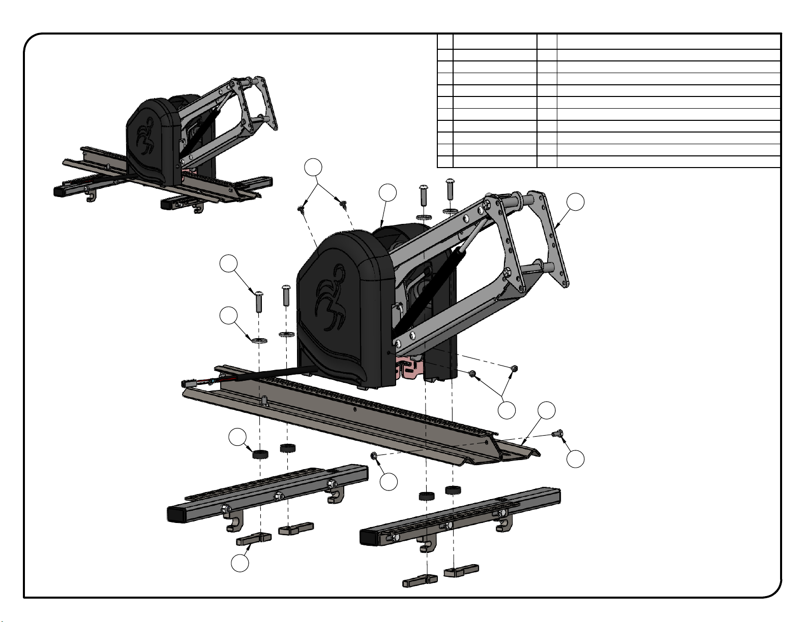
ITEM
PART NUMBER
QTY
DESCRIPTION
1
SP000
1
Mechanism Assembvly
2
SP100-01
1
Rail Assembly
3
SP600B
1
Housing Cover Assembly -Black-
4
SL-UNI-07
4
Nut for SPEEDY-LIFT rail
5
SL-UNI-08
4
Rail Spacer
6
SL-UNI-09
4
Rail Spacer Washer
7
PRD 110-104
4
Round washer head tapping screw #8 x 1/2
8
PRD 302-100P
1
Hex Cap Bolt Zinc Plated 1/4-20 x 1/2 G5
9
PRD 333-105M
1
Nylon Insert Locknut 1/4-20 Thin
10
PRD BSHCS51618114P
4
Button Head Socket Cap Screw Zinc Plated 5/16-18 x 1 1/4
SP-HDA11
ADAPT SOLUTIONS
|[email protected]|866.641.0419|418.889.9838 fax
PART NUMBER
Honda Odyssey Speedy-Lift 2
DESCRIPTION
SPEEDY-LIFT 2 HONDA ODYSSEY 2011+
2
1
SCALE 1:6
SCALE 1:5
2
4 of 5
ITEM
PART NUMBER
QTY
DESCRIPTION
1
SP700B
1
Hook Assembly -Black-
2
PRD 337-211P
6
Button Head Socket Cap Screw Zinc Plated 5/16-18 x 1/2
SP-HDA11
ADAPT SOLUTIONS
|[email protected]|866.641.0419|418.889.9838 fax
PART NUMBER
Honda Odyssey Speedy-Lift 2
DESCRIPTION
SPEEDY-LIFT 2 HONDA ODYSSEY 2011+
SCALE 1:4
2 1
SCALE 1:6
SCALE 1:4
3
5 of 5
ITEM
PART NUMBER
QTY
DESCRIPTION
1
SP740
2
Wheelchair support
2
PRD 337-211P
4
Button Head Socket Cap Screw Zinc Plated 5/16-18 x 1/2
3
PRD 2946
4
Flange Locknut Zinc Plated 5/16-18
SP-HDA11
ADAPT SOLUTIONS
|[email protected]|866.641.0419|418.889.9838 fax
PART NUMBER
Honda Odyssey Speedy-Lift 2
DESCRIPTION
SPEEDY-LIFT 2 HONDA ODYSSEY 2011+
1. Start by removing or stowing the seat in the position you want to install the SPEEDY-
LIFT.
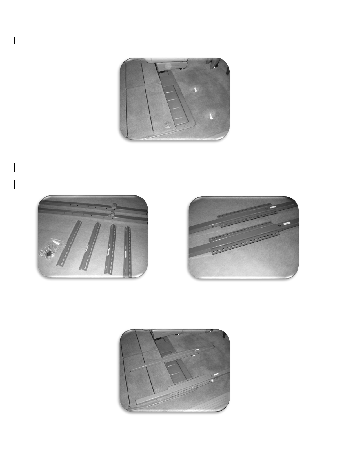
2. Pre-assemble the floor adaptor kit. Secure the slotted angle adaptors SL-EQRS145 to the floor adaptors
(tubing) using 5/16” X 2 1/4” bolts. NOTE: DO NOT FULLY TIGHTEN THE BOLTS.
3. Install the assembled adaptors in the vehicle. Place the adaptor over the “dog bones” and slide the
adaptor towards the front of the vehicle.
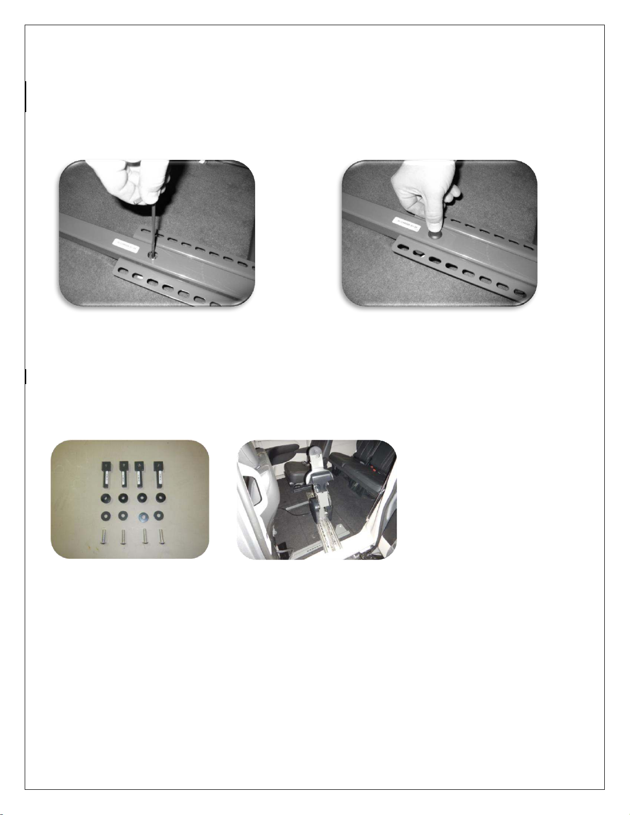
4. Secure the adaptors in place using a 5/16” X 3/4” socket set screw. Cover the socket set screw hole with
the provided cap plug. NOTE: IN SOME APPLICATIONS, THE ADAPTORS WILL SEEM LOOSE AND BE ABLE
TO MOVE FROM SIDE TO SIDE. THIS IS NORMAL AT THIS STAGE OF THE INSTALLATION.
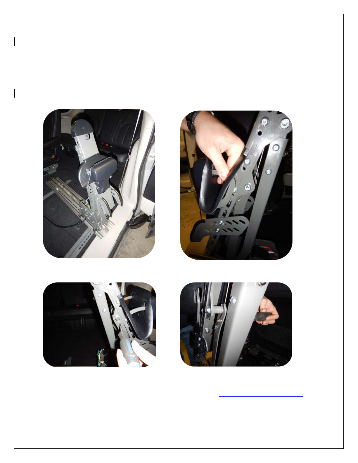
5. Place the SPEEDY-LIFT in the vehicle on the floor adaptors using the plastic shims between the
SPEEDY-LIFT and the floor adapters. Center the SPEEDY-LIFT in the door opening. Place the
SPEEDY-LIFT as close as possible to the door.

6. The SPEEDY-LIFT up/down and in/out motors can be disengaged manually to slide the SPEEDY-
LIFT in and out and move the arm up and down. NOTE: When disengaing the arm, it will spring up as the
arm of the SPEEDY-LIFT is aided by a 100-lb gas shock, so, hold the arm firmly when disengaging. To
disengage, move the handle to the right and push down. This will disengage the two motors and the arm
will spring up. To reengage, lift up the lever. You may have to move the arm and the unit back and forth.
7. Place the washer over the SPEEDY-LIFT track and use the 5/16” X 1 1/4” button head bolts to line
up the washer plate, the SPEEDY-LIFT track and the black plastic shim. Secure the SPEEDY-
LIFT to the floor adaptors using the threaded blocks SL-UNI-07.

8. Install the electrical wiring for the SPEEDY-LIFT. Follow the instructions found in the attached
document entitled: ELECTRICAL INSTALLATION FOR SPEEDY-LIFT.
9. Power the SPEEDY-LIFT all the way out. Attach the wheelchair hook and support assembly SP700 to
the head of the SPEEDY-LIFT. The height of the hook assembly may be adjusted depending on the
height or style of the wheelchair. Remove the plastic housing covers.
10. The stop up and stop down height may be adjusted using the bolts in the slotted holes on the up down
gear. NOTE: The stop up bolt is pre-adjusted for maximum travel.
STOP UP
STOP DOWN
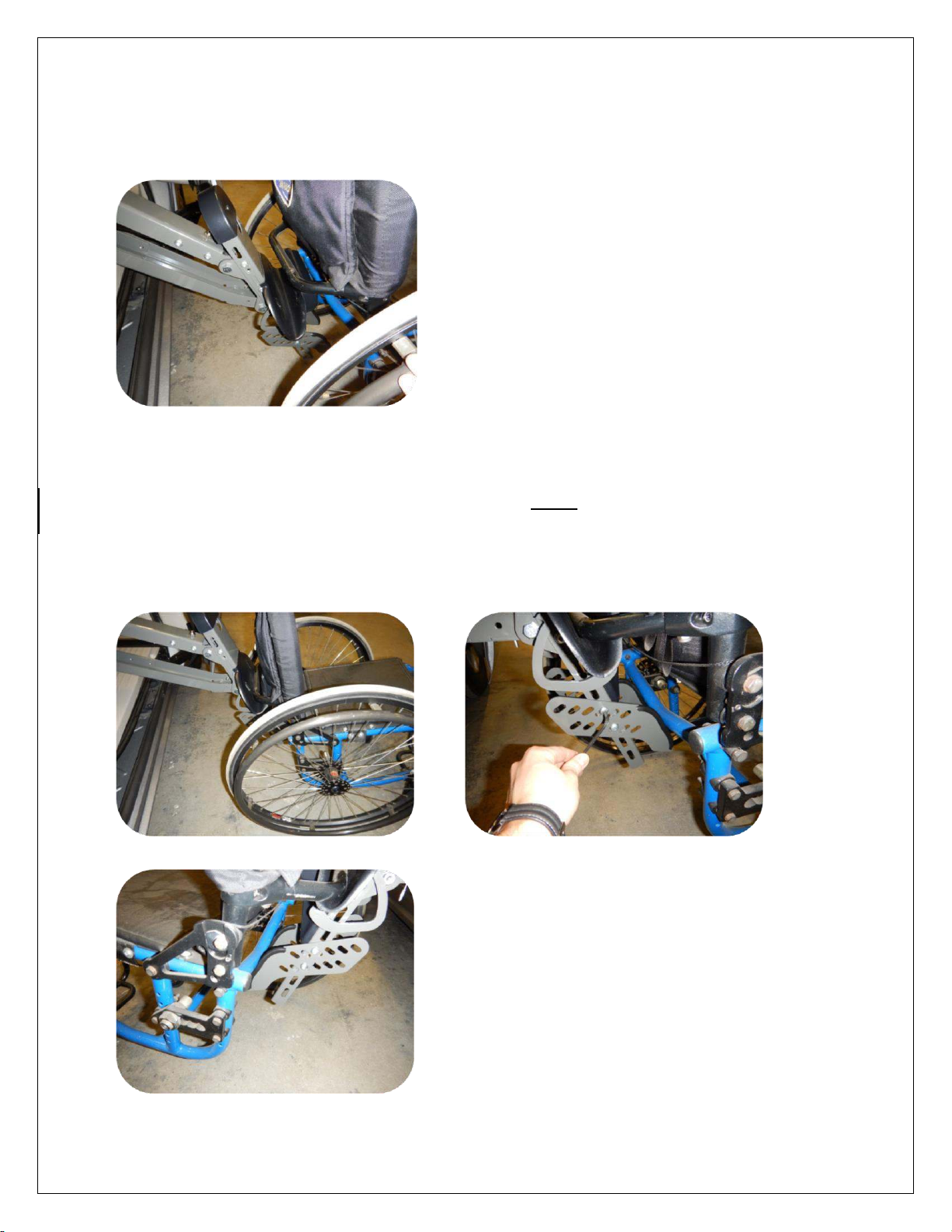
11. Press the ‘OUT’ button on the hand held pendant until the upper wheelchair support bracket is
positioned 1/4” to 1/2” below the rigidizer bar on the wheelchair. Adjust the stop down bolt so that the
arm stops in this position.
12. To properly position the lower support arms, back the wheelchair up over the upper wheelchair support
bracket. Press and hold the ‘IN’ button until the wheelchair barely starts to lift off the ground. Then adjust
the lower support arms to the wheelchair. Adjust the lifting angle of the wheelchair by sliding the lower
supports forward or back.
13. Adjust the locking mechanism. Remove the wheelchair from the SPEEDY-LIFT. Press and hold the
‘IN’ button until the SPEEDY-LIFT is in its full up position. While holding the lock closed, pull the
cable tight and secure the cable lock. Cut off the excess lenght of cable. Test slowly to see if the locking
mechanism operates properly.
NOTE: The SPEEDY-LIFT must be in the full up position. Proper adjustment will ensure that the
locking mecanism and cable will not fail. If the cable is adjusted with the SPEEDY-LIFT not in the full
up position, the cable will fail and the locking mecanism will no longer work.
FOR TECHNICAL SUPPORT CALL 866-641-0419 OR E-MAIL US TECH@ADAPTSOLUTIONS.COM
PLEASE HAVE THE SERIAL NUMBER OF THE UNIT ON HAND BEFORE PLACING YOUR CALL.

WARNING DECALS
After completing the installation of the SPEEDY LIFT, please take time to install the
warning decals. NOTE: The surface must be clean, dry and at ambient temperature for
the sticker to stick to the surface.
Start by locating a position to install the decals.
Clean the surface with the provided alcohol swab.
Peel off the backing of the sticker and then stick it to the cleaned surface.

TROUBLESHOOTING
PROBLEM
POSSIBLE CAUSES
SPEEDY LIFT
will not run
Bad electrical connections. Check and clean corrosion from all
connections including the car’s battery cable connections.
Hand pendant wire problem. Check hand pendant wire to make sure
it is properly plugged. Check the wire for any cuts. If so, replace the
wire.
Burnt out switch. Replace pendant.
Bad connection. Check the electronic module under the seat. Make
sure that all the wires are properly connected.
Burnt out electronic module. Contact Adapt-Solutions for
replacement module.
Burnt out actuator. Replace actuator.
Power Loss. The SPEEDY LIFT motor is not getting adequate
electrical power because of a loose connection. Check the SPEEDY
LIFT connections for tightness and corrosion (especially the ground
connection).
A partially discharged battery in the vehicle. Check the car’s battery
by trying the car lights or checking the voltage with a voltmeter
(should read 13.2 volts). Clean the car battery posts and cable clamps
thoroughly (remove the battery clamps off the battery posts and clean
them with a wire brush designed for that purpose). Coat the
connection with anticorrosion spray once reassembled. An
automotive battery may be weak, having enough power to start the
car but not enough power for continuous use.
ELECTRICAL INSTALLATION FOR SPEEDY-LIFT
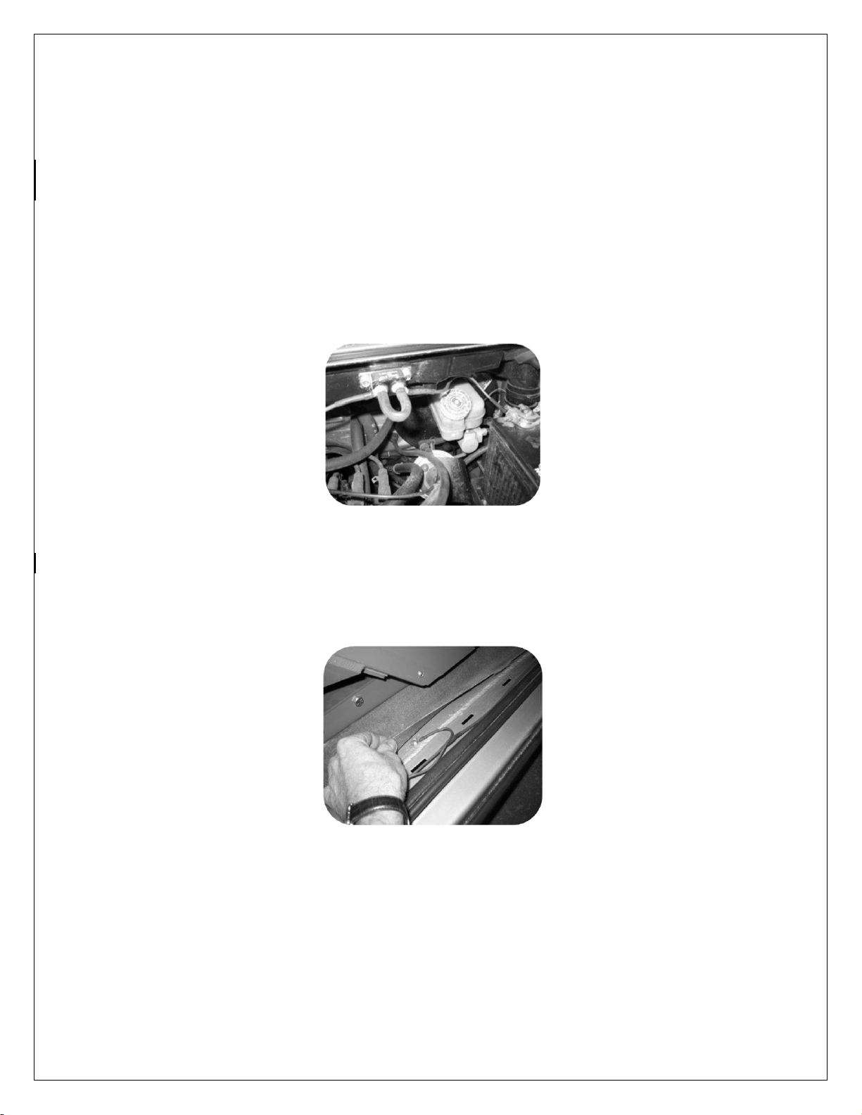
1. Thread the lead power cable (red +) under the doorstep molding and through the
firewall. WARNING: Pass through a grommet in the firewall to prevent the cable from
chaffing.
2. Install the circuit breaker near the battery and then connect the battery to the circuit
breaker.
3. Attach the ground wire (black -) to the vehicle’s frame, under the doorstep molding
using a self-tapping screw. NOTE: It is preferable to locate it in a spot where the sheet
metal is doubled-up to insure a better ground.
4. Thread the hand held control wire under the doorstep molding and up under the
dash. Secure the wire in place under the dash with a tie wrap and secure the hand
held control on the dash using “Velcro”. WARNING: Place the hand held control in a
safe place so that the door does not risk cutting off the wire.

ELECTRICAL BOX CONNECTIONS
ASENTO with SPEEDY-LIFT
SPEEDY LIFT ALONE
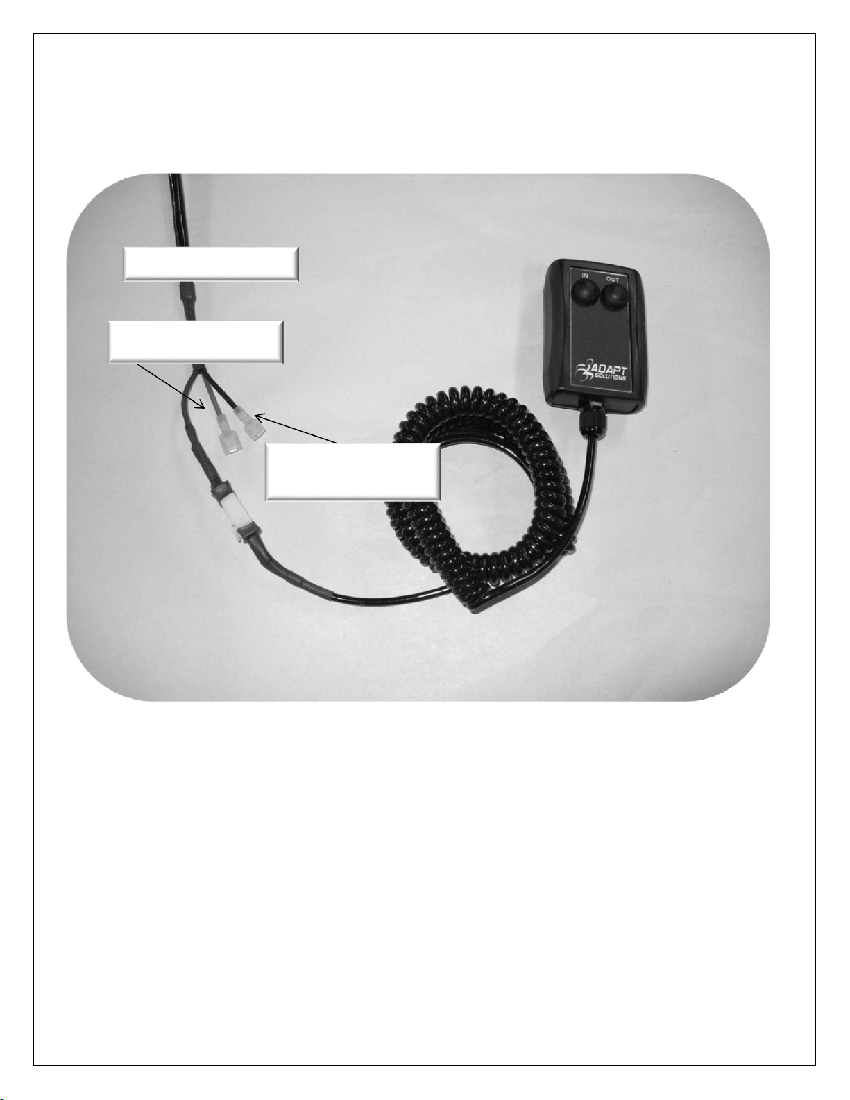
SPEEDY LIFT CORD
BLACK = GROUNDED TO
THE CHASSIS
RED = 12 V POWER
SUPPLY

ADAPT-SOLUTIONS #1 Ltd.
3 YEAR LIMITED WARRANTY
Adapt-Solutions # 1 Ltd. (Adapt Solutions), warrants to the original purchaser of an XL-BASE, XL-SEAT,
HI-LIFT, SPEEDY-LIFT, XL-BOARD, POWER-PULL or ASENTO that the equipment is free from
defects in material and workmanship for a period of three years from date of purchase.
During the first year of the warranty, Adapt Solutions will supply the replacement parts as well as a pre-set
monetary amount (determined by Adapt Solutions) for the repair if a defect in materiel or workmanship is
discovered. Labor claims must be approved by Adapt Solutions and an authorisation number (RMA) will
be given. Labor claims must be submitted within six (6) weeks of receiving the RMA to be processed. After
the initial year of this warranty, only parts and components are covered. This warranty does not cover
labor and other services after the initial year. Freight and other related repair charges will be the
responsibility of the original purchaser.
The only remedy for a defect in one of Adapt Solutions products shall be the repair or the replacement, at
the discretion of Adapt Solutions, of the defective part or component. If repair or replacement is not
commercially practical or cannot be timely made, Adapt Solutions may decide to refund the purchase
price of the equipment (XL-BASE; XL-SEAT; HI-LIFT; SPEEDY-LIFT; XL-BOARD; POWER- PULL;
ASENTO) instead of repairing or replacing the original equipment.
In no event shall Adapt Solutions be responsible for indirect, incidental or consequential damages, whether
such damages arise from claims based on contract, warranty, tort (including negligence), strict liability or
product liability.
All implied warranties, including any warranty of merchantability or fitness for a particular purpose, are
limited in their duration to the length of the warranty stated above for the affected component.
This warranty is to the original purchaser only, and excludes product damage due to installation error,
product misuse, product abuse, accidents, physical damage, damage in shipment, modifications not
made by Adapt Solutions, or repairs undertaken by anyone other than authorized distributors.
To obtain warranty parts or reimbursement, you must follow these procedures:
1. Obtain warranty authorization (RMA number) by calling your local Adapt Solutions dealer or Adapt
Solutions directly at 866-641-0419.
2. Return the faulty Adapt Solutions component/equipment, freight prepaid, to the address provided by
your Adapt Solutions dealer or Adapt Solutions with proof of purchase.
Adapt Solutions will pay for shipping back to the purchaser within the continental United States and
Canada if a defect in materiel or workmanship is discovered. Return freight and repair charges will be the
responsibility of the purchaser if the problem is not covered by warranty.
This warranty gives you specific legal rights, and you may also have other rights that vary from state to
state/ province to province. Adapt Solutions specifically does not authorize any person to extend the time
or scope of this warranty. For further information regarding this limited warranty, please contact us by
calling 1-866-641-0419 or by writing at the following address:
Adapt Solutions / Warranty Department
145 Damase-Breton
St-Lambert-de-Lauzon, Québec
G0S 2W0 Canada
Table of contents
Other SPEEDY-LIFT Automobile Accessories manuals


Popular Automobile Accessories manuals by other brands


CrimeStopper
CrimeStopper CS-9601PI Wiring diagram

Whelen Engineering Company
Whelen Engineering Company HELS Lighthead installation manual

Twinny Load
Twinny Load A 31 Fitting instructions

GROM Audio
GROM Audio VOL01 manual

Whispbar
Whispbar K447W Fitting Instructions for Basic Carrier

Leitner
Leitner ACS ROOF ROOF FOR ACS FORGED / CLASSIC manual


