Page 2
CAUTION! DO NOT LOOK DIRECTLY AT THESE LEDS WHILE THEY ARE ON.
MOMENTARY BLINDNESS AND/OR EYE DAMAGE COULD RESULT!
IMPORTANT WARNING!
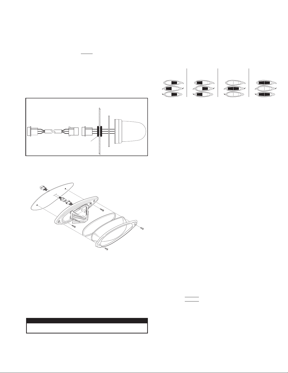
PHASE 1
LEFT
RIGHT
side lights up and
with side.alternates
PHASE 2
RIGHT
LEFT
side lights up and
with side.alternates
PHASE 3
BOTH sides flash together
(ON-OFF-ON).
PHASE 4
BOTH sides flash together
(OFF-ON-OFF).
Note: Phases 3 & 4 are visually indistinguishable.
then
then OFF
ON
ON
ON
OFF
OFF
then
then ON
OFF ON
OFF ON
OFF
then
then ON ON
OFF OFF
OFF OFF
then
then OFF
ON
ON
ON
ON
OFF
STROBE VERSION SHOWN
FOR REFERENCE ONLY
Mounting:
WARNING! Strobe light power supplies are high voltage devices. Do not
touch or remove the strobe tube assembly while in operation. Wait 10
minutes after disconnecting the power source before starting any work on
the power supply or system.
WARNING! All customer supplied wires that connect to the positive
terminal of the battery must be sized to supply at least 125% of the
maximum operating current and FUSED at the battery to carry that load.
DO NOT USE CIRCUIT BREAKERS WITH THIS PRODUCT!
Caution: Permanent mounting of this product will require drilling. It is
absolutely necessary to make sure that no other vehicle components
could be damaged by this process. Check both sides of the mounting
surface before starting. If damage is likely, select a different mounting
location.
1. Refer to the mounting dimensions shown on the exploded product view.
Mark off and drill two 1/4” mounting holes for two #10 x 1-1/4 sheet metal
screws into the mounting surface.
2. Drill a 1” wire hole and deburr the hole.
3. Feed the 15’ lighthead cable (included) through the wire hole and route it
towards your control head. Pass the lighthead connector through the
mounting gasket and the wire hole grommet (included) before connecting
the lighthead to the lighthead cable.
4. Connect the lighthead to the cable and install the grommet into the wire
hole. Secure the lighthead to the mounting surface using the two mounting
screws supplied.
5. Finish the installation by securing the gasket, lens and lens retainer with the
two lens screws.
6. Use the wiring diagram for the model being installed to complete the
electrical connections.
Scan-Lock™: To advance pattern: With the lighthead active, apply
+VBAT to the WHT/VIO wire for less than 1 second. To cycle to previous
patterns: Apply +VBAT for more than 1 second. To restore factory
default pattern: Turn off power to the lighthead. Apply +VBAT to the
WHT/VIO wire while turning the lighthead on. Continue to apply voltage to
the WHT/VIO wire for 5 seconds.
Mounting
Surface
Remember, the grommet must
be installed over the lighthead
connector before the grommet
is mounted onto the wire hole.
Grommet
Mounting
Gasket
SYNC Operation (LED models only): Some of the patterns available for
the standard SYNC lighthead are described as being either Phase 1
(PH.1) or Phase 2 (PH.2), Phase 3 (PH.3) or Phase 4 (PH.4). These terms
define how patterns on lightheads with their SYNC wires connected relate
to each other. Lightheads configured to display the same Phase of a given
pattern will flash simultaneously. Lightheads configured to Phase 1 of a
given pattern will alternate with Phase 2 lightheads. This concept is more
easily understood using the following illustration:
Split Lighthead Operation
1. SignalAlert™ 75................ PH.1
2. SignalAlert 75 ................... PH.2
3. SignalAlert 75 ................... PH.3
4. SignalAlert 75 ................... PH.4
5. CometFlash® 75............... PH.1
6. CometFlash 75 ................. PH.2
7. CometFlash 75 ................. PH.3
8. CometFlash 75 ................. PH.4
9. DoubleFlash 75 ............... PH.1
10. DoubleFlash 75 ............... PH.2
11. DoubleFlash 75 ............... PH.3
12. DoubleFlash 75 ............... PH.4
13. SingleFlash 75................. PH.1
14. SingleFlash 75................. PH.2
15. SingleFlash 75................. PH.3
16. SingleFlash 75................. PH.4
17. ComAlert™ 75 .................. PH.1
18. ComAlert 75...................... PH.2
19. ComAlert 75...................... PH.3
20. ComAlert 75...................... PH.4
21. LongBurst™ 75 ................. PH.1
22. LongBurst 75 .................... PH.2
23. LongBurst 75 .................... PH.3
24. LongBurst 75 .................... PH.4
25. PingPong™ 75 ................ PH.1
26. PingPong 75 .................... PH.2
27. PingPong 75 .................... PH.3
28. PingPong 75 .................... PH.4
29. SSNF 75 ........................... PH.1
30. SSNF 75 ........................... PH.2
31. SingleFlash 60.................. ALT
32. SingleFlash 60...................SIM
33. SingleFlash 90.................. ALT
34. SingleFlash 90...................SIM
35. SingleFlash 120................ ALT
36. SingleFlash 120.................SIM
37. SingleFlash 300 ..................ALT
38. SingleFlash 300 ..................SIM
39. DoubleFlash 150.................ALT
40. DoubleFlash 150.................SIM
41. ComAlert150.......................ALT
42. ComAlert150.......................SIM
43. ActionFlash™50 .................ALT
44. ActionFlash50 .....................SIM
45. ActionFlash150 ...................ALT
46. ActionFlash150 ...................SIM
47. ModuFlash™ ......................ALT
48. ModuFlash ..........................SIM
49. DoubleFlash 120 .............. ALT
50. DoubleFlash 120 ...............SIM
51. PingPong™ 120 ............... ALT
52. PingPong 120 ....................SIM
53. TripleFlash™ 75 ............... ALT
54. TripleFlash 75....................SIM
55. TripleFlash 120................. ALT
56. TripleFlash 120..................SIM
57. SigAlert Cal.™.................. ALT
58. SigAlert Cal. ......................SIM
59. Action 1............................. ALT
60. Action 1..............................SIM
61. Action 2............................. ALT
62. Action 2..............................SIM
63. CalScan™ .................. ALT/SIM
64. ActionScan™ .............. ALT/SIM
65. SteadyFlash 60
66. SteadyFlash 75
67. SteadyFlash 90
68. SteadyFlash 120
69. Steady & Steady
NOTE: BOLD = California Title XIII Compliant Pattern Italic = SYNC Patterns
NOTE: PHASE 1 ALWAYS ALTERNATES WITH PHASE 2
PHASE 3 ALWAYS ALTERNATES WITH PHASE 4
NOTE: The SYNC wire can be connected to other SYNC-capable power
supplies to synchronize their output.
Be sure to cap the SYNC wire if it is not used.
IMPORTANT! Before returning the vehicle to active service, visually
confirm the proper operation of this product, as well as all vehicle
components/equipment.
Flash Patterns


