SPENCE D50A User manual

www.SpenceValve.com
▲ WARNING
Failure to follow these instructions or
to properly install and maintain this
equipment could result in an explosion,
fire and/or chemical contamination
causing property damage and personal
injury or death.
Emerson Pressure Regulator must
be installed, operated and maintained
in accordance with federal, state and
local codes, rules and regulations
and Emerson Process Management
Regulator Technologies, Inc.
(Emerson) instructions.
If the regulator vents gas or a leak
develops in the system, service to
the unit may be required. Failure
to correct trouble could result in a
hazardous condition.
Installation, operation and maintenance
procedures performed by unqualied
personnel may result in improper
adjustment and unsafe operation. Either
condition may result in equipment
damage or personal injury. Only a
qualied person shall install or service
the Type D50A pressure regulator.
Introduction
Scope of the Manual
This manual provides instructions for the installation,
maintenance and parts ordering for Type D50A
pressure regulator.
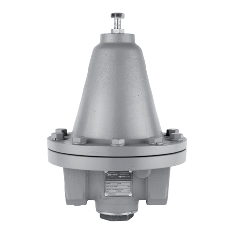
Spence Type D50A Pressure Regulator
Figure 1. Type D50A Pressure Regulator
Product Description
The Type D50A pressure reducing regulator
automatically reduces a high inlet pressure to a lower
delivery pressure and maintains the lower pressure
within reasonably close limits regardless of the
pressure uctuations on the inlet side of the regulator.
Instruction Manual
VCIMD-16107 Type D50A
August 2022

Specifications
The specifications section on this page provide the ratings and other specifications for the Type D50A.
1. The pressure/temperature limits in this Instruction Manual and any applicable standard or code limitation should not be exceeded.
Body Sizes and End Connection
1/4, 3/8, 1/2, 3/4, 1, 1 1/4, 1 1/2 and 2 NPTF
Maximum Inlet Pressure(1)
Air or water: 200 psi / 13.8 bar
Steam: 150 psi / 10.3 bar
Maximum Outlet Pressure(1)
Air or water: 150 psi / 10.3 bar
Steam: 125 psi / 8.62 bar
Maximum Operating Temperature(1)
Air or water: 180°F / 82°C
Steam: 400°F / 204°C
Outlet Pressure Range(1)
See Table 1
Materials of Construction
Body: Iron
Spring: Steel
Bottom Plug: Brass
Seat Disk
Air or Water: Nitrile (NBR)
Steam: Polytetrafluoroethylene (PTFE)
Diaphragm
Air or Water: Nitrile (NBR)
Steam: Bronze
BODY SIZE, NPT
SPRING RANGE
Air or Water Steam
psig
bar
psig
bar
1/4
2 to 25
0.14 to 1.72
2 to 25
0.14 to 1.72
20 to 60
1.38 to 4.14
20 to 60
1.38 to 4.14
30 to 100
2.07 to 6.90
30 to 100
2.07 to 6.90
50 to 150
3.45 to 10.3
50 to 125
3.45 to 8.62
3/8
2 to 30
0.14 to 2.07
2 to 30
0.14 to 2.07
20 to 70
1.38 to 4.83
20 to 70
1.38 to 4.83
40 to 110
2.76 to 7.58
40 to 110
2.76 to 7.58
90 to 150
6.21 to 10.3
90 to 125
6.21 to 8.62
1/2
2 to 30
0.14 to 2.07
2 to 30
0.14 to 2.07
10 to 50
0.69 to 3.45
10 to 50
0.69 to 3.45
30 to 125
2.07 to 8.62
30 to 125
2.07 to 8.62
50 to 150
3.45 to 10.3
50 to 125
3.45 to 8.62
3/4
2 to 20
0.14 to 1.38
2 to 20
0.14 to 1.38
10 to 35
0.69 to 2.41
10 to 35
0.69 to 2.41
30 to 75
2.07 to 5.17
30 to 75
2.07 to 5.17
50 to 110
3.45 to 7.58
50 to 110
3.45 to 7.58
105 to 150
7.24 to 10.3
105 to 125
7.24 to 8.62
1
2 to 20
0.14 to 1.38
2 to 20
0.14 to 1.38
10 to 45
0.69 to 3.10
10 to 45
0.69 to 3.10
20 to 60
1.38 to 4.14
20 to 60
1.38 to 4.14
55 to 100
3.79 to 6.90
55 to 100
3.79 to 6.90
90 to 150
6.21 to 10.3
90 to 125
6.21 to 8.62
1-1/4 and 1-1/2
2 to 15
0.14 to 1.03
2 to 15
0.14 to 1.03
10 to 30
0.69 to 2.07
10 to 30
0.69 to 2.07
20 to 50
1.38 to 3.45
20 to 50
1.38 to 3.45
45 to 100
3.10 to 6.90
45 to 100
3.10 to 6.90
90 to 150
6.21 to 10.3
90 to 125
6.21 to 8.62
2
2 to 20
0.14 to 1.38
2 to 20
0.14 to 1.38
10 to 60
1.69 to 4.14
10 to 60
1.69 to 4.14
20 to 100
1.38 to 6.90
20 to 100
1.38 to 6.90
90 to 150
6.21 to 10.3
90 to 125
6.21 to 8.62
Table 1. Outlet Pressure Range
2
Type D50A

Air and Water Service
Type D50A regulators are available in 1/4 to 2 NPT
sizes with iron bodies and feature a variety of
optional internal trim (diaphragm, piston and cylinder)
that enable them to be used in a wide range
of applications.
Each regulator is equipped with a pressure spring
selected to provide the desired outlet or reduced
delivery pressure setting. Depending on the adjusting
spring installed, delivery pressures may be adjusted
from a minimum of 2 psig / 0.14 barg to a maximum
of 150 psig / 10.3 barg. The range of adjustment or
satisfactory working range of the individual springs
that may be tted to each regulator size is listed in the
spring range table. See Table 2.
The regulator is designed for systems with a maximum
operating temperature of 400°F / 204°C. In addition
to the standard specications indicated in Table 1,
any combination of body material, piston cylinder and
diaphragm is available to special order.
The Type D50A air and water regulators are suitable
for a variety of applications including paint spray
equipment, dishwashers, air tanks and equipment,
food, chemical and industrial process gases and many
other applications.
Steam Service
These regulators are designed for steam operating
temperatures up to 400°F / 204°C and are available
in 1/4 to 2 NPT sizes with iron bodies. Iron body
regulators have a PTFE seat and are for systems with
initial pressures up to 250 psig / 17.2 barg.
Regulators will normally be equipped as indicated
in the table but other combinations of body material,
piston-cylinder and diaphragm are available to
special order.
The Type D50A Steam Pressure Reducing and
Regulating Regulator is ideally suited for installation in
pressing irons, steam cookers, degreasers, sterilizers,
vulcanizers and hundreds of other applications.
Type D50A Steam Regulators can also be furnished
with a dierential pressure control feature which may
be desirable in steam/oil atomizing service.
Figure 2. Type D50A Schematic Figure 3. Type D50A Adjusting Screw Options
AIR OR WATER SERVICE
STEAM SERVICE
STANDARD
ADJUSTING SCREW
T-HANDLE
3
Type D50A

Optional Differential Pressure Control
The Type D50A Steam Regulator can be factory
modied to serve as a constant dierential pressure
control regulator by incorporating a 1/4 NPT side tap in
the spring housing.
In a typical steam-oil atomizing installation, uid
loading pressure is introduced above the diaphragm
of the regulator and steam is delivered through the
regulator at a regulated pressure higher than the
loading pressure, with the dierence in pressure being
determined by the diaphragm spring setting. The outlet
steam pressure is maintained automatically to provide
a constant, xed pressure dierential between the
steam pressure and the oil pressure. Variations in the
loading pressure are reected in a pound-for-pound
change in the discharge pressure.
Regulators equipped with the optional dierential
pressure control are tted with a pressure-tight closing
cap and gasket over the pressure adjusting screw and
a gasket above the diaphragm to ensure a good seal
between the spring housing and the regulator body.
Principle of Operation
When the fluid supply is cut in, the regulator is in wide
open position. Fluid flowing to the system creates a
rising delivery pressure which feeds back through the
control ports to the underside of diaphragm. As the
pressure on diaphragm approaches a balance with the
force exerted by adjusting spring, disk is throttled to a
position where just enough water flows to maintain the
set delivery pressure.
Installation
▲ WARNING
Personal injury or system damage
may result if this pressure regulator
is installed, without appropriate
overpressure protection, where service
conditions could exceed the limits given
in the Specifications section and/or
pressure regulator nameplate.
Additionally, physical damage to
the pressure regulator may result in
personal injury or property damage due
to escaping of accumulated gas. To
avoid such injury and damage, install
the pressure regulator in a safe location.
All pressure equipment should be
installed in a non-seismic area;
should not be exposed to fire; and
should be protected from thunderbolt
(lightning) strikes.
1. Install a strainer upstream of the Type D50A.
The built-in strainer screen is secondary
protection only.
2. Install Type D50A regulator in a horizontal position
with the spring chamber upright. For other
installation requirements, consult the factory.
3. Before installing the regulator, thoroughly flush
out the piping and the regulator to remove any
foreign material.
4. Install the regulator with the inlet pipe fitted to
the inlet connection identified on the regulator
body. Use a good pipe joint compound on the
male pipe threads and do not over tighten the
regulator connections.
Adjusting the Delivery Pressure
1. Loosen the adjusting screw lock nut (key 3).
2. Adjust the regulator’s delivery pressure setting
by turning the adjusting screw (key 2) or
optional T-handle (key 1) at the top of the spring
chamber (key 5).
3. To increase the delivery pressure, turn the
adjusting screw clockwise (into the spring
chamber). To decrease the delivery pressure, turn
the adjusting screw counter-clockwise (out of the
spring chamber).
4. Tighten the adjusting screw lock nut after the
adjustment has been made.
5. Draw flow through the regulator and shutoff, after
adjustment, to check for proper set pressure.
Table 2. Type D50A Torque Values
VALVE SIZE, NPT TORQUE VALUE
1/4 100
3/8 150
1/2 200
3/4 200
1 250
1-1/4 350
1-1/2 350
2 350
4
Type D50A

Maintenance
▲ WARNING
To avoid personal injury, property
damage or equipment damage caused
by sudden release of pressure or
explosion of accumulated gas, do
not attempt any maintenance or
disassembly without first isolating
the pressure regulator from system
pressure and relieving all internal
pressure from the pressure regulator.
Pressure regulator that have been
disassembled for repair must be
tested for proper operation before
being returned to service. Only
parts manufactured by Emerson
should be used for repairing this
pressure regulator.
Due to normal wear or damage that
may occur from external sources, this
pressure regulator should be inspected
and maintained periodically. The
frequency of inspection and replacement
of parts depends upon the severity of
service conditions or the requirement
of local, state and federal rules
and regulations.
△ CAUTION
Before attempting to replace any spare
parts, be sure to shut off all pressure
connections to the regulator. With
the regulator closed however, system
pressure could still be locked between
the shutoff valve and the inlet and/
or outlet sides of the regulator. Before
proceeding with any regulator service,
be certain to relieve the pressure from
both sides of the regulator.
For ease of operation and maintenance, install the
manual shutoff valves upstream and downstream from
the regulator.
Servicing Diaphragm(s) and
Pressure Spring
1. Loosen the lock nut and turn the adjusting screw
counterclockwise until the pressure spring is
no longer under tension. When reassembling,
run the adjusting screw down until the lock
nut almost touches the spring chamber. This
will give you approximately the same set as
before disassembly.
2. Remove the assembly screws securing the spring
chamber to the body. During reassembly, tighten
the screws evenly in a star pattern. See Chart
below for torque values.
3. Remove the spring chamber. Then remove the
spring button, pressure spring and pressure plate.
4. Remove the diaphragm(s) and diaphragm gasket
(a diaphragm gasket is only present when
construction calls for metal diaphragms).
5. Remove the pusher post button. During
reassembly, ensure the pusher post button is
centered properly on the pusher post.
6. Inspect all parts for wear and damage and
replace if necessary. Reassemble parts in reverse
order. Do not overtighten. Follow the Operation
Instructions to reset the delivery pressure.
Servicing the Cylinder, Piston, Strainer
Screen and Plug Gasket
1. Loosen the lock nut and turn the adjusting screw
counterclockwise until the pressure spring is
no longer under tension. When reassembling,
run the adjusting screw down until the lock
nut almost touches the spring chamber. This
will give you approximately the same set as
before disassembly.
2. Remove the bottom plug. Take care, as the bottom
plug is under slight tension as a result of the piston
spring acting against the bottom plug. Remove the
piston, piston spring and strainer screen.
3. Thoroughly clean the strainer screen and remove
any debris from the valve body.
4. Remove the hexagon cylinder.
5. Inspect all parts for wear and damage. If either the
cylinder or piston need replacing, it is necessary to
replace both as both parts wear equally.
6. Reassemble the valve in reverse order. Do not
overtighten. Follow the Operation Instructions to
reset the delivery pressure.
5
Type D50A

Parts List
Key Description Part Number
1 Adjusting screw
Standard
1/4 NPT GT11312106
3/8, 1/2 and 3/4 NPT GT11312097
1 and 1-1/4 NPT GT11312094
1-1/2 NPT GT11312095
2 NPT GT11312354
T-Handle
1/4 NPT GT11424490
3/8, 1/2 and 3/4 NPT GT11318293
1, 1-1/4 and 1-1/2 NPT GT11318307
2 Lock nut
1/4 NPT GT11312107
3/8, 1/2 and 3/4 NPT GT11312099
1, 1-1/4 and 1-1/2 NPT GT11312104
2 NPT (Standard) GT11312105
3 Nameplate - - - - - - - - - - -
4 Spring Chamber, Iron
1/4 NPT GT11516430
3/8 NPT GT11516431
1/2 NPT GT11516432
3/4 NPT GT11516434
1 NPT GT11516437
1-1/4 and 1-1/2 NPT GT11516439
2 NPT GT11516440
5 Spring Button
1/4 NPT GT11312572
3/8, 1/2, 3/4, 1, 1-1/4 and 1-1/2 NPT GT11312187
2 NPT GT11318131
6 Spring, Steel See Table 3
7 Pressure Plate
1/4 NPT GT11312588
3/8 NPT GT11314448
1/2 NPT GT11312454
3/4 NPT GT11312994
1, 1-1/4 and 1-1/2 NPT GT11312455
2 NPT GT11314447
8 Diaphragm
Air or Water, Nitrile (NBR)
1/4 NPT GT11312394
3/8 NPT GT11312404
1/2 NPT GT11312379
3/4 NPT GT11312382
1 NPT GT11312408
1-1/4 and 1-1/2 NPT GT11312413
2 NPT GT11312417
Steam, Bronze
1/4 NPT (3 required) GT11312392
3/8 NPT (3 required) GT11312406
1/2 NPT (3 required) GT11312383
3/4 NPT (3 required) GT11312385
1 NPT (4 required) GT11312411
1-1/4 and 1-1/2 NPT (4 required) GT11312415
2 NPT (4 required) GT11312534
Parts Ordering
When corresponding with your local Sales Oce
about this equipment, always reference the equipment
regulator size, service and serial number.
When ordering replacement parts, reference the key
number of each needed part as found in the following
parts list and indicate the part number.
9 Diaphragm Gasket (For Steam only)
1/4 NPT GT11312393
3/8 NPT GT11312407
1/2 NPT GT11312384
3/4 NPT GT11312386
1 NPT GT11312412
1-1/4 and 1-1/2 NPT GT11312416
2 NPT GT11312535
10 Screw (6 required)
1/4 NPT GT11312276
3/8 NPT GT11312088
1/2 and 3/4 NPT GT11312102
1 NPT GT11312089
1-1/4 and 1-1/2 NPT GT11312093
2 NPT GT11312090
11 Nut (6 required) (not shown)
1/4 NPT GT11312280
3/8 NPT GT11312086
1/2, 3/4 and 1 NPT GT11312103
1-1/4 and 1-1/2 NPT GT11312091
2 NPT GT11312092
12 Pusher Post Button
1/4 NPT GT11312258
3/8 NPT GT11312405
1/2 and 3/4 NPT GT11312366
1 NPT GT11312442
1-1/4 and 1-1/2 NPT GT11310766
2 NPT GT11310026
13 Screen
1/4 and 3/8 NPT GT11312395
1/2 and 3/4 NPT GT11312380
1 NPT GT11312488
1-1/4 and 1-1/2 NPT GT11312489
2 NPT GT11312525
14 Cylinder
1/4 NPT GT11312559
3/8 NPT
Air or Water GT11312560
Steam GT11312559
1/2 and 3/4 NPT GT11312443
1 NPT GT11313032
1-1/4 and 1-1/2 NPT GT11317832
2 NPT GT11327029
15 Piston Assembly
Air or Water, Nitrile (NBR)
1/4 NPT GT11312587
3/8 NPT GT11312708
1/2 and 3/4 NPT GT11318275
1 NPT GT11310769
1-1/4 and 1-1/2 NPT GT11325019
2 NPT GT11312709
Steam, Bronze
1/4 NPT GT11320549
3/8 NPT GT11320550
1/2 and 3/4 NPT GT11320196
1 NPT GT11319040
1-1/4 and 1-1/2 NPT GT11319042
2 NPT GT11319043
16 Piston Spring
1/4 and 3/8 NPT GT11312214
1/2, 3/4 and 1 NPT GT11312192
1-1/4 and 1-1/2 NPT GT11312414
2 NPT GT11310027
Key Description Part Number
6
Type D50A

17 Body, Iron
1/4 NPT GT11516421
3/8 NPT GT11516422
1/2 NPT GT11516423
3/4 NPT GT11516424
1 NPT GT11516425
1-1/4 NPT GT11516427
1-1/2 NPT GT11516428
2 NPT GT11516429
18 Bottom Plug Gasket
1/4 and 3/8 NPT GT11464918
1/2 and 3/4 NPT GT11464919
1, 1-1/4 and 1-1/2 NPT GT11313278
2 NPT GT11312348
BODY SIZE, NPT
SPRING RANGE
PART NUMBER
Air or Water Steam
psig
bar
psig
bar
1/4
2 to 25
0.14 to 1.72
2 to 25
0.14 to 1.72
GT11312401
20 to 60
1.38 to 4.14
20 to 60
1.38 to 4.14
GT11312402
30 to 100
2.07 to 6.90
30 to 100
2.07 to 6.90
GT11312537
50 to 150
3.45 to 10.3
50 to 125
3.45 to 8.62
GT11312583
3/8
2 to 30
0.14 to 2.07
2 to 30
0.14 to 2.07
GT11312188
20 to 70
1.38 to 4.83
20 to 70
1.38 to 4.83
GT11312189
40 to 110
2.76 to 7.58
40 to 110
2.76 to 7.58
GT11312190
90 to 150
6.21 to 10.3
90 to 125
6.21 to 8.62
GT11312191
1/2
2 to 30
0.14 to 2.07
2 to 30
0.14 to 2.07
GT11312189
10 to 50
0.69 to 3.45
10 to 50
0.69 to 3.45
GT11312190
30 to 125
2.07 to 8.62
30 to 125
2.07 to 8.62
GT11312191
50 to 150
3.45 to 10.3
50 to 125
3.45 to 8.62
GT11314453
3/4
2 to 20
0.14 to 1.38
2 to 20
0.14 to 1.38
GT11312189
10 to 35
0.69 to 2.41
10 to 35
0.69 to 2.41
GT11312190
30 to 75
2.07 to 5.17
30 to 75
2.07 to 5.17
GT11312191
50 to 110
3.45 to 7.58
50 to 110
3.45 to 7.58
GT11314453
105 to 150
7.24 to 10.3
105 to 125
7.24 to 8.62
GT11312196
1
2 to 20
0.14 to 1.38
2 to 20
0.14 to 1.38
GT11313528
10 to 45
0.69 to 3.10
10 to 45
0.69 to 3.10
GT11312221
20 to 60
1.38 to 4.14
20 to 60
1.38 to 4.14
GT11310547
55 to 100
3.79 to 6.90
55 to 100
3.79 to 6.90
GT11312257
90 to 150
6.21 to 10.3
90 to 125
6.21 to 8.62
GT11313564
1-1/4 and 1-1/2
2 to 15
0.14 to 1.03
2 to 15
0.14 to 1.03
GT11313528
10 to 30
0.69 to 2.07
10 to 30
0.69 to 2.07
GT11312221
20 to 50
1.38 to 3.45
20 to 50
1.38 to 3.45
GT11310547
45 to 100
3.10 to 6.90
45 to 100
3.10 to 6.90
GT11312257
90 to 150
6.21 to 10.3
90 to 125
6.21 to 8.62
GT11313564
2
2 to 20
0.14 to 1.38
2 to 20
0.14 to 1.38
GT11313529
10 to 60
1.69 to 4.14
10 to 60
1.69 to 4.14
GT11312744
20 to 100
1.38 to 6.90
20 to 100
1.38 to 6.90
GT11312238
90 to 150
6.21 to 10.3
90 to 125
6.21 to 8.62
GT11312538
19 Bottom Plug Assembly, Brass
1/4 and 3/8 NPT GT11318731
1/2 and 3/4 NPT GT11330000
1 NPT GT11318746
1-1/4 and 1-1/2 NPT GT11318744
2 NPT GT11469313
22 Screw (Bottom Plug) (6 required), For 2 NPT only GT11312113
Key Description Part Number Key Description Part Number
Table 3. Key 6, Spring Part Number
7
Type D50A

1
2
4
5
6
7
10
12
13
14
15
17
18
16
19
15C15B
15A
9
8
INLET
E
3
21
20
22 23
24
3
21
20
22 23
24
VCIMD-16107 © 2022 Emerson Electric Co. All rights reserved. 08/22.
The Emerson logo is a trademark and service mark of Emerson Electric Co.
All other marks are property of their prospective owners.
Spence is a mark owned by one of the companies in the Emerson Automation
Solutions business unit of Emerson Electric Co.
The contents of this publication are presented for informational purposes only,
and while every eort has been made to ensure their accuracy, they are not to
be construed as warranties or guarantees, express or implied, regarding the
products or services described herein or their use or applicability. All sales are
governed by our terms and conditions, which are available upon request. We
reserve the right to modify or improve the designs or specications of such
products at any time without notice.
Emerson Process Management Regulator Technologies, Inc does not
assume responsibility for the selection, use or maintenance of any product.
Responsibility for proper selection, use and maintenance of any Emerson
Process Management Regulator Technologies, Inc. product remains solely with
the purchaser.
VARIATION D-WITH PRESSURE SCREW CAP AND DIFFERENTIAL CONNECTION
ONLY FOR 2 NPT
Figure 4. Type D50A Pressure Regulator Assembly
Type D50A
Emerson Automation Solutions
Americas
McKinney, Texas 75070 USA
T +1 800 558 5853
+1 972 548 3574
Europe
Bologna 40013, Italy
T +39 051 419 0611
Asia Pacic
Singapore 128461, Singapore
T +65 6777 8211
Middle East and Africa
Dubai, United Arab Emirates
T +971 4 811 8100
SpenceValve.com
Table of contents
Other SPENCE Controllers manuals
Popular Controllers manuals by other brands
Johnson Controls
Johnson Controls TEC3010 installation instructions
Tecnoware
Tecnoware POWER REG 1 user manual

Speck pumps
Speck pumps Badu Eco Touch II Installation, operating and service manual

MICRO-AIR
MICRO-AIR EasyTouch Operation manual
Mylex
Mylex PCI to Ultra 160 SCSI RAID Controller AcceleRAID... installation guide
HydroPoint
HydroPoint WeatherTRAK Chassis 7 installation guide
