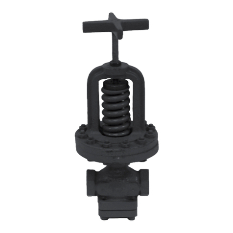
SPENCE D50 User manual

Instruction Manual
VCIMD-16110
www.SpenceValve.comwww.SpenceValve.com
Type D50 Pressure Regulator
▲ WARNING
Failure to follow these instructions or
to properly install and maintain this
equipment could result property damage
and personal injury or death.
Type D50 pressure regulator must be
installed, operated and maintained
in accordance with federal, state and
local codes, rules and regulations and
Emerson instructions.
If the valve vents gas or a leak develops
in the system, service to the unit may be
required. Failure to correct issue could
result in a hazardous condition.
Installation, operation and maintenance
procedures performed by unqualified
personnel may result in improper
adjustment and unsafe operation. Either
condition may result in equipment
damage or personal injury. Only a
qualified person shall install or service
the Type D50 pressure regulator.
Introduction
Scope of the Manual
This manual provides instructions for the installation,
troubleshooting, maintenance and parts ordering for
Type D50 pressure regulator.
Product Description
The Type D50 Pressure Regulator is a direct-operated
valve normally closed, single seat design featuring
packless construction, balanced metal, diaphragms
and protected main spring.
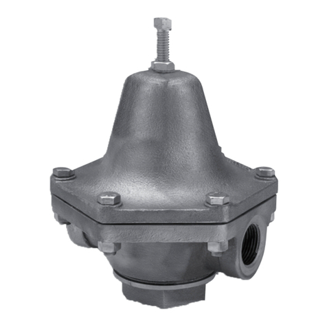
Figure 1. Types D50 Pressure Regulator
Type D50
April 2022

Specications
This section lists the specications for the Type D50 pressure regulator. Factory specications are stamped on the
nameplate fastened on the regulator at the factory.
Valve Temperature Rating(1)
Stainless steel Disk
Cast iron: 400°F / 204°C
Teflon®Disk
Cast iron: 300°F / 149°C
Main Valve Material
Cast iron
Approximate Weight
3.6 to 13.6 lbs / 8 to 30 kg
Valve Sizes
NPS 1/2, 3/4, 1, 1-1/4, 1-1/2 and 2 /
DN 15, 20, 25, 32, 40 and 50
End Connection Styles
NPT and BSPT
Valve Pressure Rating(1)
Stainless steel Disk
Cast iron: 200 psig / 13.8 bar
Teflon®Disk
Cast iron: 300 psig / 21.0 bar
1. The pressure/temperature limits in this Instruction Manual and any applicable standard or code limitation should not be exceeded.
Principle of Operation
The Type D50 is a direct-operated regulator.
Downstream pressure is registered through the control
ports to the under side of the diaphragm. As the
pressure on diaphragm approaches a balance with the
force exerted by the adjusting spring, disk is throttled
to a position where just enough uid ows to maintain
the set delivery pressure.
Intended Purpose
The Type D50 Direct Acting Pressure Regulator
is a compact, moderately priced steam, water or
gas regulator intended to satisfy most fundamental
requirements for pressure reduction.
Teon®is a mark owned by E.I. du Pont de Nemours and Co.
Installation
▲ WARNING
Personal injury or system damage
may result if this regulator is installed,
without appropriate overpressure
protection, where service conditions
could exceed the limits given in
the Specications section and/or
regulator nameplate.
Additionally, physical damage to the
regulator may result in personal injury
or property damage due to escaping of
accumulated gas. To avoid such injury
and damage, install the regulator in a
safe location.
Under enclosed conditions or indoors,
escaping gas may accumulate and be an
explosion hazard. In this case, the vent
should be piped outdoors.
For regulator constructions with a
spring case vent, the vent should be
kept open to permit free ow of gas
to the atmosphere. Protect openings
against entrance of rain, snow, insects
or any other foreign material that may
plug the spring case vent or vent line.
All pressure equipment should be
installed in a non-seismic area;
should not be exposed to re; and
should be protected from thunderbolt
(lightning) strikes.
2
Type D50

SPRING BUTTON
ADJUSTING SPRING
DIAPHRAGM(1)
DIAPHRAGM GASKET(1)
STEM BUSHING ASSEMBLY(1)
SEAT RING(1)
SEAT RING(2)
OPTIONAL TEFLON®
DISK FOR LIQUID
AND GAS SERVICE
TEFLON®DISK ASSEMBLY(2)
DISK(1)
BOTTOM PLUG GASKET(1)
The above parts are all that are available.
1. Parts contained in repair kit.
2. Parts substituted in Teon®repair kit.
Figure 2. Type D50 Operational Schematic
Teon®is a mark owned by E.I. du Pont de Nemours and Co.
3
Type D50

Planning the Installation
1. Locate the pressure regulator in a straight run of
horizontal pipe. See Figure 4.
2. Allow access room above and below the valve for
inspection and maintenance.
3. For steam service, in order to prevent
water hammer and erratic operation, install
properly sized traps to provide proper
drainage of condensate before and after the
pressure regulator.
4. Avoid the damaging effects of scale and dirt in
pipe lines by installing a Y-Type Strainer as shown
in Figure 4.
5. Provide a 3-valve by-pass to facilitate inspection
and maintenance without interrupting service.
6. If the pressure rating of the downstream piping
or connected equipment is less than the initial
pressure, install a safety valve as shown in
Figure 4.
7. Install initial and delivery pressure gauges to
indicate performance. When long runs of piping
Installing the Valve
1. Flush the piping system thoroughly to clear it of
any debris.
2. Mount the valve between unions with the arrows
under the diaphragm flange pointing in the
direction of the flow.
Figure 3. Aspirator Location Mark
NORMAL POSITION
ASPIRATOR LOCATION MARK
ADJUSTED POSITION
are involved, the delivery pressure gauge should
be located as close to the process or equipment
controlled as is practical.
8. To eliminate excessive noise and enhance stability
with steam and other compressible fluids:
a. Avoid single pressure reduction in excess of
5 to 1 ratio.
b. Enlarge the delivery pipe size to effect a
reasonable flow velocity at the reduced
pressure. A concentric tapered transition
is recommended.
c. Avoid sharp turns close to the regulator outlet
as well as bull-headed tee connections to low
pressure mains.
4
Type D50

D1 D2
Adjusting the Delivery Pressure
1. When received, the Type D50 Pressure Regulator
is preset to the delivery pressure listed on the
box label.
To change the delivery pressure:
a. Loosen the lock nut on the adjusting screw.
b. Turn adjusting screw clockwise to increase the
delivery pressure; (or)
c. Turn the adjusting screw counterclockwise to
decrease the delivery.
d. Retighten the lock nut.
2. Mount the valve between unions with the arrows
under the diaphragm flange pointing in the
direction of the flow.
Troubleshooting
1. Failure to open or excessive delivery pressure
fall-off:
a. Adjusting spring, key 6, may have been
tampered with, or broken.
b. Initial pressure may be down due to partially
closed supply valve, clogged strainer, or
other obstruction.
Figure 4. Type D50 Installation
GLOBE VALVE
DRIP AND TRAP
GATE VALVE
STRAINER ASPIRATOR
ADJUSTMENT
GATE VALVE
DRIP AND TRAP AHEAD OF RISE IN PIPING
SECONDARY PRV OR CONTROL VALVE
AVOID BULL-HEADED
CONNECTION TO LOW PRESSURE
STEAM MAIN WHEN REDUCTION
IN NOISE LEVEL IS IMPORTANT
AT LEAST 10 PIPE DIAMETERS (D1)
STRAIGHT RUN, FULL SIZE
AT LEAST 20 PIPE DIAMETERS (D2)
TO FIRST TURN SECONDARY PRV
OR CONTROL VALVE
SAFETY VALVE
LONG
RADIUS
ELBOW
TYPE D50
REGULATOR
2. Failure to close or over-riding delivery pressure:
a. Adjusting spring, key 6, may have been
tampered with.
b. Bypass valve may be leaking or open.
c. Valve diaphragm may be broken.
d. Valve may be held open by foreign matter.
3. Valve chatter or noise.
Certain critical flow conditions may create valve
chatter as evidenced by a humming noise as
the valve closes. Readjustment of the Aspirator
Adjustment feature of the Type D50 pressure
regulator permits the user to desensitize the valve
in order to reduce or eliminate valve chatter.
When received, the Aspirator Adjustment is in the
vertical position. If adjusting is necessary, looses
the locking nut and turn the adjusting screw slowly
within the range shown in Figure 3, until the valve
chatter is eliminated or minimized.
Do not over-adjust.
Note
When replacing the Aspirator Assembly,
key 14, the Aspirator Location Mark,
Figure 3, should face the valve outlet
when completed.
5
Type D50

Parts Ordering
When corresponding with your local Sales Oce about
this equipment, always reference the service and
serial number. Also specify voltage and frequency.
Parts List
Key Name
1 Adjusting Screw
2 Lock Nut
3 Nameplate
4 Spring Chamber
5 Spring Button
6 Adjusting Spring
7 Pressure Plate
8 Flange Screw
9 Lock Washer
10 Body
11 Gasket
12 Diaphragm
13 Pusher Plate
14 Aspirator Assembly
15 Stem
16 Seat Ring
17 Integral Disk
18 End Cap
19 Valve Spring
20 Gasket
21 Screen
22 Guide Bushing
23 Composition Disk
24 Disk Holder
Maintenance
1. Under normal operating conditions,
complete dismantling at regular intervals is
not recommended.
2. Before inspection, cleaning or replacement of
worn or broken parts, make certain that the
pressure regulator has been isolated from the
initial and delivery pressures. Make sure also
that any internal pressure in the regulator has
been relieved.
If a hot or otherwise hazardous fluid is handled by
the valve, appropriate precaution should be taken
prior to disassembling the valve or removing it
from the line.
3. When disassembling the valve, first remove the
compression from the adjusting spring.
4. Minor damage to the seat ring and disk may be
repaired by light grinding with 400 grit or finer
lapping compound.
5. Before reassembling the valve, the old gasket
material and sealing compound should be
removed. Metal to metal joints should be sealed
with Copalite, Permatex or equal plastic gasket
compound compatible with service of the valve.
6. When ordering replacement parts, refer to the
parts list (Table 1). Order parts by part name,
valve size and include the item number from the
Nameplate (key 3, Figure 5).
VALVE SIZE
MATERIAL DELIVERY
PRESSURE RANGE
ADJUSTING SPRING
PART NUMBER
SPRING BUTTON
PART NUMBER
REPAIR/CONVERSION KIT
NPS DN Stainless steel Teon®Seat
1/2 15
Cast iron
3 to 15
10 to 30
25 to 80
75 to 140
WAL05-13105-0
WAL05-13106-0
WAL05-13107-0
WAL05-13108-0 WAL05-13098-0
WAL17082 WAL17086
3/4 20 WAL17083 WAL17087
1 and 1-1/4 25 and 32 Cast iron
3 to 15
10 to 30
25 to 80
75 to 140
WAL05-13106-0
WAL05-13112-0
WAL05-13115-00 WAL17084 WAL17088
WAL05-13116-00 WAL05-13101-0
1-1/2 and 2 40 and 50 Cast iron
3 to 15
10 to 30
WAL05-13117-0
WAL05-13118-0 WAL05-13102-0
WAL17085 WAL17089
30 to 100 WAL05-131119-0 WAL05-13103-0
Table 1. Type D50 and Parts List
6
Type D50

1
2
3
4
5
6
7
8
9
10
11
12
22
13
14
15
16
17
23
24
21
20
19
18
Figure 5. Type D50 Assembly
7
Type D50

VCIMD-16110 © 2022 Emerson Electric Co. All rights reserved. 04/22
Spence is a mark owned by one of the companies in the Emerson Automation
Solutions business unit of Emerson Electric Co. The Emerson logo is a
trademark and service mark of Emerson Electric Co. All other marks are
property of their prospective owners.
The contents of this publication are presented for informational purposes only,
and while every eort has been made to ensure their accuracy, they are not to
be construed as warranties or guarantees, express or implied, regarding the
products or services described herein or their use or applicability. All sales are
governed by our terms and conditions, which are available upon request. We
reserve the right to modify or improve the designs or specications of such
products at any time without notice.
Emerson Electric Co. does not assume responsibility for the selection, use
or maintenance of any product. Responsibility for proper selection, use
and maintenance of any Emerson Electric Co. product remains solely with
the purchaser.
Type D50
Emerson Automation Solutions
SpenceValve.com
Americas
McKinney, Texas 75070 USA
T +1 800 558 5853
+1 972 548 3574
Europe
Bologna 40013, Italy
T +39 051 419 0611
Asia Pacic
Singapore 128461, Singapore
T +65 6777 8211
Middle East and Africa
Dubai, United Arab Emirates
T +971 4 811 8100
SIOI136
Table of contents
Other SPENCE Controllers manuals
Popular Controllers manuals by other brands

FIBER SENSYS
FIBER SENSYS Fiber Defender FD508 user manual
Azbil
Azbil KFPA user manual
Mitsubishi
Mitsubishi D700 VFD installation guide
Emerson
Emerson TARTARINI FL Series instruction manual
ACC
ACC RC-85 owner's manual

Sistemes Electrònics Progrés s.a.
Sistemes Electrònics Progrés s.a. AGRONIC 2500 instruction manual
Xantrex
Xantrex Trace C35 Installation and operation guide

ZyXEL Communications
ZyXEL Communications NXC Series user guide
THOMSON
THOMSON MEC 310 - APLLICATION NOTES EXTERNAL I-O... quick start guide
Mitsubishi Electric
Mitsubishi Electric Q170MSCPU user manual
YASKAWA
YASKAWA Z1000U Series quick start guide
Selmo
Selmo PAD quick start guide
