Care and Maintenance of Soldering Iron
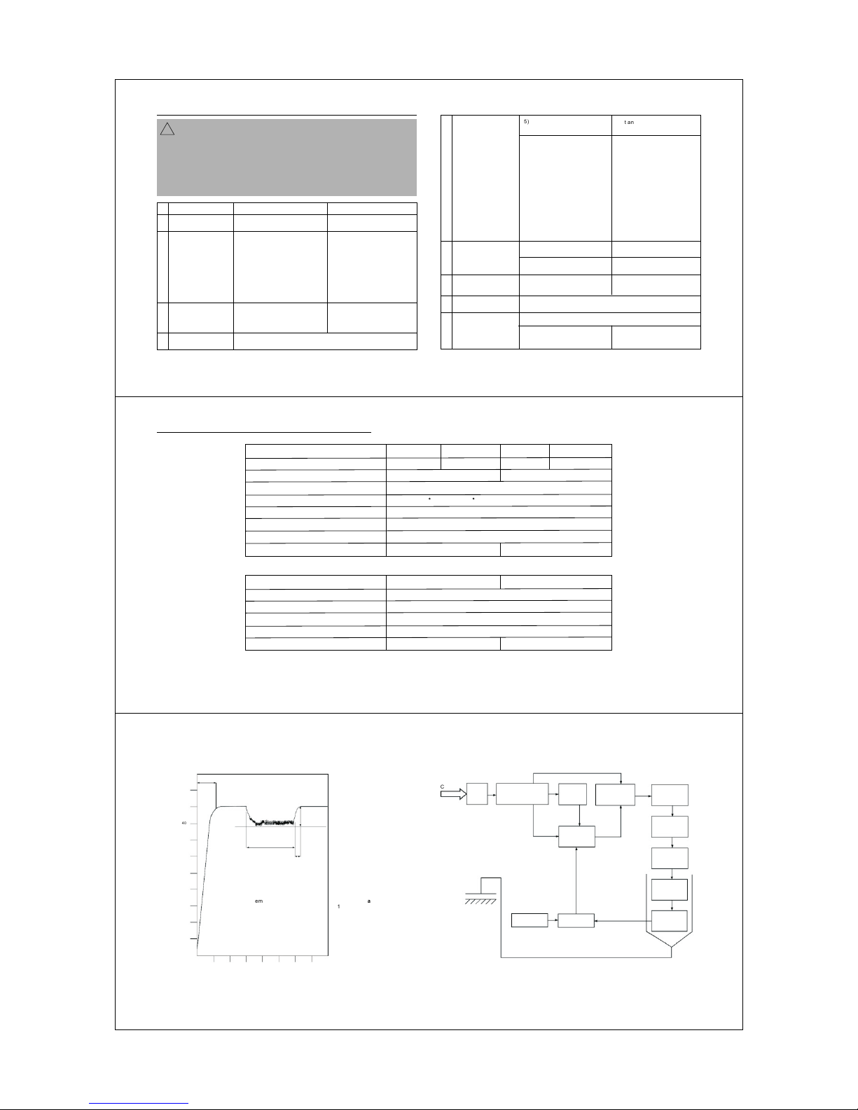
1. Working Temperature
A low temperature will slow the rate of flow of solder.
A high temperature will burn the flux in the solder, which
in turn will emit a heavy white smoke resulting in a dry
joint, or damage to the soldered components or parts.
When the Tip working temperature is set within the
correct parameters suited to the particular solder
being used, a good joint is assured. The most common
solder alloy used in the electronic industry is 60% tin,
40% lead. The typical working temperature of the solder
is detailed below but it can vary from manufacturer to
manufacturer.
Melting Point
Normal operation
Production line operation
Desoldering operation for small joint
Desoldering operation for large joint
The temperature above ( ) should not be used
for normal soldering functions, but can be used for short
period of time when excessive heat is required.
770 F 410 C
2.Use and Care of Tips
Tip Temperature
When Not in Use
Before Use and After Use
High soldering temperature can degrade the Tip.
Use the lowest possible soldering temperature.
The excellent thermal recovery characteristics of
this system ensures efficient and effective
soldering even at low temperature. This also
protects the soldered items from thermal damage.
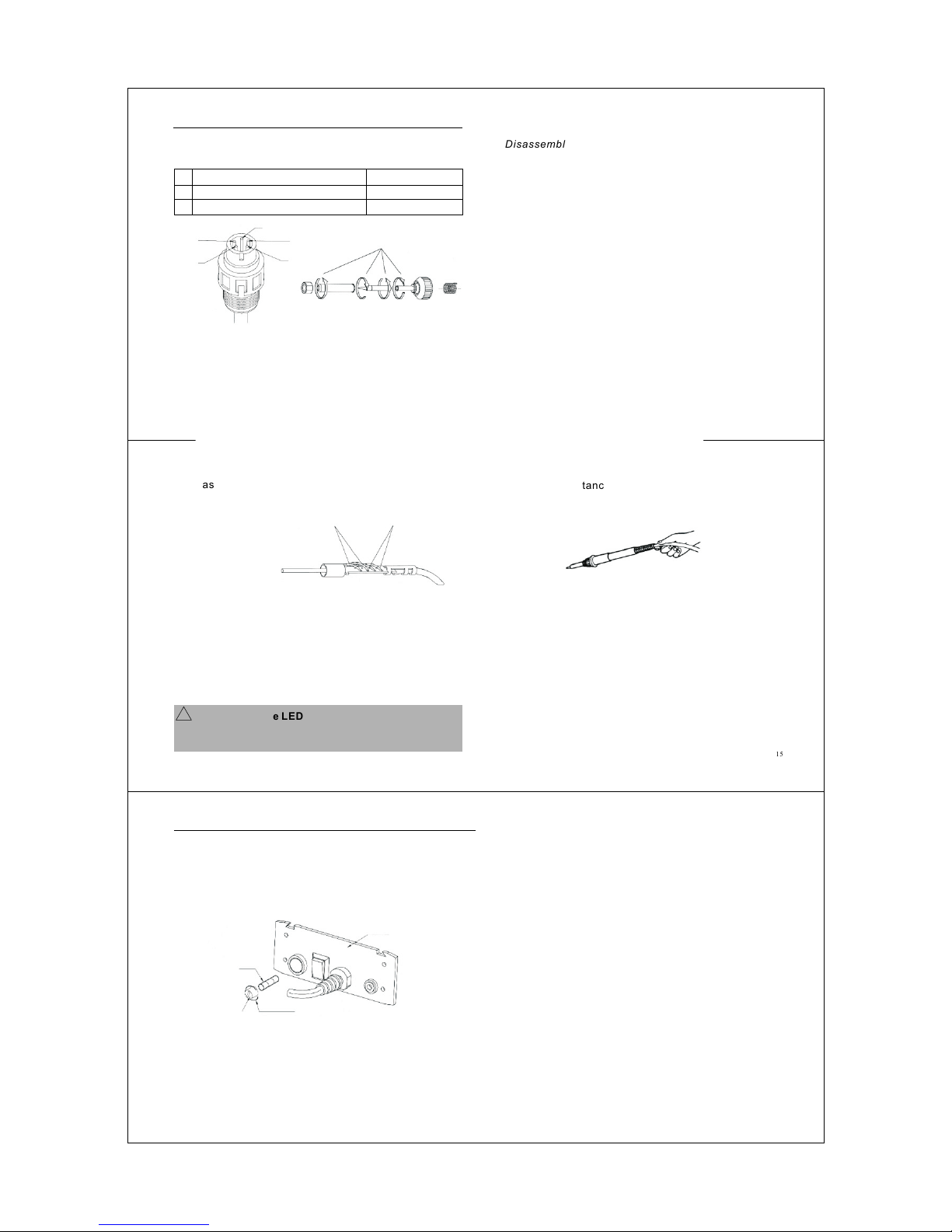
Clean the Tip regularly with the supplied Cleaning
Sponge, as oxides and carbides from the solder
and flux can form impurities on the Tip. These
impurities can reduce the Tip’s heat conductivity
or result in defective joints.
Wipe the Tip clean and coat the Tip with fresh solder.
This helps prevent Tip oxidation. Always keep the
11.
419 F (215 C)
608 F (320 C)
716 F (380 C)
608 F (320 C)
752 F (400 C)
Tip tinned before returning to Holder, switching off or storing
for any period of time,wipe only before using.
When using the Soldering lron continuously, be sure to
loosen the Tip and remove all oxides at least once a week.
This helps prevent seizure and reduction of the Tip
temperature.
Set the temperature to ( ).
When the temperature stabilizes, clean the Tip with the
Cleaning Sponge and check the condition of the Tip.
If black oxides appear on the solder-plated portion of the
Tip, apply new solder (containing flux). Wipe the Tip on the
Cleaning Sponge. Repeat until the oxides are completely
removed. Coat with new solder.
If the Tip is deformed or heavily eroded, replace with a new
one.
If any oxide film does form, this can be cleaned by carefully
rubbing with a 600-800 frit fine emery cloth, isopropyl
alcohol or the equivalent, then wrap rosin-core solder
around the newly exposed surface and reheat, flood the
482 F 250 C
Maintenance
tinned area with rosin-core solder after wrapped rosin-
core solder melted.
1.
2.
3.
5.
6.
!CAUTION
Do not
Do not
Do not
Never
keep lron set at high temperature for long period
of time as this will break down the surface of the Tip.
give any excessive pressure on a Tip or rubbing a
Tip on a joint during making a joint, it does not improve
heat transfer but only damages the Tip.
use fluxes containing chloride or acid, use only
rosin or resin activated fluxes.
remove Tip oxides with files.
12.
Calibrating lron Temperature
CAUTION: The Soldering System should be
recalibrated after changing the lron, or replacing the
Heating Element or Tip.
!
The initial temperature calibration of this Soldering
System has been set at the factory in accordance with
various industrial standards. No further calibration is
necessary by the user within about 6 months after first
use if no part change is needed.
1. Tools Required
1) Digital thermometer with leads and alligator clips
or digital thermometer equipped with surface
contact sensor specifically for Soldering lron
temperature measurement.
2) Test Tip fitted with thermocouple or SGT-710B
standard Tip for ceramic Heater.
3) 2.3-3mm (3/32” ) small flat screwdriver.
4) Multimeter
2. Steps of Calibrating lron Temperature
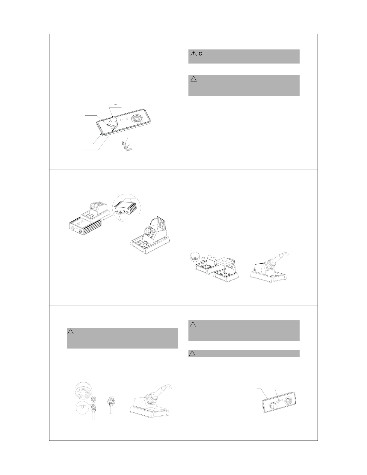
1) Connect the Cord Assembly Plug to the
Receptacle on the Control Base. (See Figure 11)
Set the Temperature Control Knob to
().
Remove the CAL Pot Plug on the Front Panel
(See Figure
and turn on the Power Switch.
Wait until the temperature stabilizes. Use a
small flat (-) or philips (+) screwdriver to adjust
the screw (through the CAL hole behind the
Front Panel at the Base) until the Tip
thermometer indicates the temperature to be
( ). Turn the CAL Screw slightly
clockwise to raise the temperature or
counterclockwise to lower the temperature.
Reposition the CAL Pot Plug.
750 400
750 400
2)
3)
4)
5)
!CAUTION: The
Soldering System
should be recalibrated
at the factory or service
agent if the 200
temperature scale
needs to be set.
(Figure 14)
Front Panel
CAL
Clockwise
Counterclockwise
CAL Pot Plug
13.