Spiker Scangauge User manual

Copyright © 2020 Spiker Engineering. All Rights Reserved.
’96-‘02 4Runner & ’96-‘00 Tacoma
Scangauge Mounting Bracket
Installation Instructions
NOTE: The latest version of the installation manual is on our website. Please download it and check its release date
against the date of this manual (highlighted in yellow below). Follow the instructions of the latest release date. Link to
manual - https://spikerengineering.com/installation
Thank you for purchasing the Spiker Engineering Scangauge Mounting Bracket. Please follow this manual carefully to
ensure a quality installation and many years of reliable service.
It is the customer’s responsibility to understand all of the work involved in the installation process, and to ensure
compatibility with their vehicle. No warranty is implied for the installation, and we will not be responsible for damage to
your truck, engine, or other parts, labor, personal injury, or any other damage or injury resulting from use of these
products.
Customer understands that all parts are aftermarket parts and have no OEM specifications.
If you have any questions or concerns at any point of the installation process, please contact us at
service@spikerengineering.com before proceeding, we’ll be happy to help.
Rev 7/4/2020
This manual is property of Spiker Engineering. Any unauthorized duplication or use without written permission from Spiker
Engineering violates Copyright laws.

Copyright © 2020 Spiker Engineering. All Rights Reserved.
This installation manual was written with emphasis on clearly illustrating and explaining every step involved. The actual
installation process is quite easy and should take less than 30 minutes. To get you started, below is an overview of the
steps involved in the installation:
Installation Steps:
(1) Preparation
(2) Remove the A-pillar handle
(3) Install the mounting bracket
(4) Route the cable
(5) Enjoy a beverage of your choice to celebrate!
The figure below provides an overall view of the components involved in the installation, please refer to it as you go
through the steps in the following sections.
Quick Start Guide

Copyright © 2020 Spiker Engineering. All Rights Reserved.
A. Check kit contents:
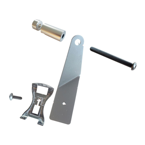
(1) Mounting Bracket (1) Adapter plate
(1) Bolt and locknut (1) Replacement M6 x 1.0 grab handle screw
B. Gather required tools
- Standard Mechanics Tool Set
You don’t need to remove the entire handle, just the lower mounting screw. First, pry off the lower screw cover with a
small flat blade screwdriver.
Now you can remove the Philips head M6 screw. The screw was factory installed with Loctite on the threads, so if you
have not removed this screw in the past, it may take some effort to remove it.
WARNING The screw is made of soft material, and it is very easy to strip the Phillips head it if you’re not careful, at
which point you’ll have to drill it out (good news is that it’s easy to drill it out because it is fairly soft). Timmy the
Toolman has a great video on removing the handle, starting at the 5:20 mark -
https://www.youtube.com/watch?v=fT_2szdKXRM&feature=youtu.be
To avoid stripping the screw head, use a cordless impact driver with a No. 2 JIS (not Philips) bit, such as the Motion Pro
JIS Crosshead Hex Drive Bit (No. 2) or the Makita Impact Bit:
Preparation
Remove the A-pillar Handle

Copyright © 2020 Spiker Engineering. All Rights Reserved.
Push hard on the screw head as you are loosening it, to avoid camout and stripping:
If you do strip a screw and have to drill it out, a replacement screw is included in the kit. Or you can get the OEM
Toyota screw P/N 90159-60254, or M6-1.0 x 25mm, like these - https://www.amazon.com/25-M6-Flange-Small-
Class/dp/B00N05XRMA
Pull the lower part of the handle away from the a-pillar, and slip the mounting bracket over the handle’s mounting post.
Note that the handle is usually “mushroomed”, so you may have to rock the bracket back and forth to slip it over the
mushroomed portion.
Once the bracket is installed over the handle, place the mounting post of the handle back into the a-pillar, and reinstall
the M6 screw (we recommend using the supplied high strength screw for easier future removals if necessary):
Place the adapter plate in front of the mounting bracket, and line up the holes, making sure that the cutout in the
adapter plate is on the right, as shown below. Secure the two brackets together with the bolt and nut provided. Don’t
fully tighten the nut at this point, to allow adjustments.
Install the Mounting Bracket

Copyright © 2020 Spiker Engineering. All Rights Reserved.
Sit in the driver’s seat, and adjust the tilt angle of the adapter plate to your liking, by rotating the adapter relative to the
mounting bracket. Once you’re satisfied with the tilt angle, tighten the locknut and the bolt (hint – tighten the locknut just
enough to be snug, to allow tilt adjustments later. The locknut will prevent loosening of the bolt.)
Clean the back of the Scangauge with IPA or similar. Remove the liner from the Dual Lock strips on the adapter plate,
and adhere the Scangauge to the Dual Lock strips, being careful to line up the Scangauge and the adapter plate. Press
the Scangauge against the Dual Lock strips on the adapter plate firmly to engage the adhesive, and hold tight for about
30 seconds.
The Dual Lock strips should be sufficient to hold the Scangauge, however you can add a couple of zip ties to hold the
Scangauge to the bracket even more securely.
Plug the cable into the back of the Scangauge. Leave a small loop near the Scangauge, then route the cable along the
a-pillar and to the left of the dash. You can also tuck the cable between the a-pillar and the door weatherstrip.
Once the cable is below the left part of the dash, remove the lower kick panel by removing the four M6 screws (10mm
head). Route the cable underneath the dash, keeping it high enough to avoid interference with pedals. You can zip-tie
the cable to other wire bundles under the dash.
Connect the cable to the OBDII port on the right side, by the gas pedal. Zip tie or tuck away any excess portion of the
cable, to ensure no interference with pedals.
If you have any questions or issues during installation, please email us at service@spikerengineering.com.
Finally, please post a product review and upload your installation photos at our webpage –
https://www.spikerengineering.com/product/scangauge-mount#reviews
Thank you again for purchasing this mount, we hope you enjoy it for many years to come!
Route the Ca le
Final Notes

Copyright © 2020 Spiker Engineering. All Rights Reserved.
Table of contents
Other Spiker Automobile Accessories manuals
Popular Automobile Accessories manuals by other brands
travall
travall TDG 1621D FITTING INSTRUCTION
Warn
Warn 101434 installation instructions
E&P HYDRAULICS
E&P HYDRAULICS Electronic Levelling System user manual
Prorack
Prorack K491 Fitting instructions
Metra Electronics
Metra Electronics 95-7617B installation instructions
Vision X
Vision X Solstice Solo Prime installation instructions
