Spinner BN 511411 User manual

Diese Bedienungsanleitung gilt für:
Bördelgerät für Kabel HCA118-50,HCA158-50, HCA295-50 und
HCA400-50
SPINNER BN 511411
M30399g
These instructions apply to:
Flanging tool for cable HCA118-50,HCA158-50, HCA295-50 and
HCA400-50
SPINNER BN 511411
M30399g
Lesen Sie bitte vor Inbetriebnahme diese Anleitung, die für qualifi-
ziertes und geschultes Personal geschrieben ist, sorgfältig durch. Bei
unsachgemäßem Gebrauch ist eine Haftung bzw. Gewährleistung
ausgeschlossen! Bitte beachten Sie bei Montage und Entsorgung die
geltenden Umweltschutzbestimmungen!
Bördelgerät, Fig. 1
Bördelgerät mit montiertem
Einsatzring entspr. Kabeltyp
und Kabelabfangung (Aus-
führung: Premium)
Einsatzringe können gem.
Tabelle bestellt werden:
Für Kabel HCA400-50 ist
kein Einsatzring erforderlich!
Vorbereitung, Fig. 2
Bördelrolle auf Leicht-
gängigkeit und Verschleiß
prüfen, dabei mit Synthesin
PDL250 oder anderem
geeigneten Fett oder Öl
schmieren.
AbstandX(s.Detail)zwischen
Bördelrolle und Bördelfläche
der Kabelabfangung mit
selbstsichernder Mutter ein-
stellen: Schneidvorrichtung,
falls erforderlich mit Hebel
aus der Schneidstellung in
Ruhelage schwenken und
einrasten. Falls notwendig
den zur Kabelabfangung pas-
sendenEinsatzringeinsetzen.
Bördelgerät mit Schrauben A
auf dem Einsatzring befesti-
gen. Leere Kabelabfangung
einsetzen und die Bördelrolle
durch Drehen am Zahnrad
über die Bördelfläche ver-
schieben. Mittels selbstsi-
chernder Mutter denAbstand
X zwischen Bördelrolle und Kabelabfangung einstellen.
Bedienungsanleitung
lnstructions for Use
These instructions were written for qualified and experienced personnel.
Please read them carefully before starting work.Any liability or warranty
for the results of improper or unsafe use is disclaimed! Please respect
valid environmental regulations for assembly and waste disposal!
Flanging tool, Fig. 1
Flanging tool with assembled
ring-shaped insert according
to cable type and connec-
tor back end (version: pre-
mium)
Ring-shaped inserts can be
ordered according to table:
No ring-shaped insert neces-
sary for cable HCA400-50!
Preparation, Fig. 2
Check easy-running and
abrasion of flaring roll, grease
with Synthesin PDL250 or
other applicable grease or oil.
Adjust distance X(see detail)
between flaring roll and flar-
ing area of the connector
back end with self-locking
nut. If necessary, move
cutting device out of cut-
ting position with lever and
let it snap into position of
rest. If necessary, install the
ring-shaped insert, which
matches the connector back
end. Fix flaring tool with screws
Aonto ring-shaped insert.
Insert the empty connector
back end and slide the flar-
ing roll over the flaring area
by turning the toothed wheel.
Adjust distance Xbetween
flaring roll and flaring area of
the connector back end with
self-locking nut. Seite 1/3
page 1/3
Best. Nr.
Order no.
Kabelabfangung, Ausführung:
Connector back end,version:
Kabel:
Cable:
BN 511447 Premium/premium HCA118-50
BN 511457 Premium/premium HCA158-50
BN 511481 Premium/premium HCA295-50
Z Bördelrolle / flaring roll Kabel / Cable Maß / Dimension X
HCA118-50 0.50 mm
HCA158-50 0.50 mm
HCA295-50 0.60 mm
HCA400-50 0.70 mm
Z

Bördeln, Fig. 3
Kabelabfangung auf das
Kabel bis zum Anschlag
schrauben, in das Bördel-
gerät einsetzen und mit den
Schrauben Bbefestigen.
Hinweis: Die Schrauben
B(M6x16, DIN912) für die
Kabelgröße HCA400-50 lie-
gen dem Werkzeug bei. Für
alle anderen Kabelgrößen
werden die Schrauben der
Kabelabfangung verwendet!
Die Bördelrolle durch
Drehen am Zahnrad in eine
Stellung bringen, die sich
zwischen Kabelinnenleiter
und Kabelaußenleiter
befindet. Falls erforderlich,
Bördelrolle durch Drehen
am Zahnrad einstellen, bis
sie den innersten Rand des
Kabelaußenleiters berührt.
Durch Drehen der Kurbel
in Pfeilrichtung Bördelung
durchführen. Falls erforder-
lich, mit gleicher Einstellung
Bördelung wiederholen.
Abschneiden, Fig. 4
Hebel drücken und
Schneidvorrichtung in Ar-
beitsposition schwenken.
Darauf achten, dass sich
die Kurbel frei drehen
lässt. Falls erforderlich
Schneidvorrichtung durch
Drehen am Zahnrad ein-
stellen, bis der Schneidstahl
den äußersten Rand des
Kabelaußenleiters berührt.
Der Schneidstahl soll-
te sich auf dem äußers-
ten Rand des gebördelten
Kabelaußenleiters befin-
den. Kurbel gegen die
Pfeilrichtung drehen, bis
der Kabelaußenleiter den
Vorgaben gem. der Stecker-
Montageanleitungentspricht.
Achtung: Während des
SchneidvorgangesHöhedes
Schneidstahles durch Lösen
der Rändelmutter so einstel-
len dass der Schneidstahl
die Kabelabfangung nicht
beschädigt.
Schneidstahl, Fig. 5
Nachschleifen und Ein-
stellung
Schmierung, Fig. 6
Schmierung mit Synthesin
PDL250oderanderemgeeig-
neten Fett an den gekenn-
zeichneten Stellen nach ca.
500 Bördelvorgängen. Das
Lager ist auf Lebensdauer
geschmiert.
Flaring
Fig. 3
Screw connector back end
on cable until stop, insert it
into the flaring device and fix
it with screws B.
Note: The screws B(M6x16,
DIN912) for cable size
HCA400-50 are added to
the flaring tool. For all other
cable sizes use the screws
of the connector back.
Move the flaring roll into in a
position between the cable
inner conductor and cable
outer conductor by turning
the toothed wheel.
If necessary, move flaring roll
by turning the toothed wheel
until it touches the inner-
most edge of the cable outer
conductor.
Flare by turning the crank in
direction of the arrow.
If necessary, repeat flaring in
the same position.
Cutting, Fig. 4
Press lever and move cutting
device into working position.
Pay attention, that the crank
can be turned around. If
necessary adjust the cutting
device by turning the toothed
wheel until the cutting alloy
contacts the outside frame of
the cable outer conductor.
The cutting alloy should be
positioned above the maxi-
mum possible edge of the
flared cable outer conductor.
Move crank counter clock-
wiseuntil cableouterconduc-
tor is according to connec-
tor-installation instructions.
Attention: Adjust the height
of the cutting alloy during cut-
ting by loosening the knurled
nut. The connector back end
should not be marked by the
cutting alloy.
Cutting alloy, Fig. 5
Abrading and adjustment
Greasing, Fig. 6
Greasing with Synthesin
PDL250 or other applica-
ble grease on the marked
points after approx. 500
applications. Bearing is
greased for life.
Seite 2/3
page 2/3
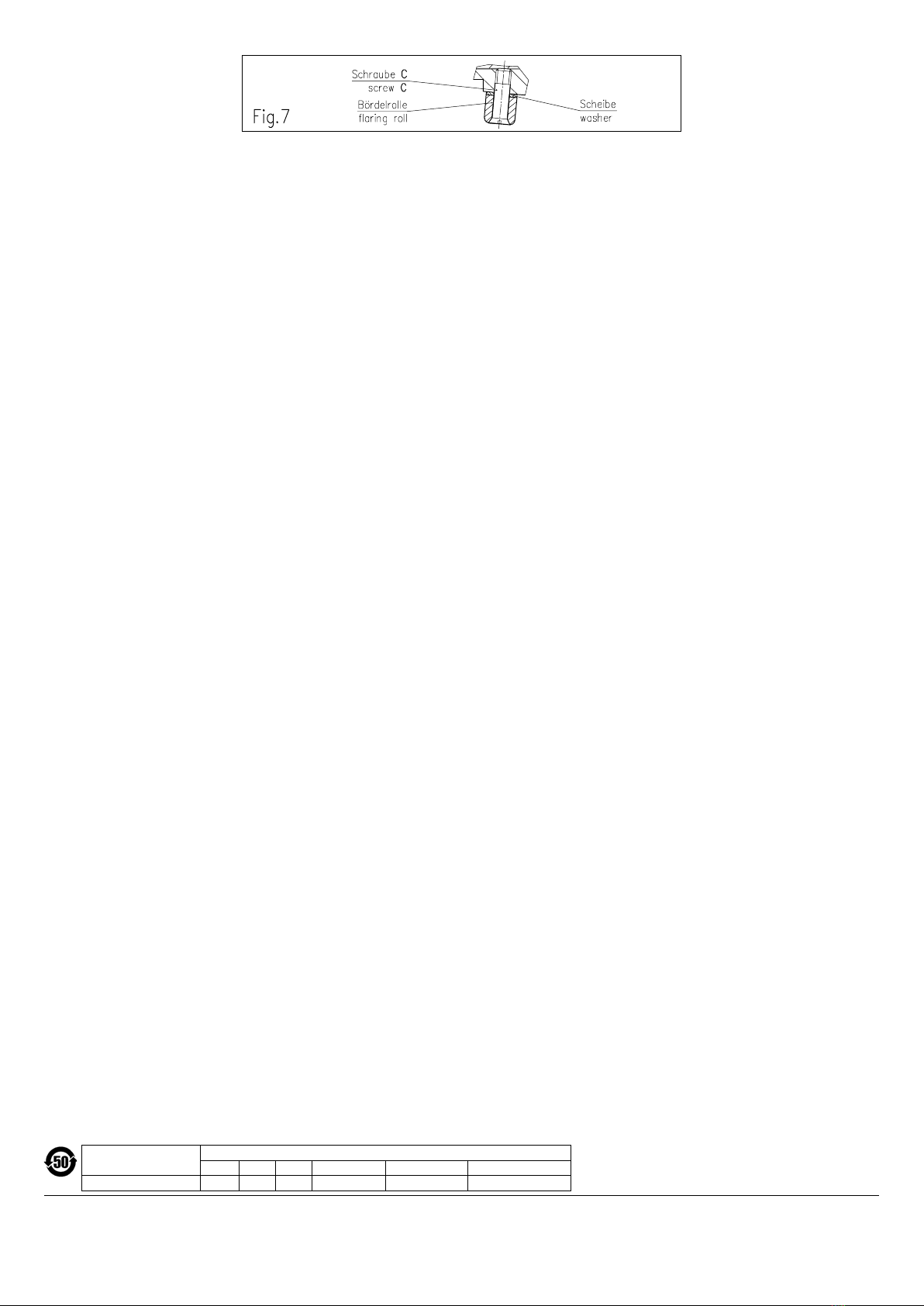
Wechsel der Bördelrolle, Fig. 7
Ist die Bördelrolle verschlis-
sen,muss siealsBestandteil
eines Ersatzteilsatzes
gewechselt werden. Dazu
Schraube Cherausdre-
hen und Bördelrolle und
Scheibe entnehmen. Ersatzteile (Bördelrolle und Scheibe) mit Fett
einsetzen. Schraube Ceinschrauben, dabei mit Loctite 270 oder
gleichwertigem Kleber verkleben.
Leichtgängigkeit der Bördelrolle prüfen!
Ersatzteilsatz kann bestellt werden unter:
SPINNER BN B18340
Replacing the flaring roll, Fig. 7
If the flaring roll is worn, it
has to be replaced as part
of a spare part set. Remove
screw Cand take out flaring
roll and washer. Install grea-
sed spare parts
(flaring roll and washer). Tighten screw Clocking it with Loctite 270
or similar adhesive.
Check easy-running of flaring roll!
Spare part set can be ordered under:
SPINNER BN B18340
SPINNER GmbH
Erzgiessereistr. 33 • 80335 München • Germany
Phone +49 89 12601-0 • Fax +49 89 12601-1292
www.spinner-group.com
产品在正常使用条件下, 其环保使用期限才在此标识有效
期内. / The environmental protection use period is valid
if the product is used as intended.
部件名称/Component
Name
有毒有害物质或元素/Toxic or Hazardous Substances and Elements
铅/Pb 汞/Hg 镉/Cd 六价铬/Cr 6+ 多溴联f/PBB 多溴二f醚/PBDE
金属零件/metal parts X O O O O O
Seite 3/3
page 3/3


