Spinning Spinner Pro User manual
Commercial Bike Assembly Guide
and Owner’s Manual
NXT
PRO
Chrono
PRO Power
TM
NXT PowerTM
SPINNING®
www.spinning.com

CONTENTS
Getting Started Guide Page 3
Program Safety Page 5
Assembly Guide Page 6
Bike Maintenance Page 12
Warranty Page 15
Trademark Usage Page 21

www.spinning.com 3
SPINNING®
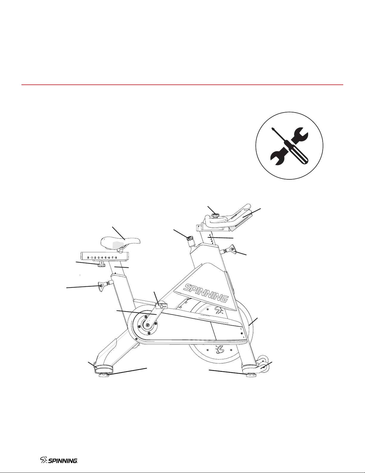
GETTING STARTED
Part
Seat Adjustment Pop-Pin
Seat Slider knob
Part
Handlebar Adjustment Pop-Pin
Fore/aft Handlebar Knob
Resistance Knob
1
1
1
3
3
2
2 4
5
5
4
Set up the bike
Seat Height
Reduce your risk of injury and enjoy a more comfortable ride
by adjusting the seat height so that there is a slight bend
(25-35 degrees) in your knee at the bottom of a pedal stroke.
To adjust the seat height:
1. Dismount the bike. Turn and pull the seat adjustment
pop-pin counterclockwise (–) to loosen and release it
from the seat post.
2. Raise or lower the seat to the desired height.
3. Turn the pop-pin clockwise (+) and secure it in a preset hole.
Now adjust the seat’s horizontal position so you sit on the
bike with the pedals parallel to the floor, and your forward
knee is aligned over the center of the pedal.
To adjust the horizontal seat:
1. Dismount the bike. Turn the seat slider knob
counterclockwise (–) and move the seat to the desired
position.
2. Fully tighten the seat slider knob by turning it clockwise (+).
3. Recheck the seat height to make sure there’s a slight
bend in your knee.
Handlebar Height
The handlebar should be approximately the same height as
the seat, or higher if you feel back discomfort.
To adjust the handlebar height:
1. Turn the handlebar adjustment pop-pin counterclockwise
(–) to loosen and release it from the post.
2. Raise or lower the handlebars to the desired height, then
secure the pop-pin in a preset hole.
3. Turn the handlebar adjustment pop-pin clockwise (+) to
fully tighten it.
To adjust the fore/aft handlebar position:
1. Turn the fore/aft handlebar knob counterclockwise (-)
to loosen it.
2. Slide the handlebar assembly to the desired position and
then fully tighten the fore/aft handlebar knob.
The Spinner® line of indoor cycling bikes sets the standard for adjustability,
comfort, and performance. Together with the Spinning® program, Spinning®
provides an unparalleled experience for studios and gyms worldwide.
Before you start, you can learn more about Safety, Maintenance, Spinning®
Accessories, Training, and the Spinning® Community by visiting us at
www.spinning.com.
2
3
4

4
Foot Position
Place the balls of your feet securely on the center of the pedals.
Foot Strap
Adjust the toe straps to hold your foot firmly on the pedal,
allowing you to apply force throughout every part of the
pedal stroke.
SPD-compatible Side of Pedal
Place the cleat over the SPD-compatible mechanism and
apply pressure to secure cleat. Make sure cleat is securely
connected. To disconnect, push heel outward.
Note If your foot comes loose when riding, firmly press down
on the resistance knob to stop and secure your foot.
Resistance Control and Stop Function
Turn the resistance knob 5 to change the pedaling resistance.
Press down on the knob to stop the flywheel and pedals.
• To increase or decrease resistance, turn the knob
clockwise (+) or counterclockwise (-).
• To stop the flywheel and pedals from moving, firmly
press down on the resistance knob to bring the flywheel
and pedals to a stop.
Ride the bike
CAUTION: Before beginning any fitness program, see your physician for a thorough medical exam.
Ask your physician for the appropriate target heart rate for your fitness level.
Failure to follow these safety instructions can result in serious personal injury.
Step 1: Set up the bike so that the seat and handlebars
are properly adjusted for your height and comfort.
Important: Make sure that all pop-pins are engaged
and fully tightened after adjusting your bike.
Step 2: Mount the bike and secure your shoes in the
toe straps or toe clips.
When you sit on the bike with the pedals parallel to
the floor, your forward knee should be aligned over
the center of the pedal. Turn the resistance knob
clockwise (+) to gradually increase the tension.
To vary the intensity of your workout, adjust the knob
while riding.
Step 3: To dismount, firmly press down on the resistance knob.
Do not dismount the bike until the pedals and flywheel have come to a complete stop.
After each workout
For commercial bikes:
• Release all tension from the resistance knob after each use to allow for perspiration to evaporate. If bikes are used in a
class setting, the instructor should direct class participants to release all tension from the resistance knob after each use.
For bikes used in a home setting:
• Wipe down the bike after each use. Pay special attention to wipe under the resistance knob.
• When done, turn the resistance knob clockwise (+) to put tension on the flywheel so that the pedals do not rotate freely.
• When the bike is not in use, always keep some resistance on the flywheel.
5

www.spinning.com 5
• Consult your physician prior to beginning this or any other exercise program. Not all exercise routines are suitable for
everyone. Discontinue any exercise that causes you discomfort and consult a medical expert.
• Ensure that the adjustment knobs (saddle height, saddle fore/aft and handlebar height) are properly secured and do not
interfere with your pedaling of motion.
• Children under the age of 16 should not ride the Spinner®bike.
• Do not insert any object, hand or foot into any openings. Do not expose hands, arms or feet to the drive mechanism or
any other potentially moving parts of the bike.
• The body weight for individuals riding the Spinner®bikes should not exceed 350 pounds (159 kg).
• Spinner®bikes have a weighted flywheel and a fixed gear that do not allow riders to coast. This means that in order to
stop, you must gradually slow your pedal strokes rather than stopping abruptly. If you need to stop immediately, push
down on the red resistance knob.
• After use, turn the knob clockwise to increase the resistance so that the pedals will not rotate freely.
• If at any time you feel dizzy or have diculty breathing, press down on the red resistance knob until you come to a
complete stop and carefully dismount the bike.
• Listen to your body, ride at your own pace, and set a resistance load that feels right for you.
• Keep children and pets away from the bike whenever it is in use.
• Stay hydrated. Drink plenty of water throughout your ride.
• During warm-up and cool-down, pedal with a light amount of resistance at all times, The Spinning®program reminds riders
to maintain a connection to the flywheel with resistance throughout the ride.
• Stay in control by executing all movements and hand positions at a slow pace before attempting to increase your pedaling
speed.
• Focus on form, posture and smooth transitions between movements.
• Always ride with proper footwear. Do not ride with bare feet or open-toed shoes.
• Keep shoe laces tucked in and foot straps snug around your shoe. If your foot does come out of the toe clip, push down
on the resistance knob to stop the flywheel’s motion before clipping back in.
SPINNING®
PROGRAM SAFETY
6
SPINNING®
ASSEMBLY GUIDE
Seat assembly
Handlebar
assembly
Rear
stabilizer
Seat post
Handlebar post
Front
stabilizer
Pedal
Seat adjustment
pop-pin
Handlebar
adjustment
pop-pin
Seat
slider knob
Fore/aft handlebar
knob
Resistance
knob
Flywheel
Adjustment feet
Crank arm
www.spinning.com 7
1. Push bars down onto post.
2. Install and tighten the flat head counter sunk screws
on the front of the post.
3. Install and tighten the set screw in the rear of the
post.
4. Pull the pop-pin out.
5. Insert head post into frame.
6. Tighten pop-pin (clockwise).
1. Slide bars from back to front onto the fixed post.
2. Use two 3mm screws to secure the endcap on the fixed
post.
3. Tighten the adjustment knob.
4. Go to step 6 (tighten pop-pin, clockwise).
12
3
4
5
all models
clockwise to tighten
fixed bar
1
2
3
ASSEMBLE THE BARS
adjustable bar
6

8
INSTALL THE REAR STABILIZER
For safety, make sure that
one person steadies the
bike while the other person
installs the stabilizer.
Place washers on each stabilizer bolt
and use the supplied hex key to tighten
each bolt securely (turn clockwise).
!
TILT THE BIKE FORWARD
1
!
2
!
1. To avoid damage, ensure that the bike is
on carpet, cardboard or other soft surface.
2. With 2 people, pivot the bike forward and
gently rest it in a vertical position on the
handlebars.
One person should always
hold the bike steady when
in this position.
!

www.spinning.com 9
3
4
2
1
1
2
3
1. Pull the pop-pin back.
2. Insert the seatpost assembly into glide.
3. Secure the seatpost by releasing the pop-pin into an
adjustment hole and turning the pop-pin (clockwise).
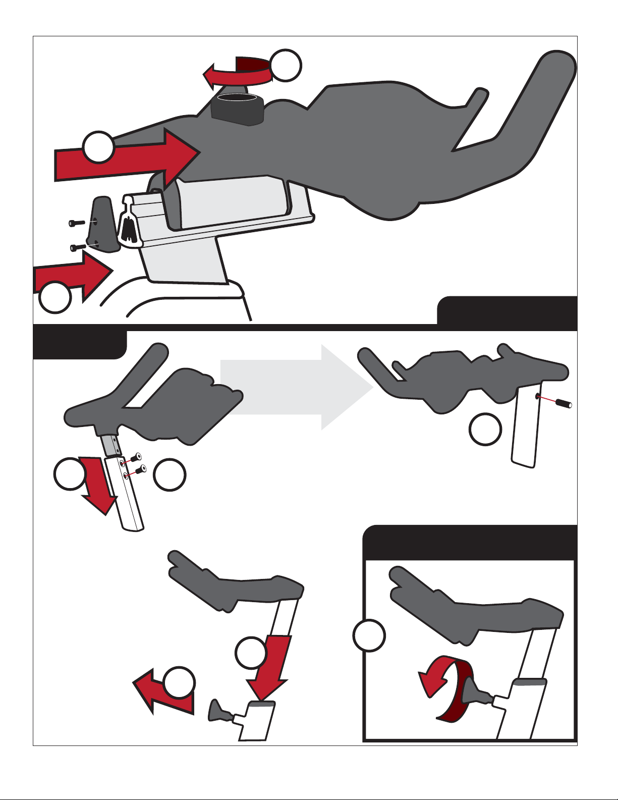
ASSEMBLE THE SEAT SLIDER
INSTALL THE SEAT SLIDER ASSEMBLY
1. Slide seat slider onto post.
2. Tighten adjustment knob.
3. Ensure that the assembly is
positioned as shown and install
the 3mm limiting screw.
4. Install endcap using three 3mm
screws.

10
One person should always
hold the bike steady when
in this position.
1. To avoid damage, ensure that the bike is
on carpet, cardboard or other soft surface.
2. With 2 people, pivot the bike rearward
and gently rest it in a vertical position on
the seatpost.
TILT THE BIKE REARWARD
INSTALL THE FRONT STABILIZER
2
1
!
!
WHEELS POINT TO THE
FRONT OF THE BIKE
For safety, make sure that
one person steadies the
bike while the other person
installs the stabilizer.
Place washers on each stabilizer bolt
and use the supplied hex key to tighten
each bolt securely (turn clockwise).
!
!

www.spinning.com 11
LEVEL THE BIKE
See Integrated Power Console supplement for details.
INTEGRATED POWER CONSOLE
ADDITIONAL STEPS FOR BIKES EQUIPPED WITH THE
SPINPOWER CRANK AND INTEGRATED POWER CONSOLE
CALIBRATE THE SPINPOWER CRANK
Download the SPINPower Crank Connect app available free for Apple and Android devices and follow the
on-screen instructions to calibrate your crank. You can also rename your crank, check for firmware updates and
check the battery life, all from your mobile device. See the Studio SPINPower Crank supplement for more info.
1. Place the pedal into the morse taper hole, orienting
the toe clip side on top and facing the front of the
bike.
2. Use a rubber mallet to gently tap the pedal into the
machined pedal hole on the crank.
3. Hand thread the pedal bolts into the back of the
crank. Use a hex key to torque to 35ft-lbs (45 N-m)
INSTALL THE PEDALS
1
2
3
RUBBER MALLET
Make sure that the bike is
level and securely sitting
on all 4 feet. If there is any
rocking or instability,
rotate the appropriate
adjustable foot until the
bike is level and stable.

12
Before you begin
• Spinning® recommends owners implement a thorough maintenance program that incorporates regular safety inspections
by qualified maintenance technicians as outlined in this Maintenance Guide (“Guide”). Also, Spinning® recommends that
technicians thoroughly read and understand the safety guidelines and maintenance procedures covered in this Guide.
• This Guide provides information about items that need to be inspected and maintained on a daily, weekly, and monthly basis.
• It is the duty of the gym or studio owner or bike owner, during maintenance, to place an “Out Of Order” sign on the bike.
Important: It is the duty of the owner to maintain equipment in accordance with the instructions in this material and any
accompanying material. Always purchase replacement parts and hardware from Spinning®. If you use parts not approved
by Spinning®, you could void the Spinning® Limited Warranty. Use of parts not approved by Spinning® may cause injury
and potential damage to your equipment.
Recommended Tools
• Standard set of hex keys
General Care
• Never use abrasive cleaning liquids, degreasers or petroleum-based solvents on the bike. Use a soft nylon scrub brush to
clean grooves and textured surfaces.
For commercial bikes:
o Release all tension from the resistance knob after each use to allow for perspiration to evaporate. If bikes are used in a
class setting, the instructor should direct class participants to release all tension from the resistance knob after each use.
For bikes used in a home setting:
o Wipe down the bike after each use. When done, turn the resistance knob clockwise (+) to put tension on the
flywheel so that the pedals do not rotate freely.
o When the bike is not in use, always keep some resistance on the flywheel.
• Clean all surfaces of the frame and plastic components. Keep excess moisture away from electronic components and
dry completely with a lint-free cloth to prevent electrical shock or damage.
• After the first ten hours of use and every 100 hours of use thereafter, re-torque the pedals to 33 ft-lb (45 N-m).
Daily Maintenance Tasks
Note: Raise seat and handlebar posts to their highest setting to expose moisture.
• Wipe the bike frame using a clean lint-free cloth dampened with 30 parts water to 1 part non-abrasive detergent.
• Use a lint-free cloth to dry the bike. Pay special attention to the handlebar, pop-pins, resistance knob, chain guard,
flywheel, and seat adjustment assembly.
• Check warning and instruction labels.
Weekly Maintenance Tasks
• Clean the floor under the equipment. Do not lift and hold equipment while vacuuming or mopping.
• Ride each bike to identify any vibration, noises, and chain issues.
• Check for flywheel alignment.
• Inspect each bike for loose assemblies, parts, bolts and nuts. Give particular attention to the following:
o Frame hardware
o Seat and handlebar hardware including knobs and pop-pin handles
o Toe straps/toe clips
SPINNING®
BIKE MAINTENANCE
www.spinning.com 13
Monthly Maintenance Tasks
The monthly maintenance check is a comprehensive inspection of the entire bike frame and hardware in addition to the
weekly maintenance tasks.
• Inspect the bike for rust or corrosion.
• Check flywheel alignment and torque flywheel nuts as necessary.
• Remove chain guard and check for loose belt. Adjust belt as necessary.
• Use a soft nylon scrub brush to remove rust build-up in small crevasses, such as pedals and pop-pin threaded stems.
• Inspect all wear items for adjustments or possible part replacement. Give particular attention to the following:
o Inspect brake pad for wear. Excessive wear, such as glazing or leather separation, indicates replacement is required.
o Inspect seat for wear. Rips, tears, or excessive movement indicates replacement is required.
o Tighten seat hardware.
o Inspect pedals for excessive wear or movement. Excessive wear or movement indicates replacement is required.
o Tighten pedal toe and toe clips and inspect toe straps for excessive wear.
o Inspect and tighten resistance knob assembly.
o Level feet.
• Clean and seal the bike frame. Sweat can corrode the bike frame. Spinning® recommends that you seal the bike frame
at least once a month with equipment polish.
To seal the bike frame:
1. Wipe the bike frame using a clean lint-free cloth dampened with 30 parts water to 1 part non-abrasive detergent.
2. Rinse the bike frame using a clean lint-free cloth and dampened with water only. Dry completely with another clean lint-
free cloth.
3. Seal the bike frame using wax or a polish to repel sweat and liquids. For best results, apply the wax or polish per
manufacturer’s instructions.
Replacement Parts
Depending on the use and maintenance of the product, certain items can be replaced on a schedule. The list below shows
the components that can be replaced on a schedule to keep the bike in top working order.
Part Replacement Schedule
Brake Pad Assembly 2 years
Belt 2 years
Pedals 2 years
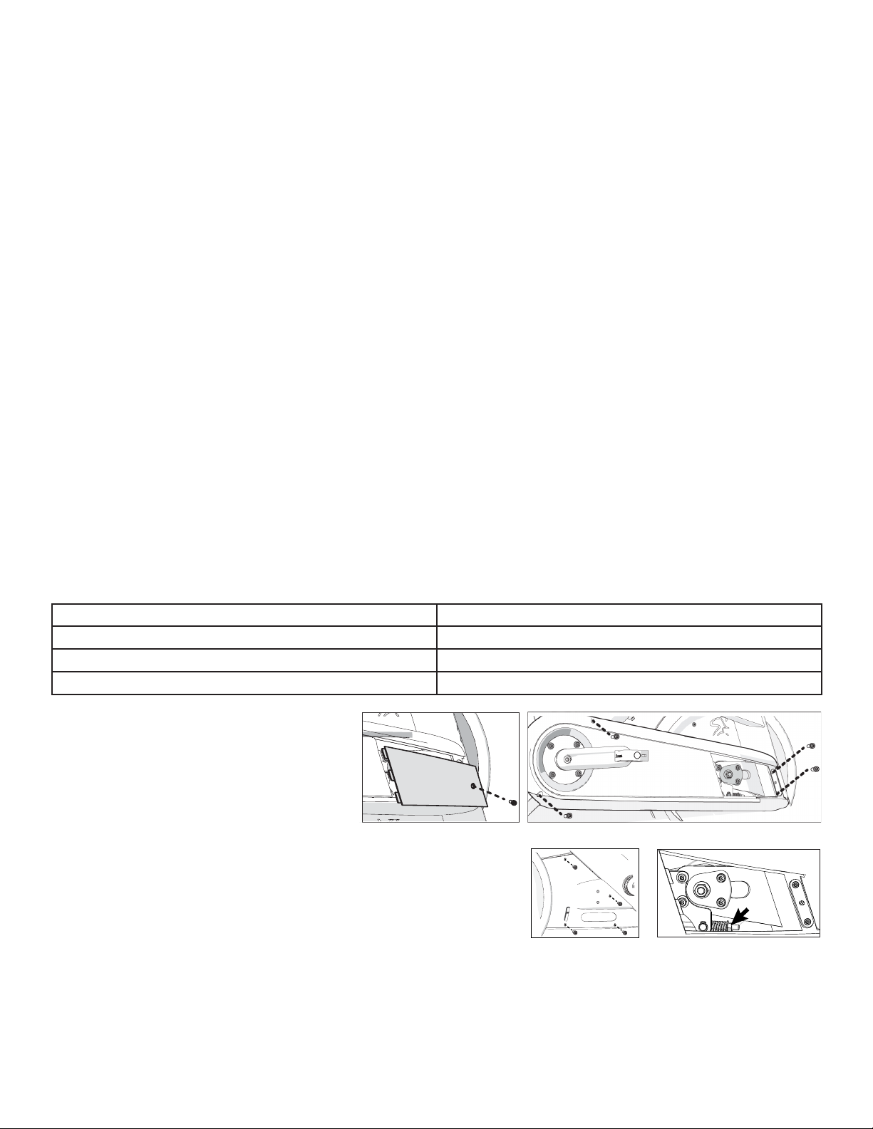
Adjust the Belt
Important: Adjust the belt only if you are
experiencing slippage under high resistance.
Improper belt adjustment will cause premature
wear and may void the Spinning® Bike Limited
Warranty.
To adjust the belt:
1. Loosen the bolt and remove the cover window (Figures 1).
2. Loosen the four bolts holding on the cover and remove it (Figure 2).
3. Remove the four bolts holding on the back cover and remove it (Figure 3).
4. Turn the nut clockwise one full turn. Ride the bike at high resistance. If you still experience slippage, turn the nut
clockwise one more full turn. Repeat until there is no slippage. (Figure 4).
Important: If the belt is stretched beyond adjustment, replacement of the belt is recommended.
5. Check that the belt moves smoothly by slowly turning the crank arm while keeping your fingers away from the belt.
6. Replace the covers.
Figure 1 Figure 2
Figure 3 Figure 4

14
Replace the Brake Pad (Friction-Resistant Bikes)
Your bike comes with a spare brake pad. To order more pads,
contact Spinning® Customer Support.
To replace the brake pad:
1. Remove tension from the brake pad by turning the resistance
knob counterclockwise (–) until completely loose.
2. Using a 5 mm hex key, remove the two bolts holding the
brake pad against the frame (Figure 5).
3. Remove the bolt on the brake pad with a 3 mm hex key
(Figure 6).
4. Replace the brake pad and secure it with the bolt removed in
Step 3.
5. Pull up the resistance knob and slide the new brake pad into
place. Secure it using the two bolts removed in Step 2.
Figure 5 Figure 6

www.spinning.com 15
Limited Warranty
PLEASE READ THESE WARRANTY TERMS AND CONDITIONS
CAREFULLY BEFORE USING YOUR SPINNING® PRODUCT.
BY USING THE EQUIPMENT, YOU ARE CONSENTING TO BE BOUND
BY THE FOLLOWING WARRANTY TERMS AND CONIDTIONS.
Mad Dogg Athletics, Inc. (MDA) warrants all new products to be
free from defects in materials and manufacture for the warranty periods
set forth below. The warranty periods commence on the invoice date
of the original purchase. This warranty applies only against defects
discovered within the warranty period and extends only to the original
purchaser of the product. Parts repaired or replaced under the terms of
this warranty will be warranted for the remainder of the original warranty
period only. To claim under this warranty, the buyer must notify MDA
or your authorized Spinning® Distributor within 30 days after the date of
discovery of any nonconformity and make the aected product available
for inspection by MDA or its service representative. MDA’s obligations
under this warranty are limited as set forth below.
SPINNING®
SPINNER® BIKE LINE LIMITED WARRANTY

16
Warranty Periods and Coverage.
All Commercial indoor cycles manufactured and sold after January 1, 2023,
subject to the terms and conditions set forth herein:
Spinner PRO®
PRO™ Power
Spinner NXT®
NXT™ Power
Spinner Chrono®
Frame 7 years 10 years
Mechanical Parts 2 years
Labor 1 year
Wear Items 90 days
Console 1 year
Limited Extended Warranty and Coverage.
To the extent the original purchaser purchases a limited extended warranty
for Spinner® Bike Line of products as set forth in a signed Product Quote that has
been accepted by Spinning®, then such limited extended warranty (i) shall only
apply to Mechanical and Electrical parts and Product Labor, if applicable, (ii)
shall commence on the invoice date of the original purchase, (iii) shall replace,
and not be in addition to, the warranty periods for Mechanical and Electric
parts and Product Labor set forth above (e.g., the standard warranty period
and the extended warranty period shall NOT be cumulative), and (iv) shall be
subject to all the terms and conditions set forth herein.
In no event shall any limited extended warranty apply to the following parts:
• Wear Items, including: Headphone Jacks, Batteries, Pedals, Toe Straps, Seats and Belts.
Spinner® Bike Line Limited Warranty

www.spinning.com 17
Conditions and Restrictions.
This warranty is valid only in accordance with the conditions set forth below:
1. The warranty applies to the Spinning® product only if:
a. it has been serviced by a Spinning® Authorized Service Provider and/or
Spinning® Certified facility sta. Outside of North America, such product
must be serviced by Spinning® oce or Spinning® Authorized Distributors.
b. it remains in the possession of the original purchaser and proof of
purchase is demonstrated.
c. it has not been subjected to accident, misuse, abuse, improper
service, or non-Spinning® modification.
d. claims are made within the warranty period.
2. This warranty does not cover damage or equipment failure caused by
owner’s failure to provide reasonable and necessary maintenance as outlined in
the owner’s manual.
3. Spinning® is not responsible for Internet connectivity to its products.
This restriction applies to services, such as those provided by an
Internet service provider (ISP), and also to hardware related to Internet
connectivity, such as Ethernet cabling, routers, servers and switches.
4. Spinning® is not responsible for the quality of video, audio, or other
media supplied to its products. This restriction applies to services, such as
those provided by a cable or satellite television provider; to signal strength
and clarity; and also to hardware related to the reception and delivery
of television, video, audio, and other media. Such hardware can include
(but is not limited to) audio, video, and radio-frequency (RF) cabling,
connectors, receivers, modulators, combiners, distribution amplifiers,
splitters, and so on.
5. Spinning® cannot guarantee that the heart rate measurement system on its
products will work for all users. Heart rate measurement accuracy varies
based on a number of factors, including the user’s physiology and age,
the method in which the heart rate measurement system is used, external
interference, and other factors that may influence heart rate acquisition.
6. Spinning® does not warranty the work or product of third party companies
(e.g., head end systems, low voltage wiring, etc.).
Conditions and Restrictions.

18
7. Except in Canada, Spinning® does not pay labor outside the United States.
Equipment limited warranty is void when equipment is installed in a
country other than where sold.
8. Moving parts bolted to the structural frame are not included in the
“Structural Frame” warranty
9. In the case of commercial indoor cycle products sold into a residential
(home) environment, the term of limited warranty coverage remains the
same regardless of where the equipment is installed or used.
This Limited Warranty shall not apply to:
1. Software updates.
2. Software defects that do not materially and negatively aect the exercise
functionality of the product under normal use conditions at the time of installation.
3. Consumable goods or cosmetic items of the product, to include all plastic
or painted surfaces, the exterior of which has been damaged or defaced
as a result of abuse, misuse, accident, improper service or installation,
mishandling or modification in design or construction not authorized by
Spinning®; including, without limitation, use or incorporation of any non-OEM
(Original Equipment Manufacturer) replacement parts.
4. Cosmetic, structural, or functional damage (including rust, corrosion and
unusual wear) caused by failure to follow the maintenance procedures
described in the owner’s manual.
5. Repairs performed on Spinning® equipment missing a serial number or with a
serial tag that has been altered or defaced.
6. Service calls to correct installation of the equipment or instruct owners on
how to use the equipment.
7. RFID tokens.
8. Pickup and delivery involved with repairs.
9. Any labor costs incurred beyond the applicable labor warranty period.
interference, and other factors that may influence heart rate acquisition.
Spinner® Bike Line Limited Warranty

www.spinning.com 19
Disclaimer and Release.
The limited warranties provided herein are the exclusive warranties given
by Spinning® and supersede any prior, contrary or additional representations,
whether oral or written. ANY IMPLIED WARRANTIES, INCLUDING THE
WARRANTY OF MERCHANTABILITY OR FITNESS FOR A PARTICULAR
PURPOSE THAT APPLY TO ANY PARTS DESCRIBED ABOVE ARE LIMITED
IN DURATION TO THE PERIODS OF EXPRESS WARRANTIES GIVEN ABOVE
FOR THOSE SAME PARTS. SPINNING® HEREBY DISCLAIMS AND EXCLUDES
THOSE WARRANTIES THEREAFTER. Some jurisdictions do not allow
limitations on how long an implied warranty lasts, so the above limitation may
not apply to you. SPINNING® ALSO HEREBY DISCLAIMS AND EXCLUDES ALL
OTHER OBLIGATIONS OR LIABILITIES, EXPRESS OR IMPLIED, ARISING BY
LAW OR OTHERWISE, WITH RESPECT TO ANY NONCONFORMANCE OR
DEFECT IN ANY PRODUCT, INCLUDING BUT NOT LIMITED TO: (A) ANY
OBLIGATION, LIABILITY, RIGHT, CLAIM OR REMEDY IN TORT, WHETHER
OR NOT ARISING FROM THE NEGLIGENCE OF SPINNING® OR ITS SUPPLIERS
(WHETHER ACTIVE, PASSIVE OR IMPUTED); AND (B) ANY OBLIGATION,
LIABILITY, RIGHT, CLAIM OR REMEDY FOR LOSS OF OR DAMAGE TO ANY
EQUIPMENT. This disclaimer and release shall apply even if the express
warranty set forth above fails of its essential purpose.
Exclusive Remedies.
For any product described above that fails to conform to its warranty,
Spinning® will provide, at its sole discretion, one of the following: (1) repair; (2)
replacement; or (3) refund of the purchase price. Spinning® Limited Warranty
service may be obtained by contacting the authorized Spinning® oce or
Distributor from whom you purchased the item. Spinning® compensates Spinning®
Authorized Servicers for warranty trips within their normal service area to
repair commercial equipment at the customer’s location. You may be charged
a trip charge outside the service area. THESE SHALL BE THE SOLE AND
EXCLUSIVE REMEDIES OF THE BUYER FOR ANY BREACH OF WARRANTY.
Disclaimer and Release.

20
EXCLUSION OF CONSEQUENTIAL AND
INCIDENTAL DAMAGES.
SPINNING® AND/OR ITS SUPPLIERS SHALL HAVE NO OBLIGATION OR
LIABILITY, WHETHER ARISING IN CONTRACT (INCLUDING WARRANTY),
TORT (INCLUDING ACTIVE, PASSIVE, OR IMPUTED NEGLIGENCE AND
STRICT LIABILITY), OR OTHERWISE, FOR DAMAGE TO THE EQUIPMENT,
PROPERTY DAMAGE, LOSS OF USE, REVENUE OR PROFIT, COST OF
CAPITAL, COST OF SUBSTITUTE EQUIPMENT, ADDITIONAL COSTS
INCURRED BY BUYER (BY WAY OF CORRECTION OR OTHERWISE) OR ANY
OTHER INCIDENTAL, SPECIAL, INDIRECT, OR CONSEQUENTIAL DAMAGES,
WHETHER RESULTING FROM NONDELIVERY OR FROM THE USE, MISUSE
OR INABILITY TO USE THE PRODUCT. This exclusion applies even if the
above warranty fails of its essential purposes and regardless of whether such
damages are sought for breach of warranty, breach of contract, negligence, or
strict liability in tort or under any other legal theory. Some jurisdictions do not
allow the exclusion or limitation of incidental or consequential damages, so
the above limitation may not apply to you.
This warranty gives you specific legal rights, and you may also have other
rights, which vary from one jurisdiction to another.
EXCLUSION OF CONSEQUENTIAL AND INCIDENTAL DAMAGES.
This manual suits for next models
4
Table of contents
Other Spinning Exercise Bike manuals


