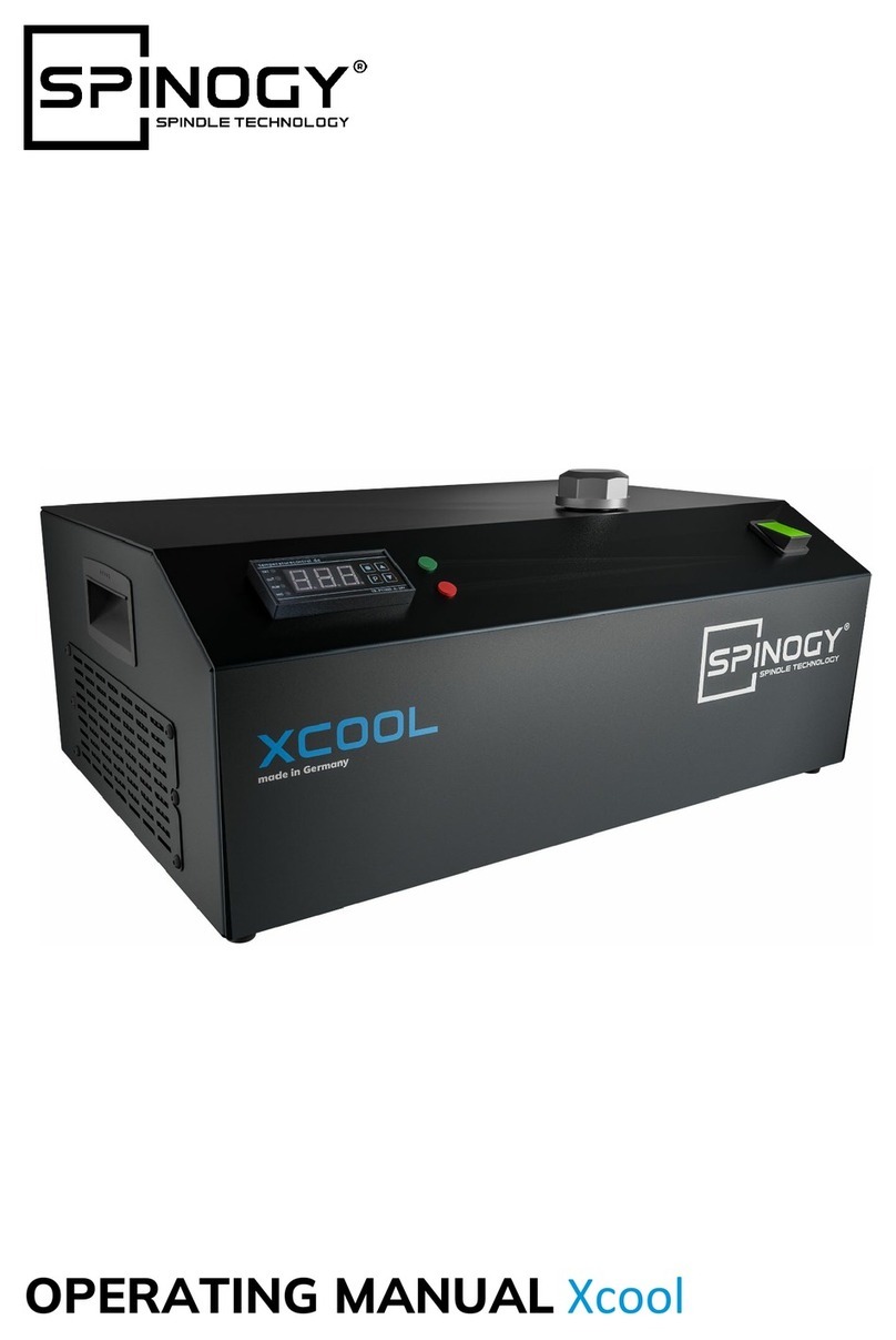
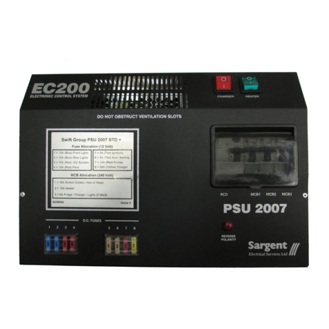
SPINOGY Xcontrol-E User manual

OPERATING MANUAL Xcontrol-E

spinogy.de

Index
Preamble
01
General remarks
6
01.1 Notice
01.2 Limitation of liability
01.3 Product name and type designation
01.4 Labeling of Xcontrol-E
01.5 Manufacturer details
01.6 Target group
01.7 Lifecycles of the machine
6
6
6
6
7
7
7
02
Safety instructions
8
02.1 Contractual use
02.2 Symbols and notes
02.3 Personnel requisition
02.4 Responsibilities and duties of the operator
02.5 Modifications and unauthorized changes
02.6 Special hazard warnings
8
8
8
10
10
10
03
Transport, packaging and storage
11
03.1 Transport
03.2 Packaging
03.3 Storage
11
11
11
04
Technical description
12
04.1 Configuration possibilities and technical data
04.2 Components
04.3 Dimensions
12
14
17
05
Installation
18
05.1 Transport damages check
05.2 Completeness check
05.3 Installation of Xcontrol-E
05.4 Electrical wiring
18
18
18
20
06
Commissioning
25
06.1 Power-on test
06.2 Commissioning for regular use
25
25
07
Maintenance
26

07.1 Maintenance
07.2 Spare parts
26
26
08
Disassembly and disposal
27
08.1 Disassembly
08.2 Disposal
27
27
09
Service and repair
28
09.1 Service and repair authorized users
28
10
Warranty
29
11
Declaration of installation
30

5
PREAMBLE
Preamble
Dear customer,
Thank you for choosing the spindle equipment Xcontrol-E from SPINOGY.
Along with this equipment for the spindle, you experience a perfectly aligned system.
The single components of the spindles are manufactured with our machines, assembled in Weiterstadt and
completed with high-quality purchased parts. So, we can monitor the complete manufacturing process and
always ensure a high quality. In order to keep the quality of this product for a long period, please carefully read
this operating manual.
SPINOGY is always working on further development of our products. Therefore, deviations may occur with the
spindle and the operating manual. We therefore ask you for your understanding, that no claims can be derived
from technical data, illustrations or descriptions.
During the development of this equipment, we have always taken care to involve the feedback of our customers.
Nevertheless, we always want to improve to be able to respond to requests even more specific. Therefore, we
are very grateful for your praise, constructive criticism and suggestions.
Please contact us for any request, questions or wishes about our products or your application case, we are glad
to help you. Just use our contact form on our website or contact us via E-Mail: [email protected]. Of course, we
are also available for a personal conversation.
We wish you a successful work.
Marcel Linke, Andreas Schleifer, Dominik Eschenbach and Marc Schmidt-Winterstein
Managing directors SPINOGY GmbH

6
01 GENERAL REMARKS
01General remarks
01.1 Notice
This operating manual contains important information about handling the product. It has to be read carefully
before use. The Xcontrol-E may only be put into operation if the operating manual was understood completely.
If there are obscurities, SPINOGY must be contacted. Please follow the instructions of this operating manual. This
operating manual must be available for the user at any time and must be replaced in case of loss or impracticality
immediately. The obligation to retain applies as long as someone is in possession of the product.
The content of this operating manual is checked for conformity with the described incomplete machine, but
deviations and mistakes cannot be excluded. Technical and content-related changes, errors and misprints are
reserved.
This operating manual is subject to the copyright law and may not be reproduced, copied or changed in any form,
neither all nor part, without the permission of the author. In case of contravention, there is a risk of criminal
prosecution. All rights reserved.
01.2 Limitation of liability
SPINOGY doesn’t assume liability for personal injuries, material damages, damages caused to the device and
consequential damages caused by failure to follow this operating manual, improper use of the device, repairs or
any other actions done by non-qualified workers (See chapter 2.3 personnel requisition) damages on this unit
occur or occurred by using unauthorized non-approved spare parts. Non-compliance of maintenance intervals
and maintenance specification of the manufacturer does also lead to limitation of liability. (Please see chapter 7
–maintenance) In addition, it is strictly prohibited to make any unauthorized modifications or technical changes
on the device.
01.3 Product name
This operating manual is created for the following product:
Product name:
Xcontrol-E, Xcontrol-E DIY
Compatible with
spindle:
XP001, XP002, XP003, XP004, XP005, XP006, XP007, XP008, XP021, XP022,
XP023, XP024 (as well as all configurations of these spindles)
01.4 Labeling of Xcontrol-P
X X X X X X
The Xcontrol-E is labeled with a six-digit serial number. The serial
number is located on the upper-left side of the door, pursuant to the
following picture.
Using this serial number, all necessary information about the
Xcontrol-E can be obtained from SPINOGY at any time.

7
01 GENERAL REMARKS
01.5 Manufacturer details
Name:
SPINOGY GmbH
Address:
Brunnenweg 17, 64331 Weiterstadt
E-Mail:
Phone:
+49 6150 / 970 960
Website:
spinogy.de
01.6 Target group
This operating manual is primarily aimed at the following staff:
• Installation staff
• Machine operators
• Maintenance staff
01.7 Lifecycles of the machine
The machine processes the following lifecycles:
• Transport
•Assembly
• Operation
• Maintenance
• Disassembly
• Disposal

8
02 SAFETY INSTRUCTIONS
02Safety instructions
02.1 Contractual use
The Xcontrol-E is to be considered as an incomplete machine for the installation into machine tools, covered by
the definition of a fixed industrial large tool. Seen in isolation, the Xcontrol-E cannot fulfill any function. The
installation has to be done by the manufacturer of the machine tool, as the required skills for professional
installation cannot be expected from end users. The Xcontrol-E is to be considered as equipment for a spindle
from SPINOGY and is only approved for this purpose.
02.2 Symbols and notes
The mentioned symbols in this operating manual shall obviously call the attention of the reader to potential
dangers. Those indications or warnings can never be seen as a replacement for correct accident prevention.
Warning of general hazard
Warning of dangerous electrical voltage
Note to avoid material damage
The following signal words are used:
SIGNAL WORD
MEANING
DANGER
Danger with a high risk-level that will result in death or serious injury in case of
non-observance
WARNING
Danger with a medium risk-level that will result in death or serious injury in case of
non-observance
CAUTION
Danger with a low risk-level that will result in minor or moderate injury in case of
non-observance
NOTE
Information that may lead to material damage in case of non-observance
02.3 Personnel requisition
Basic details
Only persons who can be expected to perform their work reliably are permitted as personnel. Persons who
have an affected capacity of reaction, e.g. through drugs, alcohol, or medication, are not permitted. Adhere to
the valid local regulations relating to age and profession when selecting staff.
WARNING: Improper use
Improper use of the product can lead to considerable personal injuries and material
damage. All activities may only be carried out by qualified and trained personnel. If the
personnel doesn't have the necessary expertise, the personnel is to be trained and
instructed.

9
02 SAFETY INSTRUCTIONS
Qualification
The tasks described in this operating manual represent different personal and professional requirements for
the qualifications of the people who are entrusted with these tasks. In this operating manual, the following
qualifications are therefore named and required for various fields of activity:
1. Professionals
Professionals are, due to their technical training, knowledge and experience and their knowledge of the relevant
standards and regulations, able to evaluate and carry out the given tasks. Furthermore, they are able to recognize
and avoid potential dangers independently.
2. Electricians
Electricians are, due to their technical training, knowledge and experience and their knowledge of the relevant
standards and regulations, able to evaluate and carry out the given tasks. Furthermore, they may recognize
and avoid potential dangers independently. These electrical engineering works are only allowed, however, to
be performed by electricians or under their direction and monitoring.
The technical requirements for electricians are:
• Technical education (electrical engineering)
• Knowledge and experience in the respective field of activity
• Knowledge of the relevant standards
• Evaluation of the work assigned to them
• Recognizing hazards
3. Instructed staff
Instructed staff are employees who can behave safely at their workplace. For this purpose, they must be
informed about the possible hazards resulting from the tasks assigned to them. In addition, they should
recognize the purpose of the occupational safety and health measures and assume personal responsibility for
their health-conscious behavior.
For this purpose, they must be informed by the operator about the tasks assigned to them and possible hazards
resulting from improper behavior. Corresponding effectiveness-checks by the operator are recommended.
Note: Staff must be regularly and sufficiently instructed by the operator. Further details are regulated in the
national occupational safety laws and regulations. For better traceability, the execution of the instruction must
be recorded.
WARNING: Unauthorized staff
Unauthorized staff is unaware of the hazards in their work area. Failure to comply with the
personnel requisition can result in serious injury or even death.
Unauthorized staff
Any person who:
• has not read this operating manual, has not read it completely or has not clearly understood it
• does not meet the qualification requirements for working with Xcontrol-E
• has not received instructions from the operator for working with Xcontrol-E
is considered an unauthorized person.
The following points must therefore be observed in any case:
• Keep unauthorized persons away from the danger and work area
• In case of doubt, talk to persons and direct them away from the danger and work area
• Interrupt the work as long as unauthorized persons are in the danger and work area
• Deny access to unauthorized people

10
02 SAFETY INSTRUCTIONS
02.4 Responsibilities and duties of the operator
The operator himself is assumed to have the necessary qualifications and special expertise in handling machine
tools and systems. If the operator does not carry out the necessary work himself, appropriate personnel must be
called in for the professional installation, commissioning, maintenance and repair, dismantling/ decommissioning/
disposal!
In addition to the safety instructions in this manual, the country-specific safety measures, occupational health
and safety measures and environmental protection regulations etc. valid for the application range of the machine
must be observed.
Furthermore, the operator is responsible for the following points:
• Ensuring that the Xcontrol-E is always in a technically perfect condition
• Compliance with maintenance intervals
• Creating of operating instructions
• Creating of hazard assessments
• Training and instruction of authorized staff at regular intervals
• Ensuring that authorized persons using the Xcontrol-E, have carefully read and understood the operating
manual
• Equipping staff with the appropriate protective equipment
02.5 Modifications and unauthorized changes
Modifications and unauthorized changes at the spindle by the operator are only permitted after consulting
SPINOGY. If unauthorized modifications are made, the issued CE declaration of conformity loses its validity and
the operator legally becomes the machine manufacturer.
02.6 Special hazard warnings
DANGER: Electrical voltage
There is a risk of electric shock, which can lead to serious injury or death. Before working on
the Xcontrol-E, switch it off and disconnect it from the electrical network!

11
03 TRANSPORT, PACKAGING AND STORAGE
03Transport, packaging and
storage
03.1 Transport
Xcontrol-E is to be transported in a stable packaging with sufficient padding. During the transport, it must be
taken care to avoid strong vibrations or shocks, as otherwise damages may occur.
Transport may only be carried out by qualified transport companies or qualified personnel.
The corresponding dimensions and weight specifications of Xcontrol-E can be found in the technical data in
chapter 4.
03.2 Packaging
The packaging is intended to protect Xcontrol-E until assembly from transport damages and other external
influences such as corrosion. The packaging should therefore only be removed shortly before assembly. In
addition, the packaging should be kept, if possible, to protect Xcontrol-E in case of storage or to wrap it
properly in case of return.
All packaging materials must be disposed at the appropriate collection points.
03.3 Storage
The following precautions must be arranged in case of storing Xcontrol-E:
• Xcontrol-E must be stored protected against dust, moisture and other environmental influences
• Mechanical vibrations of Xcontrol-E must be avoided
• The door of Xcontrol-E must be closed
• All openings of Xcontrol-E must be closed
• The following conditions for storage must be observed:
o Temperature storage location: +10 to 45 °C
o Relative humidity <40%
o Do not store outdoor

12
04 TECHNICAL DESCRIPTION
04Technical description
04.1 Configuration possibilities and technical data
The Xcontrol-E is designed for the operation of all SPINOGY spindles and is used for electrical control. It is a
plug and play system that includes all electrical components necessary for the operation of a spindle. In
addition, the Xcontrol-E can be configured according to your own requirements. A useful basic configuration is
provided by SPINOGY and can be found in the following chart.
Equipment no.:
XM039/XM044
XM040/XM045
XM042/XM046
XM043/XM047
Designation
F-M/F-M-DIY
L-M/L-M-DIY
F-ATC/F-ATC-DIY
L-ATC/L-ATC-DIY
Type of spindle
manual or semi-automatic
automatic
Cooling method spindle
liquid-cooled
air-cooled
liquid-cooled
air-cooled
Frequency inverter
2,2 kW SVC 230 V
Power supply [V]
230 (1-phase)
Braking resistor
70 600 W / 10 s, 2% ED
Outputs (customer site)
16 (depending on type of spindle and equipment, not all necessary)
Inputs (customer site)
11 (depending on type of spindle and equipment, not all necessary)
Emergency stop circuit
2-pole with switch-off delay time and manual reset
Electrical cabinet
housing
Proper emc-housing
Protective class
IP20
Weight [kg]
16
Cable length motor
connection (orange) [m]
5
Cable length
sensor connection
(green) [m]
-
5
Cable length PE –
Protective earth
(green/yellow) [m]
5
Cable length
power supply [m]
5
Frequency inverter
programming
programmed
Communication ports
-
Further interfaces
Integration of Xcontrol-P and Xcool

13
04 TECHNICAL DESCRIPTION
There are the following configuration possibilities of the Xcontrol-E:
Frequency inverter
Power [kW]
Voltage [V]
Type
Braking resistor
1,5
230 (1-phase)
SVC
70 600 W / 10 s, 2% ED
1,5
230 (1-phase)
HF
70 600 W / 10 s, 2% ED
1,5
400 (3-phase)
SVC
200 600 W / 10 s, 2% ED
1,5
400 (3-phase)
HF
200 600 W / 10 s, 2% ED
2,2
230 (1-phase)
SVC
70 600 W / 10 s, 2% ED
2,2
230 (1-phase)
HF
70 600 W / 10 s, 2% ED
2,2
400 (3-phase)
SVC
200 600 W / 10 s, 2% ED
2,2
400 (3-phase)
HF
200 600 W / 10 s, 2% ED
Cable length
Motor connection [m]
Sensor connection [m]
PE-Protective earth
[m]
Network connection
[m]
Without
Without
2
Without
2
2
5
5
5
5
8
8
8
11
11
14
14
Further configuration possibilities
Communication ports
Programming frequency inverter
Kundenspezifisch
Without
Without
Without
RJ45
Already programmed
Special configurations possible after
consulting SPINOGY
USB
Profibus
Profinet

14
04 TECHNICAL DESCRIPTION
04.2 Components
The following picture shows the main components of the Xcontrol-E.
View door

15
04 TECHNICAL DESCRIPTION
View inside
View connection ports

16
04 TECHNICAL DESCRIPTION
Frequency inverter
Motor power [kW]
1,5
2,2
1,5
2,2
Nominal input voltage [V]
1-phase: 200 V –15 % to 240 V +10
%, 50/60 Hz ±5 %
3-phase: 380 V –15 % to 480 V +10
%, 50/60 Hz ±5 %
Nominal output voltage [V]
3-phase: 200 bis 240 V
3-phase: 380 to 480 V
Nominal output current [A]
8,0
11,0
4,8
5,5
Version
SVC oder HF
Braking resistor (10 % ED, max. 10s)
Voltage [V]
230 (1-phase)
400 (3-phase)
Motor power [kW]
1,5 or 2,2
1,5 or 2,2
Resistance []
70
200
Braking moment [%]
200
190
Power supply unit
Power [W]
60
Output voltage [V]
24
Nominal current [A]
2,5
Ambient temperature [°C]
-40 –70 °C
Safety relay
Power [W]
Maximum 4
Supply voltage [V DC]
24
Direct switching outputs
2 normally open
Output with switch-off delay
2 normally open
Maximum turn-off delay time [s]
30
Ambient temperature [°C]
-10 to 55
Relay
Supply voltages [V DC]
24
Maximum switched voltage [V DC]
250
Maximum switched current [A]
8
Contact type
2 changeovers
Ambient temperature [°C]
-40 to 70
Circuit braker
Operating voltage [V AC]
230
Type
1-pole B16 A
Nominal current [A]
16
Ambient temperature [°C]
-25 to 55
Main switch
Maximum switched voltage [V AC]
690
Maximum switched current [A]
20
Ambient temperature [°C]
-25 to 50
Function
Locking
Feature
Lockable in 0-position

17
04 TECHNICAL DESCRIPTION
Emergency stop
Maximum switching voltage [V AC]
240
Maximum switching current [A]
6
Contact type
2x Normally closed
Ambient temperature [°C]
-25 to 55
Function
Locking
Release type
Rotary release
04.3 Dimensions

18
05 INSTALLATION
05Installation
05.1 Transport damages check
The entire delivery must be checked for transport damage after acceptance. In case of external damage to the
packaging, this must be documented. After unpacking the SPINOGY X22 and the additional scope of delivery,
the products must be checked directly for transport damage. In case of damage to the products, this must be
documented. Despite the greatest care in packaging and shipping our products, transport damage may occur as
a result of improper handling or force majeure in transit. Defective or damaged products must not be put into
operation. The products must always be used in perfect condition.
If transport damage is detected or if there are any questions, SPINOGY must be contacted immediately.
05.2 Completeness check
The content of the consignment must be checked for completeness. If any parts are missing, contact SPINOGY.
Scope of delivery:
• Xcontrol-E
• Key for the door of the Xcontrol-E
05.3 Installation of the Xcontrol-E
The installation of the Xcontrol-E may only be carried out by qualified staff. During all work, the locally applicable
occupational safety and accident prevention regulations as well as internal company regulations must be
observed and complied with. Suitable tools must be used for the installation.
WARNING: Unauthorized staff
Unauthorized employees are not aware of the hazards in the respective work area. Failure
to comply with the personnel requisition can result in serious injury or even death.
WARNING: Falling parts
During installation, components may fall, resulting in serious injury and property damage. It
is recommended to work at least in pairs and to wear protective equipment and use
appropriate tools.

19
05 INSTALLATION
The Xcontrol-E is to be installed in the following steps:
01. Mount the Xcontrol-E on the machine or on the wall.
02. Connect the separate protective earth conductor.
03. Connect the motor connection cable (orange) to the spindle.
04. Connect the sensor connection cable (green) to the spindle (only for spindles with sensors)
05. Connect the control cable to the terminals (not included in the scope of delivery).
06. Optionally: Connect an external emergency stop to the terminals (e.g. door safety switch).
07. Optionally: Connect the Xcontrol-P signal cable to the terminals.
08. Optionally: Connect the Xcool signal cable to the terminals.
09. Check, whether the main switch is set to 0/Off.
10. Check whether the circuit braker is set to 0/Off.
11. Check whether the emergency stop switch is activated.
12. Connect the power cord (directly, without power supply plug).
13. The circuit braker needs to be set to 1/On again.
The Xcontrol-E must be mounted vertically, the connection cables pointing downwards, as the heat convection
of the frequency inverter is vertical. In addition, the Xcontrol-E must be suspended with sufficient distance to
surrounding components so that the intake area of the fan and the air outlet remain free.

20
05 INSTALLATION
05.4 Electrical wiring
Connecting the Xcontrol-E must be done by a qualified electrician. In addition to the explanations in this chapter,
the electrical circuit diagram of the Xcontrol-E must also be consulted.
DANGER: Electrical voltage
There is a risk of electric shock, which can cause serious injury or death. Before working on
the Xcontrol-E, switch it off and disconnect it from the electrical network, and make sure
that the capacitors of the frequency inverter are discharged.
All connections, leading out of the Xcontrol-E are connected internally to the terminal block X1. The terminals are
assigned as follows:
Terminal
L1 X1:1 F1:2 Circuit braker
N X1:2 Q1:4 Main switch
PE X1:3 PE-Neutral point Neutral point
- X1:4 Q1:1 Main switch
- X1:5 G1:L Power supply unit
- X1:6 V1:L Input - power supply unit
- X1:7 M1:1 Fan
- X1:8 Q1:3 Main switch
- X1:9 M1:2 Fan
- X1:10 G1:N Power supply unit
- X1:11 V1:N Input - power supply unit
L1 X1:12 U1:U/T1 Frequency inverter
L2 X1:13 U1:V/T2 Frequency inverter
L3 X1:14 U1:W/T3 Frequency inverter
PE X1:15 PE-Neutral point PE-Neutral point
PE X1:16
PTC + X1:17 U1:5 Frequency inverter
PTC - X1:18 U1:L Frequency inverter
Fan 0 V X1:19 X1:53 0 V
Fan 24 V X1:20 X1:46 24 V
Pin1 0 V X1:21 X1:48 0 V
Pin2 24 V X1:22 X1:42 24 V
Clamped without tool S1 X1:23 Pin 3
Clamped with tool S2 X1:24 Pin 4
Ejection position (piston) S3 X1:25 Pin 5
PT100 bearing front V+ X1:26 Pin 6
PT100 bearing front V- X1:27 Pin 7
PT100 bearing back H+ X1:28 Pin 8
PT100 bearing back H- X1:29 Pin 9
Encoder PZ X1:30 Pin 10
Encoder NZ X1:31 Pin 11
Signal rotational speed oder Encoder PA X1:32 Pin 12
Encoder NA X1:33 Pin 13
Encoder PB X1:34 Pin 14
Encoder NB X1:35 Pin 15
Encoder Vcc (5 V) X1:36 Pin 16
-X1:37 PE
Optional: 24V from X1:44with switch X1:38 Optional: Xcontrol-P valve (cable Pin-1) Optional: Xcontrol-P
0 bis 10 V (spindle speed) X1:39 U1:O Frequency inverter
0 V (spindle rotational speed) X1:40 (0V) (U1:L) Frequency inverter
0 V start signal spindel X1:41 K1:A2 Relay (start/stop)
Relay output to control X1:42 A1:24 Safety relay U1:AL1 from FU
Relays output to control X1:43 U1:AL0 Frequency inverter
Control cable
(provided by the customer)
Optional:24 V for Xcontrol-P to X1:38 X1:44 G1:V1+ Power supply unit 24 V
- X1:45 A1:T33 Safety relay
- X1:46 X1:20 Fan spindle 24 V
- X1:47 A1:37 Safety relay 24 V U1:3/GS1
- X1:48 X1:21 Sensor connection cable 24 V
- X1:49 A1:47 Safety relay 24 V U1:4/GS2
- X1:50 K1:A1 Relay 24 V
- X1:51 A1:A1 Saftey relay 24 V
Control cable
(provided by the customer)
Optional: Xcontrol-P valve (cable Pin-2) X1:52 G1:V1- Power supply unit 0 V
- X1:53 X1:19 Fan spindel 0 V
- X1:54 X1:22 Sensor connection cable 0 V
Control cable
(provided by the customer)
Potential machine control (0 V) X1:55 X1:40 machine control 0 V
- - X1:56 A1:A2 Safety relay 0 V – power supply
X1:57 S1:2
X1:58 Optional: Xcontrol-P pressure switch (cable Pin-3)
Optional: Xcontrol-P pressure switch (cable Pin-4) X1:59 A1:T12
X1:60 S1:4
X1:61 Optional: Xcool Pin-1
Optional: Xcool Pin-2 X1:62 A1:T22
Sensor connection cable
-
-
Lower row
Upper row
Power supply
-
Motor connection cable
Control cable
(provided by the customer)
Sensor connection cable
External emergency stop
(remove bridge)
Ext. Emergency stop (channel 1)
Emergency stop (channel 1)
Ext. Emergency stop (channel 2)
Emergency stop (channel 2)
This manual suits for next models
1
Table of contents
Other SPINOGY Control System manuals
Popular Control System manuals by other brands
Quilo
Quilo QK-CT219500 Instructions for installation, use and maintenance
Parker
Parker BA Series Installation & Disassembly
Beninca
Beninca VE.650 Operating instructions and spare parts catalogue
Lennox
Lennox Harmony III Homeowner's manual

Yetter
Yetter AIR ADJUST 2940 Operator's manual

Rotel
Rotel RR-700 owner's manual
