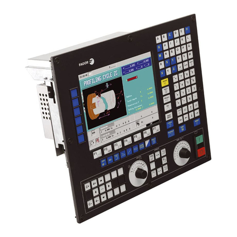
Fagor 101 User manual

The information described in this manual may be subject to variations due to
technicalmodifications.
FAGOR AUTOMATION, S. Coop. Ltda. reserves the right to modify the
contentsofthismanualwithoutpriornotice.

INDEX
Section Page
Comparison table for FAGOR CNC models: 101/101S/102/102S ...................................... ix
New Features and Modifications .......................................................................................... xiii
INTRODUCTION
Safety Conditions................................................................................................................ 3
Material Returning Terms .................................................................................................. 6
Fagor Documentation for the 101/101S/102/102S CNC................................................. 7
Manual Contents ................................................................................................................. 8
Chapter1 PERIPHERALS
1.1 Front panel description......................................................................................................... 1
1.2 Peripheral mode .................................................................................................................... 2
1.2.1 "1-Output" option. CNC --> peripheral ................................................................................ 3
1.2.2 "2-Input" option. Peripheral --> CNC ................................................................................... 4
Chapter2 AUXMODE
2.1 System Input/Output test ...................................................................................................... 2
2.2 Machine parameters.............................................................................................................. 5
2.2.1 Editing machine parameters ................................................................................................. 5
2.3 Tool table or zero offset table............................................................................................... 7
Chapter3 JOGMODE
3.1 Jogging the axes ................................................................................................................... 1
3.2 Automatic positioning ......................................................................................................... 5
3.3 Zero setting or coordinate preset .......................................................................................... 5
3.4 Machine Reference (Home) search ....................................................................................... 6
3.4.1 Considerations about the machine reference zero (home).................................................... 7
3.5 Operation of the CNC as a DRO ........................................................................................... 7

Section Page
Chapter4 PROGRAMEDITING
4.1 Editing mode ........................................................................................................................ 1
4.1.1 Displaying block contents ................................................................................................... 3
4.1.2 Program editing .................................................................................................................... 4
4.1.3 Deleting Block contents....................................................................................................... 6
4.1.4 Deleting the whole program memory ................................................................................... 6
4.1.5 Modifying block contents.................................................................................................... 7
4.1.6 Inserting a new program block ............................................................................................. 9
4.1.7 Eliminating empty blocks (memory compression)............................................................... 9
4.2 Teach-in editing ................................................................................................................... 10
4.3 Play-back editing ................................................................................................................. 11
4.3.1 Reading points in Play-Back Mode ..................................................................................... 12
Chapter5 PROGRAMEXECUTION
5.1 Program execution................................................................................................................ 1
5.2 Program interruption ............................................................................................................ 2
5.3 Display modes ...................................................................................................................... 3
5.4 Display of the arithmetic parameters .................................................................................... 6
5.5 Change of operating mode ................................................................................................... 6
Chapter 6 PROGRAMMING
6.1 Programmingformat ............................................................................................................. 1
6.1.1 Preparatory G functions ........................................................................................................ 2
6.2 Basic concepts ...................................................................................................................... 3
6.2.1 Block number and conditional block (block skip) .............................................................. 3
6.2.2 Metric or inch programming (G70/G71) .............................................................................. 3
6.2.3 Absolute / incremental programming (G90/G91)................................................................. 3
6.3 Reference systems................................................................................................................. 5
6.3.1 Reference points ................................................................................................................... 5
6.3.2 Machine Reference (home) search (G74) ............................................................................. 6
6.3.3 Coordinate preset and zero offsets........................................................................................ 7
6.3.3.1 Coordinate preset (G92) ....................................................................................................... 7
6.3.3.2 Zero offset loading (G51....G60) ........................................................................................... 8
6.3.3.3 Zero offset selection (T1 ... T10)........................................................................................... 8
6.4 Complementary functions .................................................................................................... 9
6.4.1 Axisfeedrate "F" ................................................................................................................... 9
6.4.2 Spindle speed "S" ................................................................................................................. 9
6.4.3 Tool number "T" ................................................................................................................... 10
6.4.4 Zerooffset"T"....................................................................................................................... 10
6.4.5 Miscellaneous /auxiliary) "M" function............................................................................... 10
6.5 Path control .......................................................................................................................... 12
6.5.1 Rapid positioning (G00) ...................................................................................................... 12
6.5.2 Linear interpolation (G01) ................................................................................................... 13
6.5.3 Circular interpolation (G02, G03) ........................................................................................ 14
6.5.4 Synchronization (G33) ......................................................................................................... 16
6.5.5 Axis X as an infinite slave of another axis (G34) ................................................................. 18
6.5.5.1 Automatic pass compensation.............................................................................................. 20
Section Page
6.6 Additional preparatory functions ......................................................................................... 21
6.6.1 Dwell(G04) .......................................................................................................................... 21
6.6.2 Increment part counter (G45)................................................................................................ 21
6.6.3 Round corner (G05) and square corner (G07)....................................................................... 22
6.7 Special functions .................................................................................................................. 23
6.7.1 Feedback inhibit (G47, G56) ................................................................................................ 23
6.7.2 G47, G48 as opening of the axis loop .................................................................................. 24
6.7.3 The feedrate "F" is not affected by "P18" (G61, G62)........................................................... 25
6.7.4 Acceleration ramp modification (G93)................................................................................. 25
6.8 Other functions ..................................................................................................................... 26
6.8.1 Batch programming (G81).................................................................................................... 26
6.8.2 Probing (G75) ....................................................................................................................... 28
6.8.3 Rigid tapping (G84, G80)..................................................................................................... 29
6.8.4 Loading the punch sizes (G60)............................................................................................. 32
6.9 Parametricprogramming ...................................................................................................... 33
6.9.1 Assignments ......................................................................................................................... 33
6.9.2 Operations ............................................................................................................................ 34
6.9.3 Access to the arithmetic parameter table .............................................................................. 37
6.9.4 Unconditional jump function (G25)..................................................................................... 39
6.9.5 Conditional jump functions (G26, G27, G28, G29) ............................................................. 41
ERRORCODES

GENERAL CARACTERISTICS
101 101S 102 102S
Feedback inputs Connector A1 (X axis) x x x x
Connector A2 (Y axis) x x x
x5 multiplier circuit for sine-wave signals x x x
Feedback correction factor x x x x
Analog outputs X axis x x x x
Y axis x x
Spindle (S) x x x x
Axes X axis x x x x
X + Y axis x x
X axis + electronic handwheel x x x
Axes X + Y + auxiliary handwheel x x x
Double feedback for X axis x
Axis control Closed Loop x x x x
Open Loop x x
Rigid Tapping x
Interface with external
devices External operator panel "JOG 100" x x
RS232C Interface x x x
Fagor Local Area Network (LAN) x x x
DNC 100 x x
Operating options Overtemperature alarm x x x
Operation in radius or diameter x x x
Operation with a probe x x x
Zero offsets x x x
Tool length compensation x x x
Acceleration / deceleration x x x x

INPUTS AND OUTPUTS
101 101S 102 102S
INPUTS X axis home switch x x x x
Y axis home switch x x x
External emergency stop x x x x
Feedhold x x x x
External Cycle Start x x x x
External Cycle Stop x x x x
Conditional input (block skip) x x x x
Manual input (DRO mode) x x x x
External Reset (initial CNC conditions) x x x x
2 inputs as Handwheel multiplying factor JOG100 xJOG100
2 inputs for Feedrate override JOG100 xJOG100
5 inputs for parametric programming x x x
2 inputs for handling the auxiliary handwheel x x x
OUTPUTS 8 outputs for M, S or T in BCD or decoded x x x x
M Strobe x x x x
S Strobe x x x
T Strobe x x x
JOG mode selected at the CNC x x x x
Automatic mode selected at the CNC x x x
Internal CNC emergency x x x x
X axis brake x x x x
Y axis brake x x
X axis in position x x x x
Y axis in position x x
X axis Fast (Non-servocontrolled open loop) xJOG 100 xJOG 100
X axis Slow (Non-servocontrolled open loop) xJOG 100 xJOG 100
X direction (Non-servocontrolled open loop) xJOG 100 xJOG 100
Y axis Fast (Non-servocontrolled open loop) JOG 100 xJOG 100
Y axis Slow (Non-servocontrolled open loop) x
Y direction (Non-servocontrolled open loop) x

PROGRAMMING
101 101S 102 102S
Number of blocks 900 900 900 900
Conditional blocks (block skip) x x x x
Parts counter x x x x
Arithmetic programming x x x
Arithmetic parameters 100 100 100
PROGRAMMI
FUNCTIONS G00 Rapid positioning x x x x
G01 Linear interpolation x x x x
G02 Clockwise circular interpolation x x
G03 Counter-clockwise circular interpolation x x
G04 Dwell x x x x
G05 Round corner x x x x
G07 Square corner x x x x
G25 Unconditional jump x x x x
G26 Jump if zero x x x
G27 Jump if not zero x x x
G28 Jump if less than zero x x x
G29 Jump if equal or greater than zero x x x
G33 Synchronization x
G45 Increment part-counter's count x x x x
G47 Pulse inhibit x x x
G48 Cancel function G47 x x x
G51 to G60 Load zero offset x x x
G61 F not affected by "P18" x x x x
G62 Cancel function G61 x x x x
G70 Inch programming x x x x
G71 Metric programming x x x x
G74 Machine Reference (home) search x x x x
G75 Probing x x x
G81 Batch programming x x
G84, G80 Rigid tapping x
G90 Absolute coordinate programming x x x x
G91 Incremental coordinate programming x x x x
G92 Coordinate presetting x x x x
G93 Modification of acceleration ramp x x x

NEW FEATURES
AND
MODIFICATIONS
Date: March 1997 SoftwareVersion: 2.1 and newer
FEATURE AFFECTED MANUAL AND SECTION
Synchronizationof movements(G33) OperatingManual Section 6.5.4
Axis X as infinite slave of another axis (G34) InstallationManual Section 5.5
OperatingManual Section 6.5.5
G47, G48 as axis loop opener InstallationManual Section 5.7
OperatingManual Section 6.7.2
G75 special function InstallationManual Section 5.6
Travellimit control taking intoaccountthe InstallationManual Section 5.8
the punch radius OperatingManual Section 6.8.4
SelectionoftheArithmeticalParameters InstallationManual Section 3.7
which are required for display. OperatingManual Section 6.9.3
Play-Back, as reading points. InstallationManual Section 3.6
OperatingManual Section 4.3.1
ParametricalprogrammingtakestheS Installation Manual Sect. 5.1 and 6.7
signintoaccount
The axes can be denominated Y, C InstallationManual Section 3.4
Auxiliary Handwheel handling by Installation Manual Sect. 1.7, 3.4 and
means of 2 digital inputs OperatingManual Section 3.1
Braking Control in open loop InstallationManual Section 4.4.2
Reading/Writingofmachineparameters
from the DNC100
ErroreliminationbyexternalReset.

Introduction - 3
SAFETYCONDITIONS
Readthefollowingsafetymeasuresinordertopreventdamagetopersonnel, tothis
product and to those products connected to it.
This unit must only be repaired by personnel authorized by Fagor Automation.
FagorAutomationshallnotbeheldresponsibleforanyphysicalormaterialdamage
derivedfromtheviolationofthese basic safety regulations.
Precautions against personal damage
Use proper Mains AC power cables
To avoid risks, use only the Mains AC cables recommended for this unit.
Avoidelectricaloverloads
Inordertoavoidelectricaldischargesandfirehazards,donotapplyelectricalvoltage
outside the range selected on the rear panel of the Central Unit.
Groundconnection
Inordertoavoidelectricaldischarges,connectthegroundterminalsofallthemodules
tothemaingroundterminal.Beforeconnectingtheinputsandoutputsofthisunit,make
sure that all the grounding connections are properly made.
Before powering the unit up, make sure that it is connected to ground
Inordertoavoidelectricaldischarges,makesurethatallthegroundingconnectionsare
properlymade.
Do not work in humid environments
In order to avoid electrical discharges, always work under 90% of relative humidity
(non-condensing) and 45º C (113º F).
Do not work in explosive environments
In order to avoid risks, damage, do not work in explosive environments.
Precautions against product damage
Workingenvironment
ThisunitisreadytobeusedinIndustrialEnvironmentscomplyingwiththedirectives
andregulations effective in the European Community
Fagor Automation shall not be held responsible for any damage suffered or caused
wheninstalledinother environments(residential orhomes).
Install the unit in the right place
Itisrecommended,wheneverpossible,toinstaltheCNCawayfromcoolants,chemical
product, blows, etc. that could damage it.
This unit complies with the European directives on electromagnetic compatibility.
Nevertheless, it is recommended to keep it away from sources of electromagnetic
disturbance such as.

Introduction - 4
-Powerful loads connected to the same AC power line as this equipment.
-Nearbyportabletransmitters(Radio-telephones,Hamradiotransmitters).
-Nearby radio / TC transmitters.
-Nearby arc welding machines
-Nearby High Voltage power lines
-Etc.
Enclosures
Themanufacturerisresponsibleofassuringthattheenclosureinvolvingtheequipment
meetsallthe currently effective directives of theEuropeanCommunity.
Avoid disturbances coming from the machine tool
The machine-tool must have all the interference generating elements (relay coils,
contactors,motors,etc.)uncoupled.
Use the proper power supply
Use an external regulated 24 Vdc power supply for the inputs and outputs.
Grounding of the power supply
Thezerovoltpointoftheexternalpowersupplymustbeconnectedtothemainground
point of the machine.
Analog inputs and outputs connection
Itisrecommendedtoconnectthemusingshieldedcablesandconnectingtheirshields
(mesh) to the corresponding pin (See chapter 2).
Ambientconditions
The working temperature must be between +5° C and +45° C (41ºF and 113º F)
The storage temperature must be between -25° C and 70° C. (-13º F and 158º F)
Monitorenclosure
AssurethattheMonitorisinstalledatthedistancesindicatedinchapter1fromthewalls
of the enclosure.
Use a DC fan to improve enclosure ventilation.
Main AC Power Switch
This switch must be easy to access and at a distance between 0.7 m (27.5 inches) and
1.7 m (5.6 ft) off the floor.
Protections of the unit itself
It carries two fast fuses of 3.15 Amp./ 250V. to protect the mains AC input.
Allthedigitalinputsandoutputshavegalvanicisolationviaoptocouplersbetweenthe
CNC circuitry and the outside.
Theyareprotectedbyanexternalfastfuse(F)of3.15Amp./250V.againstovervoltage
and reverse connection of the power supply.
Thetypeoffusedependsonthetypeofmonitor.Seetheidentificationlabeloftheunit.

Introduction - 5
Precautions during repair
Do not manipulate the inside of the unit
OnlypersonnelauthorizedbyFagorAutomationmaymanipulatethe
insideof this unit.
DonotmanipulatetheconnectorswiththeunitconnectedtoACpower.
Before manipulating the connectors (inputs/outputs, feedback, etc.)
make sure that the unit is not connected to AC power.
Safety symbols
Symbols which may appear on the manual
WARNING. symbol
Ithasanassociatedtextindicatingthoseactionsoroperationsmayhurtpeople
or damage products.
Symbols that may be carried on the product
WARNING. symbol
Ithasanassociatedtextindicatingthoseactionsoroperationsmayhurtpeople
or damage products.
"ElectricalShock"symbol
Itindicates that point may be under electrical voltage
"Ground Protection" symbol
It indicates that point must be connected to the main ground point of the
machine as protection for people and units.

Introduction - 6
MATERIALRETURNINGTERMS
When returning the CNC, pack it in its original package and with its original packaging
material.If not available, pack it as follows:
1.- Getacardboardboxwhosethreeinsidedimensionsareatleast15cm(6inches) larger
thanthoseoftheunit.Thecardboardbeingusedtomaketheboxmusthavearesistance
of 170 Kg (375 lb.).
2.- When sending it to a Fagor Automation office for repair, attach a label indicating the
owner of the unit, person to contact, type of unit, serial number, symptom and a brief
descriptionofthe problem.
3.- Wrap the unit in a polyethylene roll or similar material to protect it.
When sending the monitor, especially protect the CRT glass.
4.- Pad the unit inside the cardboard box with poly-utherane foam on all sides.
5.- Seal the cardboard box with packing tape or industrial staples.

Introduction - 7
FAGOR DOCUMENTATION
FOR THE 101/101S / 102/102S CNC
101/101S / 102/102S CNC OEM Manual
Is directed to the machine builder or person in charge of installing and starting
up the CNC.
It has the Installation manual inside. Sometimes, it may contain an additional
manual describing New Software Features recently implemented.
101/101S / 102/102S CNC USER Manual
Is directed to the end user or CNC operator.
It contains the Operating manual.
Sometimes, it may contain an additional manual describing New Software
Features recently implemented.

Introduction - 8
MANUAL CONTENTS
The installation manual consists of the following sections:
Index
Comparative Table for Fagor 101/101S / 102/102S CNC models
Introduction Safety Conditions
Shipping conditions
Fagor documents for the 101/101S / 102/102S CNC
Manual Contents
Chapter 1 Peripherials
Chapter 2 Aux mode
Chapter 3 Jog mode
Chapter 4 Program editing
Chapter 5 Program execution
Chapter 6 Programming
ErrorCodes

PERIPHERALS 1
Chapter: 1 Section: Page
1. PERIPHERALS
1.1 FRONT PANEL DESCRIPTION
1.- These 2 windows show the internal CNC information.
2.- Keys used to select any of the operating modes. When the lamp is lit, it indicates that
thecorresponding operating mode iscurrentlyselected.
Peripheralmode.
Aux Mode
JOG mode
Play-Backmode
Editingmode
Single-blockmode
Automaticmode
3.- Keystomanipulateinternaldata,setuptables,parameters,editprograms,presetvalues,
etc.
4.- The key executes the program. The key interrupts the execution of
the program y and the keyresetstheCNCtoinitialconditionsassumingthe
defaultvaluesassigned to the machine parameters.
FRONT PANEL
DESCRIPTION

PERIPHERALS2
Section:Chapter: 1
Page
1.2 PERIPHERAL MODE
In order to access this operating mode, machine parameter "P100(1)" must be set to "0"
indicating that the DNC feature is not available.
Withthisoperatingmode,itispossibletotransferpart-programs,machine-parametersand
thetooltableout toa peripheraldevice (cassettereaderFAGORLS80,PC,terminal,etc.)
through the RS232C serial line
To do this, the machine parameters corresponding to the RS232C serial line must be set
accordingly:
P70 Communicationsspeed(baudrate)inbaud.
P59(7) Number of data bits.
P59(5) Parity
P59(6) Even or Odd parity
P59(8) Number of stop bits
Bear in mind that the CNC must be off when connecting or disconnecting any peripheral
device to it.
To access the peripheral mode, press the key.
The CNC will show the following information:
The upper display indicates that the RS232C line is
selected.
The lower display shows the two possible options:
0 -> Input, 1 -> Output.
Select the "0-Input" option to receive information from a peripheral device and the "1-
Output" to send information out to a peripheral device
PERIPHERAL MODE

PERIPHERALS 3
Chapter: 1 Section: Page
1.2.1 "1-OUTPUT" OPTION. CNC --> PERIPHERAL
This option must be selected once the peripheral device has been set ready to receive.
The lower CNC display will show the letter "N".
Depending on what has to be transmitted, proceed as follows:
a) To send the machine parameter table and tool table or zero offset table.
Press the following keystroke sequence: [8] [9] [9] [A-]
The transmitted data is illegible and must be used as a back-up copy either to be sent
back to the CNC later on or to another similar CNC.
b) To send the whole content of the part-program memory, that is from N000 to block
N899, out to a peripheral:
Press:[A+]
c) To transmit the contents of the part-program memory starting at a particular block
number:
Press the number of the first block to be transmitted and, then, press [A+].
For example, The keystroke sequence: [1] [0] [0][A+] will send blocks N100 and all
the following ones out to the peripheral.
d) Totransmit a particular set of blocksof thepart-program memory:
Indicatethefirstandlastblockstobetransmittedseparatedbyaperiodandpress[A+].
For example, the keystroke sequence: [2] [0] [0] [.] [2] [2] [0] [A+] will send all the
blocks between N200 and N220 (both included).
The CNC format to send each block consists of 3 digits indicating the block number, the
blockcontentsand theCarriageReturn(RT)and LineFeed(LF)charactersindicatingthe
end of the block.
Once all the blocks have been sent, the CNC sends the ESCAPE character indicating the
endoftransmission.
Example: 012 G01.91 X130 Y-56.3 F200 RT LF
013 X17.9 M6 RT LF
-
-
369 M30 RT LF ESC
The transmission can be aborted at any time by pressing [CL].
PERIPHERAL MODE
This manual suits for next models
3
Table of contents
Other Fagor Control System manuals

Fagor
Fagor CNC 8070 Quick guide

Fagor
Fagor CNC 8060 LASER User manual

Fagor
Fagor CNC 8060 User manual

Fagor
Fagor CNC 8060 User manual

Fagor
Fagor CNC 8055 TC User manual

Fagor
Fagor CNC8 070 Administrator guide

Fagor
Fagor 8055 M Owner's manual

Fagor
Fagor CNC 8060 User manual

Fagor
Fagor CP-G905 Setup guide

Fagor
Fagor CNC 8070 User manual

Fagor
Fagor CNC 8055 T User guide

Fagor
Fagor CNC 8065 Quick guide

Fagor
Fagor CNC 8035 User manual

Fagor
Fagor 8070 BL Owner's manual

Fagor
Fagor CNC 8065elite T User manual

Fagor
Fagor CNC 8070 Quick guide

Fagor
Fagor 8065 User manual

Fagor
Fagor CNC 8070 Quick guide

Fagor
Fagor CNC 8060 User manual

Fagor
Fagor CNC 8060 Quick guide