IM-P337-18 MI Issue 46
Note: Before actioning any installation observe the 'Safety information' in Section 1.
To meet its specified accuracy and performance it is essential that the following installation
guidelines are followed carefully. For steam applications sound steam engineering practices
should be followed, including the use of separators. The installation must conform to all
relevant construction and electrical codes.
3.1 Environmental conditions
The flowmeter should be located in an environment that minimises the effects of heat,
vibration,shockandelectricalinterference.(Pressure/temperaturelimitsaredetailedinSection2.4).
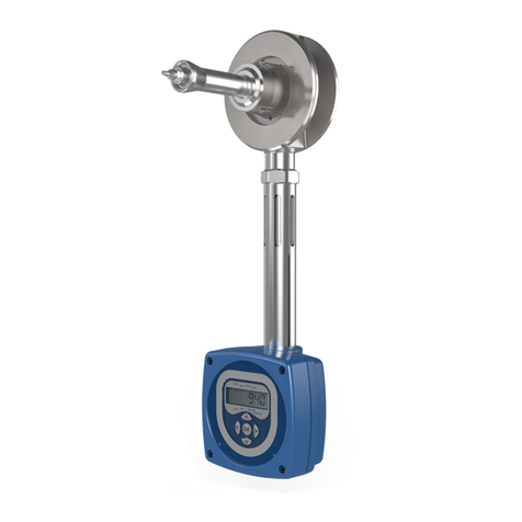
CAUTION: Do not lag the DIVA or mating flanges as this may result in excessive
temperatures in the electronics. Exceeding specified temperature limits will invalidate
the warranty and can adversely effect the performance and may damage the DIVA.
Other considerations
Be sure to allow sufficient clearance for:
-Installation of conduit/wiring. - Removal of the enclosure end caps.
-Viewing of the display. Note electronics housing and display can be rotated.
Warning: Do not install the flowmeter outdoors without additional weather protection to
prevent damage due to freezing.
3.2 Mechanical installation
Warning: Do not alter the adjustment nut at the back of the DIVAs shaft, as this will
affect the flowmeters calibration.
Orientation
The DIVA can be installed in any orientation when the pressure is below 11 bar g (160 psi g),
see Figures 3 and 4.
When the pressure is above 11 bar g the DIVA must be installed in a horizontal pipe, with the
electronics housing below the body, see Figure 4.
Ideallyinanyhorizontalorientation,theDIVAshouldbeinstalledwiththeelectronichousingbelow
the body. Where this is not possible, the DIVA can be installed with the electronics enclosure
above the body. However, the pressure of the saturated steam must be below 11 bar g (160 psi).
Note: The DIVA operates with flow in one direction only. It is not intended for use with
bi-directional flow. The DIVA is clearly marked with a direction of flow arrow.
Rotating the electronics enclosure
The electronics housing can be rotated 270°to enable sufficient clearance for installation. To
rotate the display loosen the grub screw immediately below the enclosure, rotate the enclosure
and tighten the grub screw. Warning: Do not untighten stem from the main body of the unit.
Upstream/downstream pipework
The DIVA flowmeter should be installed in pipework manufactured to BS 1600 or ANSI/ASME
B 36.10 Schedule 40, which corresponds to the following pipeline internal diameters.
Nominal diameter Nominal internal diameter
50 mm 52 mm
80 mm 77 mm
100 mm 102 mm
For different pipe standards/schedules, if the flowmeter is being operated at the extreme
of its published maximum range, and maximum accuracy is required, downstream spool
pieces manufactured from BS 1600 or ANSI/ASME B 36.10 Schedule 40 pipe should be used.
It is important that the internal upstream and downstream diameters of pipe are smooth. Ideally
seamless pipes should be used and there should be no intrusive weld beads on the internal
diameter. It is recommended that slip-on flanges be used to avoid any intrusive weld beads on
the internal diameter of the pipe.
Note: See pages 8 and 9, Figures 5 to 8 for other considerations which need to be noted
before determining the correct installation location.
3. Installation
p337_18.p65 1/27/05, 11:26 AM6
