Spirit Commercial CE850 User manual

CE850 ELLIPTICAL TRAINER
OWNER’S MANUAL
Spirit Fitness

3
www.spirittness.com
TABLE OF CONTENTS
5 PRODUCT REGISTRATION
6 IMPORTANT SAFETY INSTRUCTIONS
7 IMPORTANT ELECTRICAL INSTRUCTIONS
8 IMPORTANT OPERATION INSTRUCTIONS
10 CE850 ASSEMBLY INSTRUCTIONS
18 CONSOLE OPERATION
23 PROGRAMMABLE FEATURES
34 HEART RATE PROGRAMS
39 GENERAL MAINTENANCE
41 MANUFACTURER’S LIMITED WARRANTY
44 EXPLODED VIEW
45 PARTS LIST
Thank you for purchasing our product, please save these instructions. Please do not perform or attempt any
customizing, adjustments, repair or maintenance that is not described in this manual.

4
Spirit Fitness
Congratulations on your new elliptical trainer and welcome to the Spirit Fitness family!
Thank you for your purchase of this quality elliptical trainer from Spirit Fitness. Your new elliptical
trainer was manufactured by one of the leading tness manufacturers in the world and is backed
by one of the most comprehensive warranties available. Through your dealer, Spirit Fitness
will do all we can to make your ownership experience as pleasant as possible for many years
to come. If not purchased direct from Spirit Fitness, the local dealership where you purchased
this elliptical trainer is your administrator for all Spirit Fitness warranty and service needs. Their
responsibility is to provide you with the technical knowledge and service personnel to make your
experience more informed and any difculties easier to remedy.
Please take a moment at this time to record the name of the dealer, their telephone number,
and the date of purchase below to make any future, needed contact easy. We appreciate your
support and we will always remember that you are the reason that we are in business.
Yours in Health,
Spirit Fitness
NAME OF DEALER _____________________________________
DEALER PHONE # _____________________________________
PURCHASE DATE _____________________________________

5
www.spirittness.com
RECORD YOUR SERIAL NUMBER
Please record the serial number of this tness product in the space provided below.
Serial Number:
REGISTER YOUR PURCHASE
The self-addressed product registration card must be completed in full and returned to Spirit Fitness. You
can also go to https://www.spirittness.com/commercialwarrantyregistration.html under the Support tab
to register online.

6
Spirit Fitness
IMPORTANT SAFETY
INSTRUCTIONS
WARNING
When using an electrical appliance, basic
precautions should always be followed, including
the following:
Read all instructions before using this appliance.
DANGER – To reduce the risk of electric shock:
Always unplug this appliance from the electrical
outlet immediately after using and before cleaning.
WARNING – To reduce the risk of burns, re,
electric shock, or injury to persons, install the
elliptical on a at level surface with access to a
110-volt, 5-amp grounded outlet with only the
elliptical plugged into the circuit.
DO NOT USE AN EXTENSION CORD UNLESS
IT IS A 14AWG OR BETTER, WITH ONLY ONE
OUTLET ON THE END:
• Do not operate elliptical on deeply padded, plush or
shag carpet. Damage to both carpet and elliptical
may result.
• Keep children away from the elliptical. There are
obvious pinch points and other caution areas that
can cause harm.
• Keep hands away from all moving parts.
• Never operate the elliptical if it has a damaged cord
or plug. If the elliptical is not working properly, call
your dealer.
• Keep the cord away from heated surfaces.
• Do not operate where aerosol spray products are
being used or where oxygen is being administered.
Sparks from the motor may ignite a highly gaseous
environment.
• Never drop or insert any object into any openings.
• Do not use outdoors.
• To disconnect, turn all controls to the off position,
then remove the plug from the outlet.
• Do not attempt to use your elliptical for any purpose
other than for the purpose it is intended.
• The hand pulse sensors are not medical devices.
Their purpose is to provide you with an approximate
measurement in relation to your target heart rate. Use
of a chest transmitter strap (sold separately) is a much
more accurate method of heart rate analysis. Various
factors, including the user’s movement, may affect the

7
www.spirittness.com
accuracy of heart rate readings. The pulse sensors
are intended only as exercise aids in determining
heart rate trends in general.
• Wear proper shoes. High heels, dress shoes,
sandals or bare feet are not suitable for use on your
elliptical. Quality athletic shoes are recommended to
avoid leg fatigue.
• This appliance is not intended for use by persons
with reduced physical, sensory or metal capabilities,
or lack of experience and knowledge, unless
they have been given supervision or instruction
concerning use of the appliance by a person
responsible for their safety.
• Keep children under the age of 13 away from
this machine.
SAVE THESE INSTRUCTIONS - THINK SAFETY!
IMPORTANT ELECTRICAL
INSTRUCTIONS
WARNING
NEVER remove any cover without rst disconnecting AC
power. If voltage varies by ten percent (10%) or more,
the performance of your Elliptical may be affected.
Such conditions are not covered under your warranty.
If you suspect the voltage is low, contact your local
power company or a licensed electrician for proper
testing. NEVER expose this elliptical to rain or moisture.
This product is NOT designed for use outdoors, near a
pool or spa, or in any other high humidity environment.
The operating temperature specication is 40 to 120
degrees Fahrenheit, and humidity is 95% non-condensing
(no water drops forming on surfaces).
Circuit Breakers: Some circuit breakers used in homes
are not rated for high inrush currents that can occur
when a elliptical is rst turned on or even during use. If
your elliptical is tripping the house circuit breaker (even
though it is the proper current rating) but the circuit
breaker on the elliptical itself does not trip, you will need
to replace the home breaker with a high inrush type.
This is not a warranty defect. This is a condition we
as a manufacture have no ability to control. This part is
available through most electrical supply stores. Examples:
Grainger part # 1D237, or available online at www.squared.
com part #QO120HM. The electrical outlet used should have
a dedicated 5 amp circuit breaker.

8
Spirit Fitness
GROUNDING INSTRUCTIONS
This product must be grounded. If the elliptical
should malfunction or breakdown, grounding
provides a path of least resistance for electric
current, reducing the risk of electric shock. This
product is equipped with a cord having an
equipment-grounding plug. The plug must be
plugged into an appropriate outlet that is properly
installed and grounded in accordance with all local
codes and ordinances.
DANGER – Improper connection of the equipment-
grounding conductor can result in a risk of electric
shock. Check with a qualied electrician or
serviceman if you are in doubt as to whether the
product is properly grounded. Do not modify the
plug provided with the product if it will not t the
outlet; have a proper outlet installed by a qualied
electrician.
This product is for use on a nominal 110-volt/5
amp dedicated circuit, and has a grounding
plug that looks like the plug illustrated below. A
temporary adapter that looks like the adapter
illustrated below may be used to connect this plug
to a 2-pole receptacle as shown below if a properly
grounded outlet is not available. The temporary
adapter should be used only until a properly
grounded outlet, (shown below) can be installed by
a qualied electrician. The green colored rigid ear-
lug, or the like, extending from the adapter, must be
connected to a permanent ground such as a properly
grounded outlet box cover. Whenever the adapter is
used, it must be held in place by a metal screw.
IMPORTANT OPERATION
INSTRUCTIONS
• NEVER operate this elliptical trainer without reading
and completely understanding the results of any
operational change you request from the computer.
• Understand that changes in resistance do not occur
immediately. Set your desired resistance level on the
computer console and release the adjustment key. The
computer will obey the command gradually.

9
www.spirittness.com
• Use caution while participating in other activities while pedaling on your elliptical trainer; such as watching
television, reading, etc. These distractions may cause you to lose balance which may result in serious injury.
• Do not use excessive pressure on console control keys. They are precision set to function properly with little
nger pressure.
WARNING
This product can expose you to chemicals including Toluene and Acrylamide which are known to the State
of California to cause Cancer and birth defects or other reproductive harm. For more information, go to
www.P65Warnings.ca.gov
10
Spirit Fitness
CE850 PRE-ASSEMBLY
UNPACKING
1. Cut the straps, then lift the box over the unit and unpack.
2. Carefully remove all parts from the carton and inspect for any dam-
age or missing parts. If parts are damaged or missing, contact your
dealer immediately.
3. Locate the hardware package. Remove the tools rst. Remove the
hardware for each step as needed to avoid confusion. The numbers
in the instructions that are in parenthesis (#) are the item number from
the assembly drawing for reference.
TOOLS INCLUDED:
13/14mm Wrench
12/14mm Wrench
Phillips Screwdriver
8mm L Allen Wrench
PARTS INCLUDED:
1 Main Frame
1 Console Mast
1 Console Mast Cover
2 Swing Arms
2 Connecting Arms
6 Levelers
1 Console
2 Foot Pedals
1 Power Cord
1 Audio Cable
2 Transport Wheels
1 Hardware Kit

11
www.spirittness.com
CONSOLE
CONSOLE MAST
(Beneath Console)
CONNECTING ARM
LEVELERS
FRONT STABILIZER
REAR STABILIZER
FOOT PEDALS
MAIN FRAME
RAILS
PULSE GRIPS
SWING ARM
CONSOLE FAN

12
Spirit Fitness
CE850 STEP ZERO
1. Use the Allen Wrench (No.193) to release 2
Socket Head Cap Bolts (No.145), which are
attached to the Main Frame for securing the
Mast Tube, to remove and dispose the Side
Back (No.28).
28
145
13
www.spirittness.com
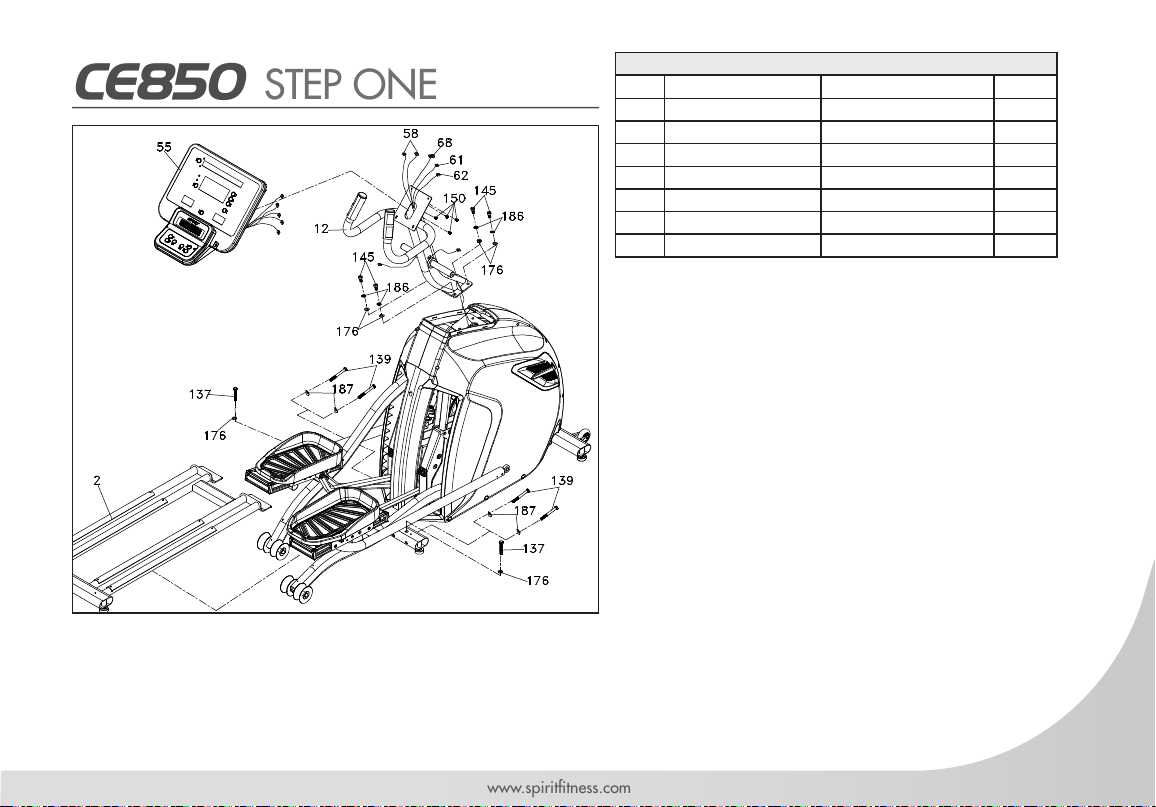
CE850 STEP ONE
HARDWARE FOR STEP 1
PART TYPE DESCRIPTION QTY
137 HEX HEAD BOLT 3/8” X 2-1/4” 2
139 HEX HEAD BOLT 3/8” X 3-3/4” 4
145 SOCKET HEAD CAP BOLT 3/8”X3/4” 4
150 SCREW M5X10 4
176 FLAT WASHER 3/8”X19X1.5T 6
186 SPRING WASHER 3/8”X2T 4
187 CURVED WASHERS 3/8” X 23 X 2T 4
1. Place 2 Flat Washers (No.176) against 2
Hex Head Bolts (No.137) and hand-tighten them
through the top of the Rear Stabilizer Tube (Main
Frame), into the Rear Rail Assembly (No.2) by
using the Wrench (No.194).
2. Place 4 Curved Washers (No.187) against 4
Hex Head Bolts (No.139) and hand-tighten them
through the Front of the Rear Stabilizer Tube, into
the Rear Rail Assembly (No.2) by using Wrench
(No.194).
3. Pierce 14P Computer Cable (No.68) from
bottom of the console mast tube through it and
pull out of the top. Use 4 Socket Head Cap Bolts
(No.145), 4 Spring Washers (No.186) and 4
Flat Washers (No.176) to secure.
4. Untie the Computer Cable (No.68) , connect 2 Handpulse W/Cable Assembly (No.58) and Handle Wire
(Upper), Resistance/ Incline (White/Red) (No.61/62) with the Console Assembly (No.55) respectively. Then
place the Console on top of the Mast and use Phillips Head Screw Driver (No.192) to tighten 4 Phillips Head
Screws (No.150) to secure.
14
Spirit Fitness
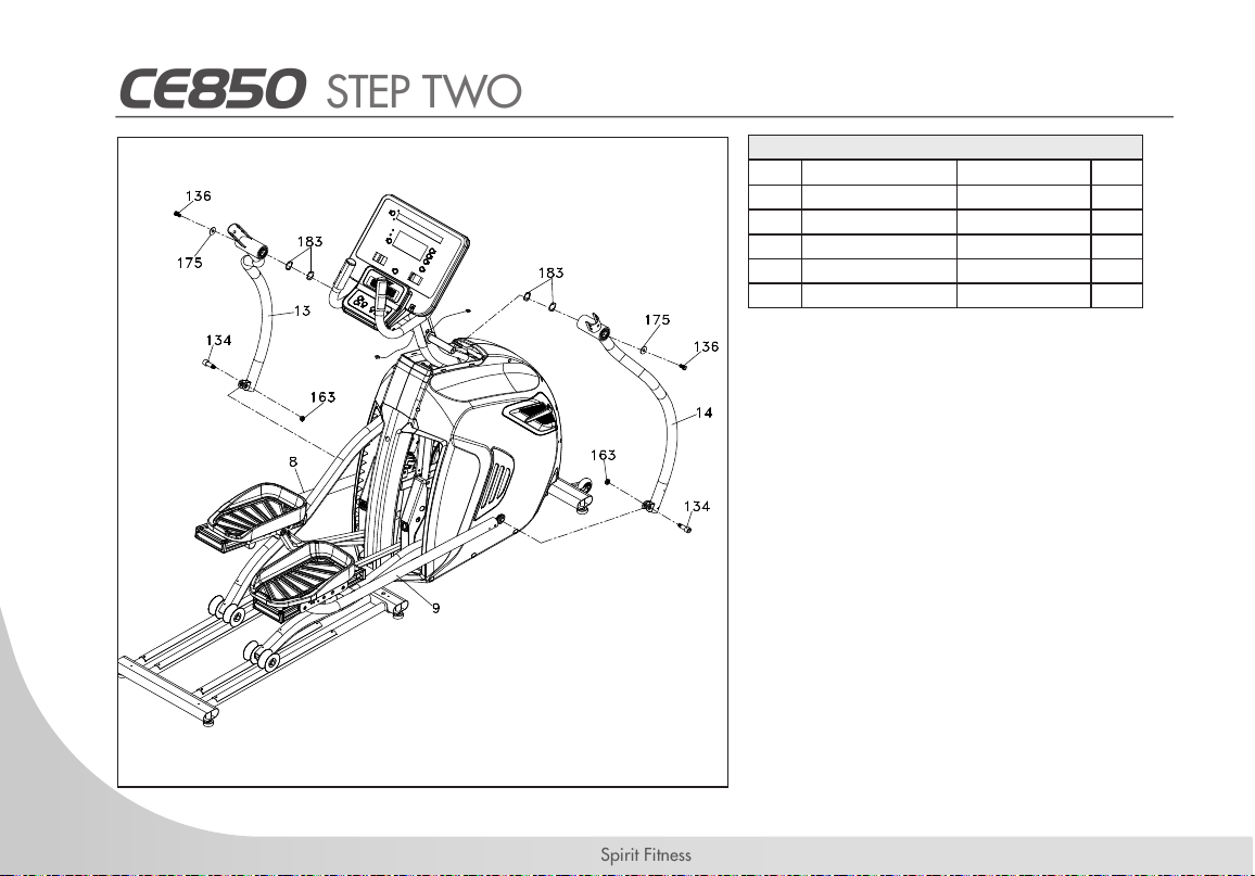
CE850 STEP TWO
HARDWARE FOR STEP 2
PART TYPE DESCRIPTION QTY
134 HEX HEAD BOLT M10 x 1.5 2
136 HEX HEAD BOLT 3/8” x 3/4” 2
163 NYLOC NUT M10 x 8T 2
175 FLAT WASHER 3/8”x 30 x 2.0T 2
183 WAVE WASHER ø25 4
1. Locate Left and Right Lower Swing Arms
(No.13, 14) together with 4 Wave Washers
(No. 183) onto Left and Right Shafts of the
console mast tube then tighten with 2 Hex
Head Bolts (No.136) and two Flat Washers
(No.175) by using the Wrench (No.194).
2. Untie the Rod End Bearing on Left
Connecting Arm (No.8) and pierce a Hex
Head Bolt (No.134) through the rod end
holes and rod end bearing then tighten
with and Nyloc Nut (No.163) by using the
Wrench (No.200) and Wrench (No.201).
Repeat for the Right Connecting Arm (No.9)
and right Lower Handle Bar (No.14).

15
www.spirittness.com
CE850 STEP THREE
HARDWARE FOR STEP 3
PART TYPE DESCRIPTION QTY
97 SWITCH WIRE CAP -2
138 HEX HEAD BOLT 3/8”X2-1/4” 6
165 NYLOC NUT 3/8”X7T 6
176 FLAT WASHER 3/8”X19X1.5T 8
187 CURVED WASHER 3/8”X23X2T 4
1. Insert Left Upper Swing Arm (No.10) onto Left
Lower Swing Arm (No.13) and secure with 3
Hex Head Bolts (No.138), 4 Flat Washers
(No.176), 2 Curved Washers (No.187) and
3 Nyloc Nuts (No.165) by using Wrench
(No.194) and Wrench (No.195). Repeat
for the Right Upper Swing Arm (No.11) and
Right Lower Swing Arm (No.14).
2. Connect Handle Wire (Upper), Resistance
(White, 61) and Handle Wire (Upper),
Incline (Red, 62) to 2 Handle Wires (Lower),
Resistance/Incline (No.63) respectively and
shove the excessive wires into the console
mast tube. Finally, plug the Switch Wire Caps
(No.97) onto the console mast tube to secure
the wires.
16
Spirit Fitness
CE850 STEP FOUR

17
www.spirittness.com
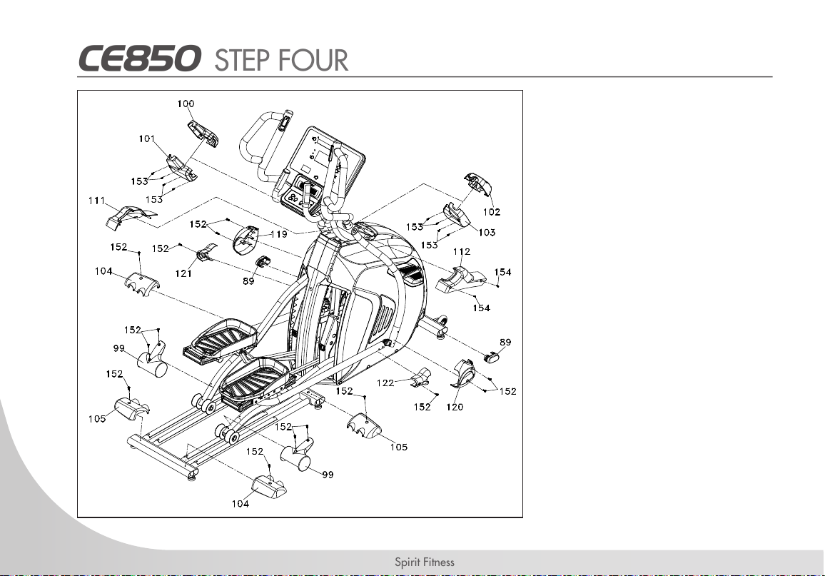
CE850 STEP FOUR
HARDWARE FOR STEP 4
PART TYPE DESCRIPTION QTY
152 PHILLIPS HEAD SCREW M5 x 15L 14
153 SHEET METAL SCREW 3.5 x 12L 8
154 SHEET METAL SCREW 4 x 15mm 2
1. Secure the Left Connecting Arm Cover B (No.121) onto the Left Connecting Arm with Phillips Head
Screw (No.152) by using the Phillips Head Screw Driver (No.192) then secure the Left Connecting Arm
Cover A (No.119) with 2 Phillips Head Screws (No.152) onto the Lower Handle Bar. Repeat the same
way for the Right Connecting Arm Cover B (No.122) and Right Connecting Arm Cover A (No.120)
onto the Right Connecting Arm and Right Lower Handle Bar, respectively.
2. Secure 2 Slide Wheel Covers (No.99) on both left and right Pedal arms with 4 Phillips Head Screws
(No.152) by using Phillips Head Screw Driver (No.192).
3. Use Phillips Head Screw Driver (No.192) with 4 Phillips Head Screws (No.152) to secure 2 Rear
Stabilizer Covers (A) (No.104) and 2 Rear Stabilizer Cover (B) (No.105) on both left and right
sides of rear tube of rear rail assembly.
4. Match the Left and Right Console Mast Covers (No.111, 112) with Left and Right side cases respectively and
secure with 2 Sheet Metal Screws (No.154) by using the Phillips Head Screw Driver (No.192).
5. Match the Front Handle Bar Cover (No.100) and Rear Handle Bar Cover (No.101) with each other on Left Lower
Handle Bar and use Phillips Head Screw Driver to tighten 4 Sheet Metal Screws (No.153). Do the same for Right
Front Handle Bar Covers (No.102) and Rear Handle Bar Cover (No.103). (Be carefeul not to pinch the wire)
6. Plug in both Oval End Caps (No.89) onto both ends of the front stabilizer tube.

18
Spirit Fitness
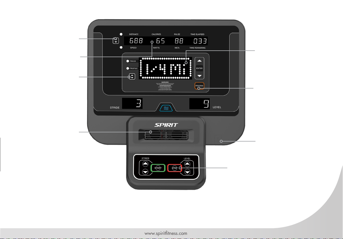
CE850 CONSOLE OPERATION
19
www.spirittness.com
Fan
Scan Button for
LED Windows
Scan Button for
Dot Matrix
Dot Matrix
Message Center
Start, Stop, Level
Controls
Up, Down,
Program Controls
LED Data Display
Windows
USB
Charger

20
Spirit Fitness
POWER
When initially powered on the console will perform an internal self-test. During this time all the lights will turn
on. When the lights go off, the Dot Matrix Message Center will show the software version (i.e.: VER 1.0).
The LED Data Display Windows show the distance in miles and shows the total hours of use. The odometer
will remain displayed for only a few seconds then the console will go to the start up display. The Dot Matrix
Message Center will be scrolling through the different proles of the programs and will be scrolling the start
up message. You may now begin to use the console.
C-SAFE FEATURE
Your console is equipped with a C-SAFE feature. The Power (POWER) port can be used for powering a
remote controlled audio-visual system by connecting a cable from the remote to the Power port at the back of
the console. The Communication port (COMM) can be used to interact with tness software applications.
QUICK START
This is the quickest way to start a workout. After the console powers up you just press the Start key to begin.
This will initiate the Quick Start mode. In Quick Start the Time will count up from zero, all workout data will
start to accrue and the workload may be adjusted manually by pressing the Up and Down buttons. The Dot
Matrix Message Center will show a ¼ mile (0.4km) track display or just the bottom row lit at rst, depending
on how the display button has been set (see Basic information below). As you increase the workload, more
rows will light indicating a harder workout. The elliptical will get harder to pedal as the rows increase. The
Dot Matrix Message Center has 24 columns of lights and each column represents 1 minute. At the end of
the 24th column (or 24 minutes of work) the display will wrap around and start at the rst column again.
There are 20 levels of resistance – displayed as 10 rows of lights - available for plenty of variety. The rst
5 levels are very easy workloads, and the changes between levels are set to a good progression. for de-
Table of contents
Other Spirit Commercial Elliptical Trainer manuals


Popular Elliptical Trainer manuals by other brands

NordicTrack
NordicTrack 14.0 Elliptical user manual

Garmin
Garmin Forerunner 301 - Running GPS Receiver owner's manual

Sunny Health & Fitness
Sunny Health & Fitness SF-E3988 user manual

Fuel Fitness
Fuel Fitness AVENGER FUL0005 owner's manual

NordicTrack
NordicTrack CXT 910 user manual

Hotel Fitness
Hotel Fitness Hotel Fitness Xt9800 Elliptical manual


