SPIT 372 Manual

Manual de utilização e 37
manutenção
Bruks- och 43
underhållsanvisning
Drifts- og 49
vedligeholdelsesvejledning
Instruksjoner om bruk og 55
vedlikehold
Käyttö- ja huolto-ohjeet 61
Oδηγίες χρήσης 67
Notice d’emploi et Page 1
d’entretien
Operating and maintenance 7
instructions
Bedienungs- und 13
Wartungsanleitung
Istruzioni d’uso e 19
manutenzione
Gebruiks- en 25
onderhoudsaanwijzingen
Instrucciones de empleo y 31
mantenimiento
FR
GB
DE
IT
NL
ES
372
PT
SE
DK
NO
FI
GR
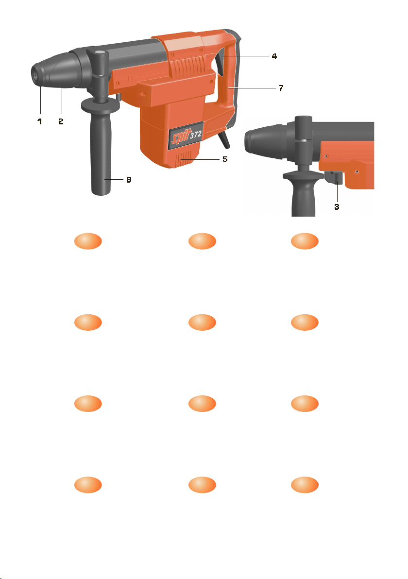
1) Capuchon anti-poussière
2) Manchon de verrouillage
3) Sélecteur de fonction
4) Interrupteur électronique
5) Ouïes de ventilation
6) Poignée orientable
7) Poignée
FR
1) Dust cap
2) Locking sleeve
3) Mode selector switch
4) Electronic switch
5) Ventilation slots
6) Adjustable handle
7) Handle
GB
1) Stofbeschermkap
2) Vergrendelingsmof
3) Functieschakelaar
4) Elektronische schakelaar
5) Ventilatieopeningen
6) Verdraaibare handgreep
7) Handgreep
NL
1) Dammkåpa
2) Klämhylsa
3) Funktionsväljare
4) Elektronisk strömbrytare
5) Ventilationsöppningar
6) Inställbart handtag
7) Handtag
SE
1) Pölysuoja
2) Kiinnitysholkki
3) Käyttötavan valintakytkin
4) Elektroninen kytkin
5) Tuuletusraot
6) Liikkuva lisäkahva
7) Kädensija
FI
1) Staubschutzkappe
2) Verriegelungshülse
3) Betriebsartenwahlschalter
4) Elektronikschalter
5) Lüftungsschlitze
6) Verstellbarer Zusatzgriff
7) Handgriff
DE
1) Caperuza antipolvo
2) Casquillo de enclavamiento
3) Selector de modo de operación
4) Interruptor electrónico
5) Aberturas de ventilación
6) Empuñadura orientable
7) Empuñadura
ES
1) Støvdæksel
2) Låsekappe
3) Funktionsvælger
4) Elektronisk kontakt
5) Ventilationshuller
6) Drejeligt håndtag
7) Håndtag
DK
1) Κάλυµµα σκνης
2) ∆ακτύλιος ασφάλισης
3) ∆ιακπτης επιλογής τύπου λειτουργίας
4) Ηλεκτρονικς διακπτης
5) Εγκοπή αερισµού
6) Μετακινούµενη πρσθετη χειρολαβή
7) λαβή
GR
1) Cappuccio antipolvere
2) Bussola di bloccaggio
3) Selettore di funzione
4) Interruttore elettronico
5) Feritoie per la ventilazione
6) Impugnatura orientabile
7) Impugnatura
IT
1) Capa de protecção contra o pó
2) Lluva de travamento
3) Selector de tipo de funcionamento
4) Interruptor electrónico
5) Aberturas de ventilação
6) Punho orientável
7) Punho
PT
1) Støvkappe
2) Låsehylse
3) Funksjonsvalgbryter
4) Elektronisk På / Av bryter
5) Ventilasionsspalter
6) Justerbart håndtak
7) Håndtak
NO
12
4
7
5
6
3

Consignes de sécurité
1
Veuillez observer le dessin d’outil sur la partie intérieure avant!
■Pour travailler en toute sécurité avec l’appareil, il convient
de lire soigneusement la notice d’emploi et d’entretien,
ainsi que les consignes de sécurité, et d’observer les direc-
tives correspondantes. Veuillez vous faire donner des
conseils pratiques avant la première utilisation.
■Vérifiez le câble et la fiche de l’appareil avant chaque utilisation. En
cas de détérioration, les faire réparer par un homme de l’art.
■Afin d’éviter tous risques, si le câble de connexion est
endommagé, celui-ci doit être remplacé par le fabricant ou son
service de réparation.
■Ne branchez la fiche du câble de l’appareil au secteur que si l’ap-
pareil est hors service.
■L’appareil est muni d’un limiteur de couple qui protège l’opérateur
en cas de coincement de la mèche. Ce couple n’est toutefois
contrôlé que si l’utilisateur tient fermement l’appareil à deux
mains en ayant un appui stable (ce qui exclut par exemple
l’utilisation sur une échelle).
■L’appareil ne doit jamais être humide, ni être utilisé dans un envi-
ronnement humide.
■L’appareil ne doit jamais être utilisé sans poignée orientable (6).
■Ne pas approcher les mains des outils en rotation.
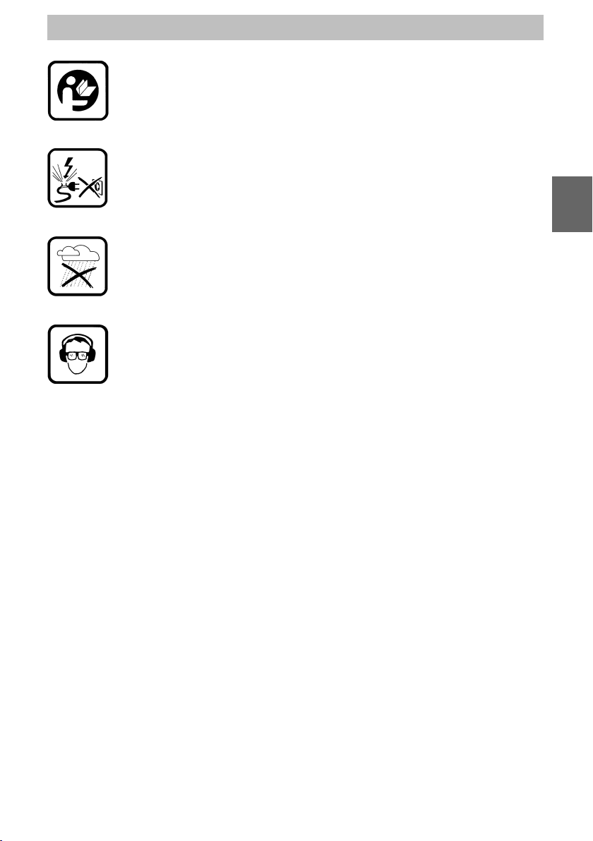
■Le port de lunettes de protection, d’une protection acoustique,
d’un masque de protection anti-poussière, ainsi que de gants de
protection et de chaussures de sécurité, est obligatoire.
■Faites attention aux canalisations électriques et aux tuyauteries de
gaz et d’eau se trouvant dans les murs.
■N’utilisez que des accessoires d’origine.
En cas de non-respect des instructions de
sécurité et des prescriptions des accidents, il
y a un risque de blessure!
Ne pas oublier de lire le manuel additionnel
‘Instructions de sécurité’!
FR
Mesuré suivant la norme EN 60745. Le niveau sonore A type de
l’appareil comporte :
niveau de pression acoustique :
burin : 1(97 + 3) dB(A) foret : 1(95 + 3) dB(A)
niveau de puissance acoustique
burin : (108 + 3) dB(A) foret : (106 + 3) dB(A)
Toujours porter une protection acoustique!
La valeur mesurée type de l’accélération à la poignée arrière est de
18,8 m/s2(burin) 18,7 m/s2(foret).
La valeur mesurée type de l’accélération à la poignée avant est de
13,3 m/s2(burin) 12,7 m/s2(foret).
Nous déclarons sous notre propre responsabilité que ce produit est
en conformité avec les normes ou documents :
IEC 60745-1, IEC 60745-2-6, EN 60745-1, EN60745-2-6, EN 55014,
EN 61000-3, EN 55104, conformes aux règlementations 73/23/CEE,
89/336/CEE, 98/37/CE
Didier BOURRETTE Jens STELLWAG
SPIT S.A., Route de Lyon - B.P. 104, F-26501 Bourg-les-Valence
2
Informations techniques
Caractéristiques
techniques
Porte-outil……………………………………………………… S2S max
Tension……………………………………………110 V …………230 V
Fréquence………………………………………………………50-60 Hz
Intensité …………………………………………10,8 A …………5,7 A
Puissance ………………………………………………………1250 W
Vitesse de rotation en charge …………………………… 0 - 260 min-1
Cadence de frappe en charge ………………………… 0 - 2700 min-1
Energie d’impact …………………………………………………… 10 J
Poids de l’appareil…………………………………………………7,9 kg
Longueur du câble ………………………………………………… 4 m
Charbons ……………………………………………… auto-coupants
Lubrification ……………………………………par l’huile longue durée
Positionnement de la mèche ……………………………… 8 positions
Interrupteur de l’appareil ……………… avec électronique de pilotage
Mode de protection classe II ………………………………………
Distance mini du mur pour percer …………………………… 39 mm
Encombrement (mm) ………………………………… 480 x 280 x 120
Niveau sonore
Vibrations
Déclaration
de conformité
3
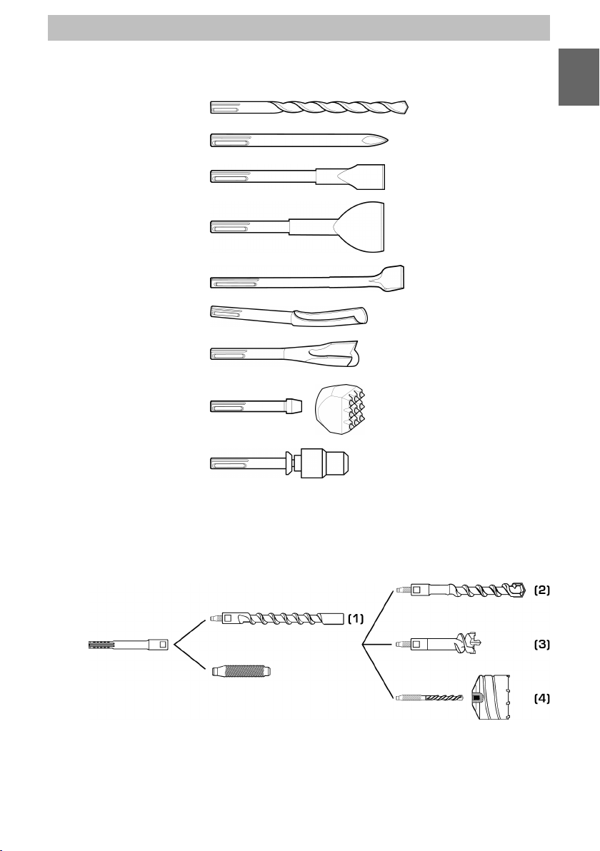
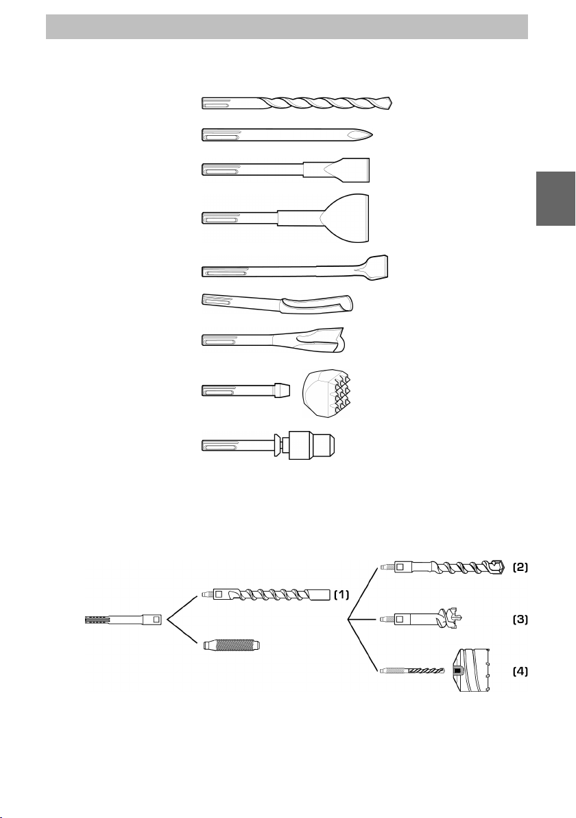
Outillage adapté
Outillage S2S MAX
Système Turbo Kit
Foret (Ø 14 à Ø 45 mm)
Pic
Burin
Pelle large
Pelle coudée
Gouge béton
Gouge brique
Porte-boucharde et
boucharde
Adaptateur foret S2S
(1) L = 280 mm
(2) Ø 28, Ø 30, Ø 32 mm - L utile = 400 mm
(3) Ø 35, Ø 40, Ø 45, Ø 50, Ø 55, Ø 60, Ø 68, Ø 80 mm
(4) Ø 65, Ø 80, Ø 90, Ø 100, Ø 125 mm
FR

4
Instructions de service
Avant la mise en
service
Domaine d’utilisa-
tion
Interrupteur
marche/arrêt
électronique
Mise en fonction-
nement / Arrêt
Poignée supplé-
mentaire
Limiteur de couple
Attention à la tension du réseau: Elle doit correspondre aux indica-
tions de la plaque signalétique de l’appareil.
Cet appareil est uniquement destiné à percer et buriner principalement
les matières premières minérales (par ex. le béton, l’ouvrage de ma-
çonnerie, le grès argilo-calcaire, …). Une utilisation inappropriée peut
occasionner des blessures ou endommager l’appareil. pour lequel l’u-
tilisateur est responsable.
L’interrupteur électronique (4) est conçu pour une adaptation en conti-
nu de la vitesse de rotation et de l’énergie d’impact aux conditions
d’utilisation (crépi, carrelage, brique, béton).
Plus l’interrupteur est enfoncé, plus la vitesse de rotation et l’énergie
d’impact augmentent.
Après avoir introduit l’outil dans le porte-outil et réglé le sélecteur de
fonction (3) dans la position adaptée, appuyer la machine contre le
support et actionner l’interrupteur électronique (4).
Pour arrêter la machine, relâcher l’interrupteur électronique (4).
Ne pas utiliser l’appareil sans sa poignée orientable (6).
La rotation de la poignée orientable est de 360°. Desserrer le manche
de la poignée orientable et l’orienter dans la position qui correspond
le mieux à la position de travail.
Resserrer soigneusement la poignée après obtention du réglage sou-
haité.
Si l’outil de perçage se coince ou reste bloqué, le limiteur de couple
arrête la rotation ce qui évite une perte de contrôle de l’appareil.
L’appareil doit être tenu fermement à deux mains et l’utilisateur doit
avoir un appui stable (ce qui exclut par ex. tout travail sur une échelle).

5
Sélecteur de
fonction
Perçage en frappe
Position du burin
Burinage
(stop de rotation)
Le sélecteur de fonction (3) ne doit être activé qu’à l’arrêt total de la
machine!
Instructions de service
Pour tous travaux de perçage
Permet d’orienter le burin dans
une position de travail confor-
table et efficace
Pour tous travaux de piquage
et de burinage
FR

6
Instructions de service
Montage
Démontage
Maintenance
Evacuation des
déchets
Abaisser le manchon de verrouilla-
ge (2), introduire l’outil dans le
porte-outil et, en exerçant une
légère pression, le tourner légère-
ment jusqu’à ce qu’il glisse dans le
porte-outil. L’outil est verrouillé dès
que le manchon de verrouillage est
relâché.
Contrôler s’il est bien verrouillé
en tirant fortement sur l’outil.
Abaisser le manchon de verrouilla-
ge (2) et retirer l’outil.
Attention! Les outils deviennent
extrêmement chauds lors du tra-
vail, c’est pourquoi ils ne doivent
jamais être saisis à main nue. Il y a
un risque de blessure!pour lequel
l’utilisateur est responsable.
Avant toute intervention sur l’appareil proprement dit, toujours
extraire la fiche du cordon d’alimentation hors de la prise élec-
trique!
Graisser la queue des outils à intervalles réguliers. Ceci augmente
considérablement la longévité du porte-outil.
Le capuchon anti-poussière (1) empêche la pénétration de poussières
pendant le travail. Il doit être remplacé s’il est usé ou endommagé.
Les ouïes de ventilation (5) doivent être maintenue propres et dégagées.
L’appareil est muni de charbons auto-coupants. Lorsque les char-
bons sont usés, le moteur est automatiquement mis hors tension.
Une intervention de maintenance systématique est alors requise.
Tous les travaux d’entretien et de réparation devront être exécutés par
les ateliers SPIT ou par un service de réparation autorisé par SPIT. En
cas de demande de renseignements complémentaires, sélectionnez
un des numéros de téléphone mentionnés (sur la page de couverture
intérieure de derrière).
SPIT n’assumera aucune responsabilité pour les appareils qui n’ont
pas été entretenus, réparés ou modifiés dans les ateliers formellement
autorisés par SPIT.
Pour éviter des accidents, des blessures ou des dégâts à l’appareil,
nous recommandons de faire entretenir l’appareil à des intervalles de
temps réguliers – en fonction de la fréquence d’utilisation.
Pour les pays européens uniquement
Ne pas jeter les appareils électriques dans les ordures ménagères !
Conformément à la directive européenne 2002/96/EG relative aux déchets
d’équipements électriques ou électroniques (DEEE), et à sa transposition
dans la législation nationale, les appareils électriques doivent être collectés
à part et être soumis à un recyclage respectueux de l’environnement.

7
For your safety
Please observe the general drawing and explanations on the inner
cover!
■This machine can be operated safely only when the operat-
ing instructions have been completely read and strictly
observed to. It is recommended to receive practical
instruction before using the machine for the first time.
■Always inspect cable and plug before using the machine. Have
damage repaired only by a qualified professional.
■In order to avoid any risks, the connecting cable – if damaged –
has to be replaced by the manufacturer or his agency.
■Insert plug in power supply socket only when machine is switched
off.
■The tool is provided with a torque limiter which protects the oper-
ator if the drill bit gets stuck. This torque is however controlled only
if the user is holding the tool firmly with both hands and is
in a stable position (e.g. not on a ladder).
■The machine must not be used when damp and must not be
operated in wet environment.
■Never use the machine without the auxiliary handle (6).
■Do not touch rotating tools.
■Use safety glasses, ear protectors, dust protection mask as well
as wear protective gloves and safety shoes.
■Beware of electric lines, gas and water pipes embedded in walls.
■Use only genuine accessories.
Non-observance of the safety instructions and
the prescriptions regarding the prevention of
accidents will occur the risk of injury!
See enclosure for further safety instructions!
GB

Noise
Vibration
Declaration
of conformity
Measured values determined according to EN 60745. Typically the A-
weighted noise levels of the tool are:
Sound pressure level chisel: 1(97 + 3) dB(A) drill: 1(95 + 3) dB(A)
Sound intensity level chisel: (108 + 3) dB(A) drill: (106 + 3) dB(A)
Wear ear protection!
The typical weighted acceleration at rear handle is
18,8 m/s2(chisel) 18,7 m/s2(drill).
The typical weighted acceleration at front handle is
13,3 m/s2(chisel) 12,7 m/s2(drill).
We declare under our sole responsibility that this product is in con-
formity with the following standards or standardized documents:
IEC 60745-1, IEC 60745-2-6, EN 60745-1, EN60745-2-6, EN 55014,
EN 61000-3, EN 55104, in accordance with the regulations
73/23/EEC, 89/336/EEC, 98/37/EC
Didier BOURRETTE Jens STELLWAG
SPIT S.A., Route de Lyon - B.P. 104, F-26501 Bourg-les-Valence
8
Technical information
Characteristics Tool fixing ……………………………………………………… S2S max
Voltage……………………………………………110 V …………230 V
Frequency ………………………………………………………50-60 Hz
Amperage ………………………………………10.8 A …………5.7 A
Power input………………………………………………………1250 W
Rotation speed ……………………………………………0 - 260 min-1
Hammer rate strokes ……………………………………0 - 2700 min-1
Impact energy ………………………………………………………10 J
Weight………………………………………………………………7.9 kg
Cable length …………………………………………………………4 m
Carbons ………………………………………………self-disconnecting
Lubrication …………………………………………………oil lubrication
Angle of chisel ………………………………………………8 positions
Switch ……………………………………………with electronic control
Class II …………………………………………………………………
Min. distance from the wall in order to drill ……………………39 mm
Dimensions (mm)………………………………………480 x 280 x 120

9
Suitable tooling
S2S MAX tooling
Turbo Kit system
Drill bit (dia 14 ➜dia 45 mm)
Pick
Chisel
Wide recessing tool
Bent recessing tool
concrete gouge
Brick gouge
Bush-hammer holder and
bush-hammer
S2S Drill bit adapter
(1) L = 280 mm
(2) Ø 28, Ø 30, Ø 32 mm - useful length = 400 mm
(3) Ø 35, Ø 40, Ø 45, Ø 50, Ø 55, Ø 60, Ø 68, Ø 80 mm
(4) Ø 65, Ø 80, Ø 90, Ø 100, Ø 125 mm
GB

10
Instructions for use
Before using the
equipment
Area of use
Electronic on/off
switch
Starting/ stopping
Auxiliary handle
Torque limitation
Consider the main voltage: The voltage of the source of supply is
the same that shown on the information plate on the equipment.
This tool is solely determined for hammer drilling and chiseling mainly
mineral materials (e.g. concrete, masonry, limestone, …). Improper
use may cause injury or damage the tool.
The electronic switch (4) is designed for continuous adaptation of the
rotation speed and impact energy to suit all operating conditions
(pebble dash, tiling, brick, concrete).
The further you press the switch, the higher the rotation speed and
impact energy.
After inserting the tool in the tool holder and putting the mode selec-
tor switch (3) in the right position, press the tool against the support
and operate the electronic switch (4).
To stop the tool, release the electronic switch (4).
Do not use the tool without its adjustable handle (6).
The adjustable handle rotates through 360°.
Undo the adjustable handle and put it in the position which best suits
the work position.
Tighten the handle carefully after you have put it in the desired posi-
tion.
If the drilling tool gets stuck, the torque limiter stops rotation, which
avoids losing control of the tool.
The tool must be held firmly with both hands and the user must be in
a stable position (e. g. not on a ladder).

11
Mode selector
switch
Hammer action
Position of the
chisel
Chiseling
(rotation stop)
The mode selector switch (3) must be operated only when the tool
has stopped completely!
Instructions for use
For any drilling work
Enables the chisel to be orient-
ed in a comfortable and effi-
cient working position
For any dressing and chiseling
work
GB
12
Instructions for use
Inserting the tool
Removing the tool
Maintenance
Disposal
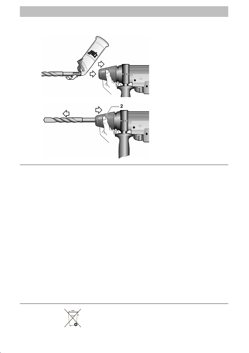
Pull down the locking sleeve (2),
insert the tool in the tool holder
and, exerting light pressure, turn it
slightly until it slides into the tool
holder.
The tool is locked as soon as the
locking sleeve is released.
Check whether it is properly
locked by pulling hard on the
tool.
Pull down the locking sleeve (2)
and pull out the tool.
Warning! The tools become hot
during use. For this reason, never
touch with your bare hands (risk of
injury)!
Before doing any work on the tool itself, always take plug out
of the socket!
Lubricate the shaft of the tools at regular intervals. This considerably
increases the lifetime of the tool holder.
The dust cap (1) prevents the ingress of dust during work. It must be
replaced if it is worn or damaged.
The ventilation slots (5) must be kept clean and clear.
The machine has self-disconnecting carbon brushes. When the
brushes are worn the motor will switch off automatically, then a rou-
tine-service is necessary.
Any maintenance or repair work must be carried out in the SPIT after-
sales service or in an after-sales service station formally approved by
SPIT.
For queries, please phone one of the numbers listed on the last page
of this booklet.
SPIT will not be responsible for any tools which have been maintained,
repaired or modified by agents not formally approved by SPIT.
We advise you to bring the tool in regular times in service for mainte-
nance according to the frequency of usage in order to prevent acci-
dents, injuries or the damage of the tool.
Only for EU countries
Do not dispose of electric tools together with household waste material!
In observance of European Directive 2002/96/EC on waste electrical and
electronic equipment and its implementation in accordance with national
law, electric tools that have reached the end of their life must be collec-
ted separately and returned to an environmentally compatible recycling
facility.
Sicherheitshinweise
13
Bitte beachten Sie die Geräteübersicht auf der vorderen inneren Um-
schlagseite!
■Gefahrloses Arbeiten ist mit dem Gerät nur möglich, wenn
Sie die Bedienungsanleitung und die Sicherheitshinweise
vollständig lesen und die darin enthaltenen Anweisungen
befolgen. Lassen Sie sich vor dem ersten Gebrauch prak-
tisch einweisen.
■Vor jeder Benutzung Gerät, Kabel und Stecker überprüfen. Schä-
den nur von einem Fachmann beseitigen lassen.
■Wenn die Anschlussleitung beschädigt wird, muss sie vom Her-
steller oder seinem Kundendienstvertreter ersetzt werden, um
Gefährdungen zu vermeiden.
■Netzstecker nur bei ausgeschaltetem Gerät in die Steckdose ein-
stecken.
■Das Gerät ist mit einer Drehmomentbegrenzung ausgestattet, die
den Benutzer schützt, wenn der Bohrer einmal blockieren sollte.
Die Drehmomentkontrolle ist jedoch nur wirksam, wenn der Be-
nutzer das Gerät fest mit beiden Händen hält und für einen
sicheren Stand sorgt (z. B. nicht auf Leitern).
■Das Gerät darf nicht feucht sein und auch nicht in feuchter Um-
gebung betrieben werden.
■Das Gerät darf nicht ohne Zusatzhandgriff (6) betrieben werden.
■Hände weg von rotierenden Werkzeugen.
■Schutzbrille, Gehörschutz, Staubschutzmaske, sowie Schutzhand-
schuhe und Sicherheitsschuhe tragen.
■Vorsicht vor in Wänden liegenden elektrischen Leitungen, Gas- und
Wasserrohren.
■Nur Original-Zubehör verwenden.
Bei Nichtbeachtung der Sicherheitshinweise
und der allg. Unfallverhütungsvorschriften
droht Verletzungsgefahr!
Weitere Sicherheitshinweise siehe Beilage!
DE
Geräusch
Vibration
Konformi-
tätserklärung
Messwert ermittelt entsprechend EN 60745. Der A-bewertete Ge-
räuschpegel des Gerätes beträgt typischerweise:
Schalldruckpegel Meißel: 1(97 + 3) dB(A) Bohrer: 1(95 + 3) dB(A)
Schallleistungspegel Meißel: (108 + 3) dB(A) Bohrer: (106 + 3) dB(A)
Gehörschutz tragen!
Die bewertete Beschleunigung beträgt typischerweise am hinteren
Handgriff 18,8 m/s2(Meißel) 18,7 m/s2(Bohrer)
Die bewertete Beschleunigung beträgt typischerweise am vorderen
Handgriff 13,3 m/s2(Meißel) 12,7 m/s2(Bohrer)
Wir erklären in alleiniger Verantwortung, dass dieses Produkt mit den
folgenden Normen oder normativen Dokumenten übereinstimmt:
IEC 60745-1, IEC 60745-2-6, EN 60745-1, EN60745-2-6, EN 55014,
EN 61000-3, EN 55104, gemäß den Bestimmungen der Richtlinien
73/23/EEC, 89/336/EEC, 98/37/EC
Didier BOURRETTE Jens STELLWAG
SPIT S.A., Route de Lyon - B.P. 104, F-26501 Bourg-les-Valence
14
Technische Information
Kenndaten Werkzeugaufnahme ………………………………………… S2S max
Spannung ………………………………………110 V …………230 V
Frequenz ………………………………………………………50-60 Hz
Stromstärke ……………………………………10,8 A …………5,7 A
Aufnahmeleistung ………………………………………………1250 W
Lastdrehzahl ……………………………………………… 0 - 260 min-1
Lastschlagzahl…………………………………………… 0 - 2700 min-1
Einzelschlagenergie………………………………………………… 10 J
Maschinengewicht ………………………………………………7,9 kg
Kabellänge…………………………………………………………… 4 m
Kohlen ……………………………………………… selbstabschaltend
Schmierung…………………………………………Öl dauergeschmiert
Meißelstellungen ………………………………………… 8 Positionen
Geräteschalter …………………………………… mit Steuerelektronik
Schutzklasse II ………………………………………………………
Mindestabstand von der Wand beim Bohren ………………… 39 mm
Abmessungen (mm) ………………………………… 480 x 280 x 120
15
Adaptierbare Werkzeuge
Werkzeug
S2S MAX
Turbo Kit System
Bohrer (Ø 14 ➜Ø 45 mm)
Spitzmeißel
Flachmeißel
Breitmeißel
Abgewinkelter Meißel
Beton-Hohlmeißel
Ziegel-Hohlmeißel
Stockhammerträger und
Stockhammer
Übergangsstück für
Bohrer
(1) L = 280 mm
(2) Ø 28, Ø 30, Ø 32 mm - Nutzlänge = 400 mm
(3) Ø 35, Ø 40, Ø 45, Ø 50, Ø 55, Ø 60, Ø 68, Ø 80 mm
(4) Ø 65, Ø 80, Ø 90, Ø 100, Ø 125 mm
DE

16
Gebrauchsanweisung
Vor der Inbetrieb-
nahme
Anwendungs-
bereich
Elektronischer
Ein- / Ausschalter
Ein- / Ausschalten
Zusatzhandgriff
Drehmoment-
begrenzung
Netzspannung beachten: Die Spannung der Stromquelle muss mit
den Angaben auf dem Typenschild des Gerätes übereinstimmen.
Dieses Gerät ist ausschließlich zum Hammerbohren und Meißeln
überwiegend mineralischer Werkstoffe (z. B. Beton, Mauerwerk,
Kalksandstein, ...) bestimmt. Ein unsachgemäßer Gebrauch kann
Verletzungen verursachen oder das Gerät beschädigen.
Der elektronische Schalter (4) ist so ausgelegt, dass Drehzahl und
Einzelschlagenergie kontinuierlich auf die Einsatzbedingungen (Putz,
Fliesen, Ziegel, Beton) abgestimmt werden können.
Je weiter der Schalter eingedrückt wird, desto höher sind Drehzahl
und Einzelschlagenergie.
Nachdem das Werkzeug in den Werkzeughalter eingesetzt und der
Betriebsartenwahlschalter (3) in die entsprechende Position gebracht
wurde, die Maschine am zu bearbeitenden Material ansetzen und den
elektronischen Schalter (4) betätigen.
Zum Abschalten der Maschine den elektronischen Schalter (4) wieder
loslassen.
Das Gerät darf nicht ohne Zusatzhandgriff (6) betrieben wer-
den.
Der verstellbare Zusatzgriff kann um 360° gedreht werden. Den Zu-
satzgriff lösen und in die gewünschte Arbeitsposition bringen.
Anschließend den Griff wieder sorgfältig anziehen.
Wenn das Bohrwerkzeug einmal klemmen oder blockieren sollte, wird
die Drehung von einer Drehmomentbegrenzung unterbrochen, damit
das Gerät nicht außer Kontrolle gerät.
Voraussetzung ist, dass der Benutzer das Gerät fest mit beiden Hän-
den hält und einen sicheren Stand hat (z. B. nicht auf Leitern).

17
Betriebswahl-
schalter
Schlagbohren
Position des
Meißels
Meißelarbeiten
(Drehstopp)
Betriebswahlschalter (3) nur im Stillstand betätigen!
Gebrauchsanweisung
Für alle Bohrarbeiten
Ermöglicht die Ausrichtung des
Meißels in eine komfortable,
wirksame Arbeitsposition
Für alle Meißelarbeiten
DE
18
Gebrauchsanweisung
Einsetzen des
Werkzeugs
Entnehmen des
Werkzeugs
Wartung
Entsorgung
Die Verriegelungshülse (2) nach un-
ten ziehen, das Werkzeug in den
Werkzeughalter einsetzen und mit
leichtem Druck etwas drehen, bis
es sich in den Werkzeughalter
schiebt.
Sobald die Verriegelungshülse wie-
der losgelassen wird, ist das Werk-
zeug verriegelt.
Kräftig am Werkzeug ziehen,
um zu überprüfen, ob es sicher
verriegelt ist.
Die Verriegelungshülse (2) nach
unten ziehen und das Werkzeug
entnehmen.
Achtung! Die Werkzeuge werden
beim Arbeiten heiß. Deshalb nicht
mit bloßen Händen anfassen!
Es droht Verletzungsgefahr!
Vor allen Arbeiten am Gerät grundsätzlich den Netzstecker zie-
hen!
Die Werkzeugschäfte müssen in regelmäßigen Abständen geschmiert
werden. Die Lebensdauer des Werkzeughalters erhöht sich dadurch
beträchtlich.
Die Staubschutzkappe (1) verhindert das Eindringen von Bohrstaub
während des Betriebs. Sie muss ausgetauscht werden, sobald sie ab-
genutzt oder beschädigt ist.
Die Lüftungsschlitze (5) müssen immer sauber und frei sein.
Das Gerät hat selbstabschaltende Kohlebürsten. Bei abgenutzten
Bürsten schaltet der Motor automatisch ab. Danach ist ein Routine-
Service fällig.
Sämtliche Wartungs- und Reparaturarbeiten müssen durch SPIT
Werkstätten oder durch einen von SPIT autorisierten Reparaturservice
ausgeführt werden.
Bei Rückfragen wählen Sie bitte eine der (auf der hinteren inneren Um-
schlagseite) aufgeführten Telefonnummern.
SPIT übernimmt keine Haftung für Geräte, die nicht in förmlich durch
SPIT zugelassenen Werkstätten gewartet, repariert oder abgeändert
wurden.
Um Unfälle, Verletzungen oder Schäden am Gerät zu vermeiden,
empfehlen wir, das Gerät in regelmäßigen Abständen – abhängig von
der Nutzungshäufigkeit – warten zu lassen.
Nur für EU-Länder
Werfen Sie Elektrowerkzeuge nicht in den Hausmüll!
Gemäss Europäischer Richtlinie 2002/96/EG über Elektro- und
Elektronik-Altgeräte und Umsetzung in nationales Recht müssen ver-
brauchte Elektrowerkzeuge getrennt gesammelt und einer umweltge-
rechten Wiederverwertung zugeführt werden.
Table of contents
Languages:
Other SPIT Rotary Hammer manuals


Popular Rotary Hammer manuals by other brands


VITO
VITO Pro-Power VIBBSFL20 instruction manual

Stanley
Stanley FATMAX SFMEH200 Original instructions

Bosch
Bosch 3 611 B4A 000 Repair instructions

EINHELL Bavaria
EINHELL Bavaria BRH 920 E operating instructions

Hitachi
Hitachi DH 24PC2 Instruction and safety manual

DeWalt
DeWalt XR DCH733 Original instructions


