2
Performer
m1000
Mono Power Amplifier
VOLTAiR
120V DC Audio Ra il
PWRPROTECT TEMP
AVIS: RISQUE DE CHO C ÉLECTRIQUE • NE PAS OUVRIR
RISK OF ELECTRIC SHOCK
DO NOT OPEN
CAUTION
1. Remove Fuse Holder
2. Exchange Fuses
3. Flip Over
4. Reinstall
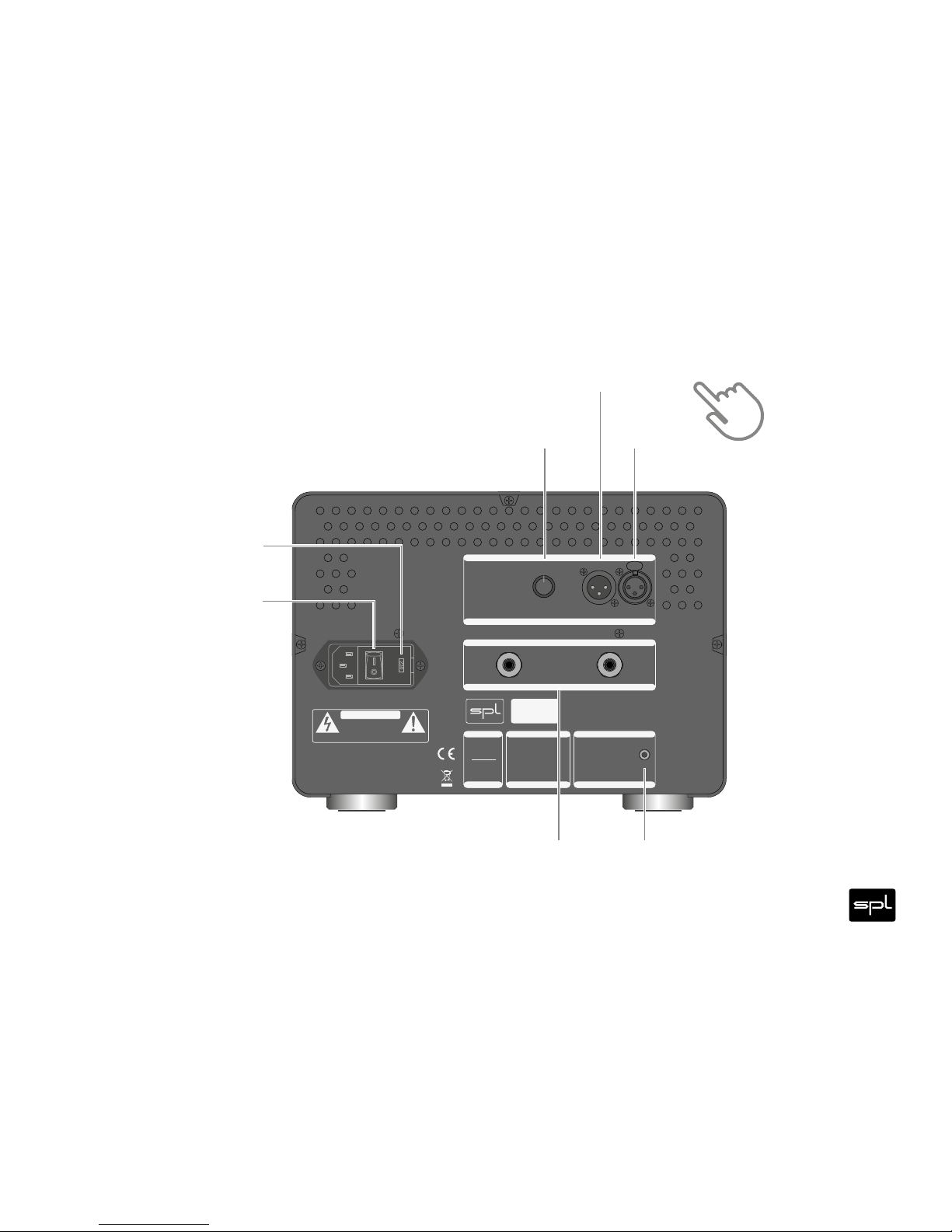
XLR WIRING:
Pin 1 = GND
Pin 2 = Hot (+)
Pin 3 = Cold (–)
Minimum Load:
2Ω
Made in Germany spl.audio
~ 115V AC / ~230V AC, 50Hz / 60 Hz, P max . 1375VA
INPUT
THRU INPUT
TRIM
INPUT
AMP CTL/12V TRIGGER
Connect to
AMP CTL o utput of
SPL Preamplifie r/DAC
for remote power on/off
OR
Use 12 V Trigger
SPEAKER OUTPUT
SPEAKER OUTPUT
+ –
Serial
Number Performer
m1000
AMP CTL/12V TRIGGER
VOLTAGE SELECTION
VOLTAGE SELECTION
230V AC:
T 6.3 A
L 250 V
115V A C:
T 12.5 A
L 250 V
FUSE
FUSE
0
-
5
.
5
-
5
-
4
.
5
-
4
-
3
.
5
-
3
-
2
.
5
-
2
-
1
.
5
-
1
-
0
.
5
Welcome
and thank you for choosing the Performer m.
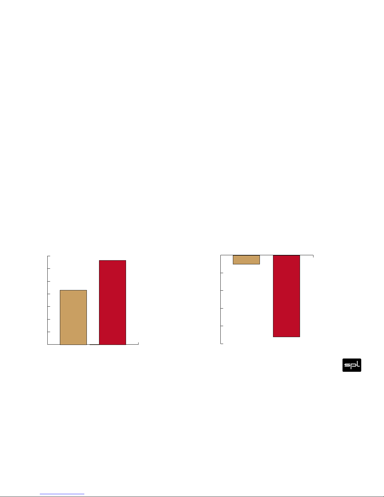
The Performer s is the big brother of the highly acclaimed Performer s and delivers W into ohms,
W into ohms and W into ohms with ease.
VOLTAiR technology is what we also call the SPL V Rail Technology within the Professional Fidelity series. This
makes the Performer m an outstandig device in terms of dynamic range, signal-to-noise ratio and headroom
delivering an exceptional sound experience with invincible serenity, transparency and realness.