2
Welcome
and thank you for choosing the Performer s.
The Performer s amplifier is an ultra-compact power amplifier that delivers x W to ohms loudspeak-
ers. In bridge mode it delivers W into or ohms.
VOLTAiR technology is what we also call the SPL V Rail Technology within the Professional Fidelity series. This
makes the Performer s an outstandig device in terms of dynamic range, signal-to-noise ratio and headroom
delivering an exceptional sound experience with invincible serenity, transparency and realness.
Performer
s800
Stereo Power Amplifier
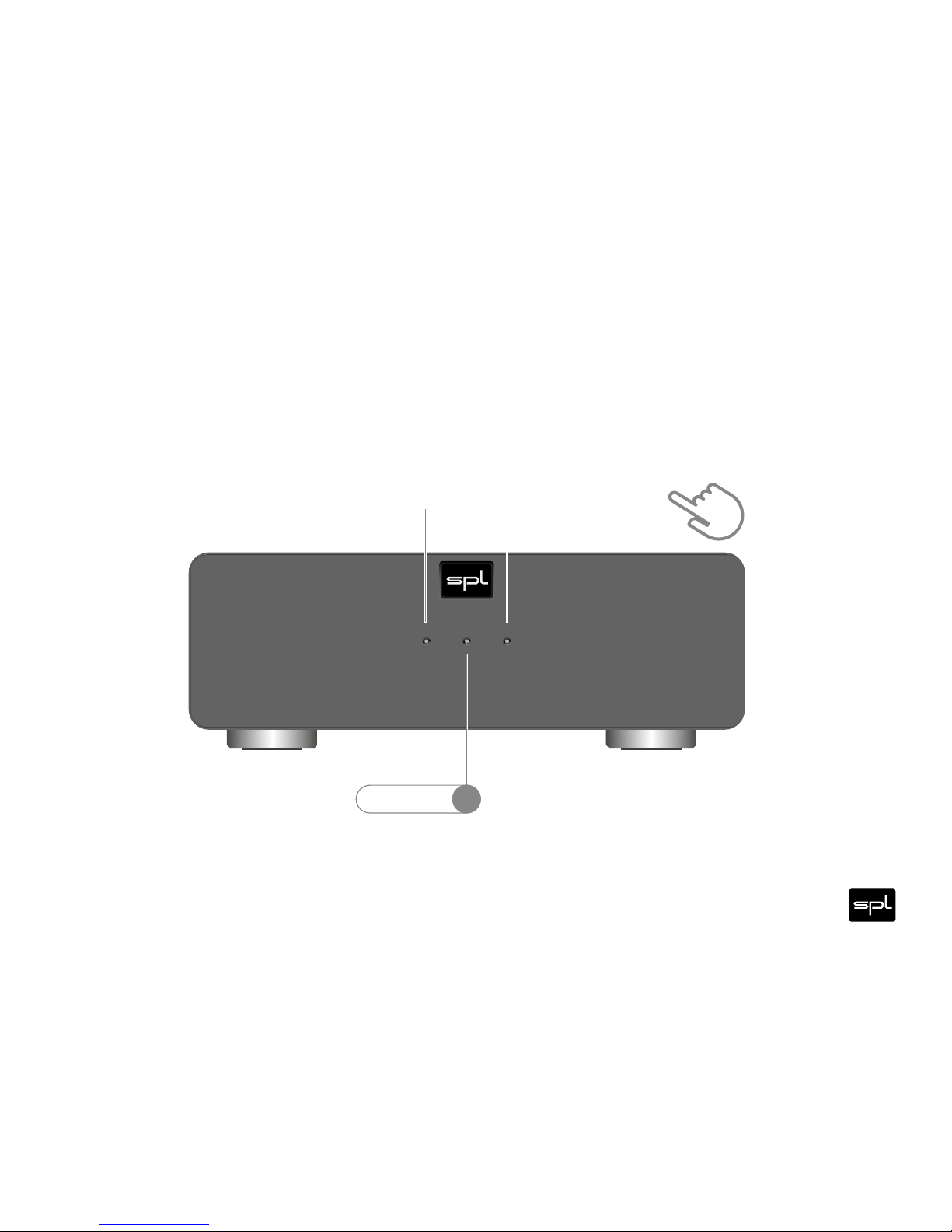
PWRPROTECT TEMP
VOLTAiR
120V DC Audio R ail
Voltage Selection:
Fuse:
1. Remove Fus e Holder
2. Excha nge Fuses
3. Flip Ove r 4. Reinstal l
AVIS: RISQ UE DE CHOC ÉLEC TRIQUE • NE PA S OUVRIR
RISK OF ELE CTRIC SHOCK
DO NOT OPEN
CAUTION XLR WIRING
Pin 1 = GND
Pin 2 = Hot (+)
Pin 3 = Cold (–)
Minimum Load: 4ΩMinimum Load: 4Ω
Minimum Load: 8Ω
Serial
Number
Made in Germany
~ 115V AC / ~230V AC, 50Hz / 60 Hz, P max. 855 VA
Mono
3,5mm
Jack
INPUT L
INPUT L
AMP CTL
AMP CTL
Connect to SP L
Preamplifier/DAC
AMP CTL output
for remote
power on/off.
INPUT R
INPUT R
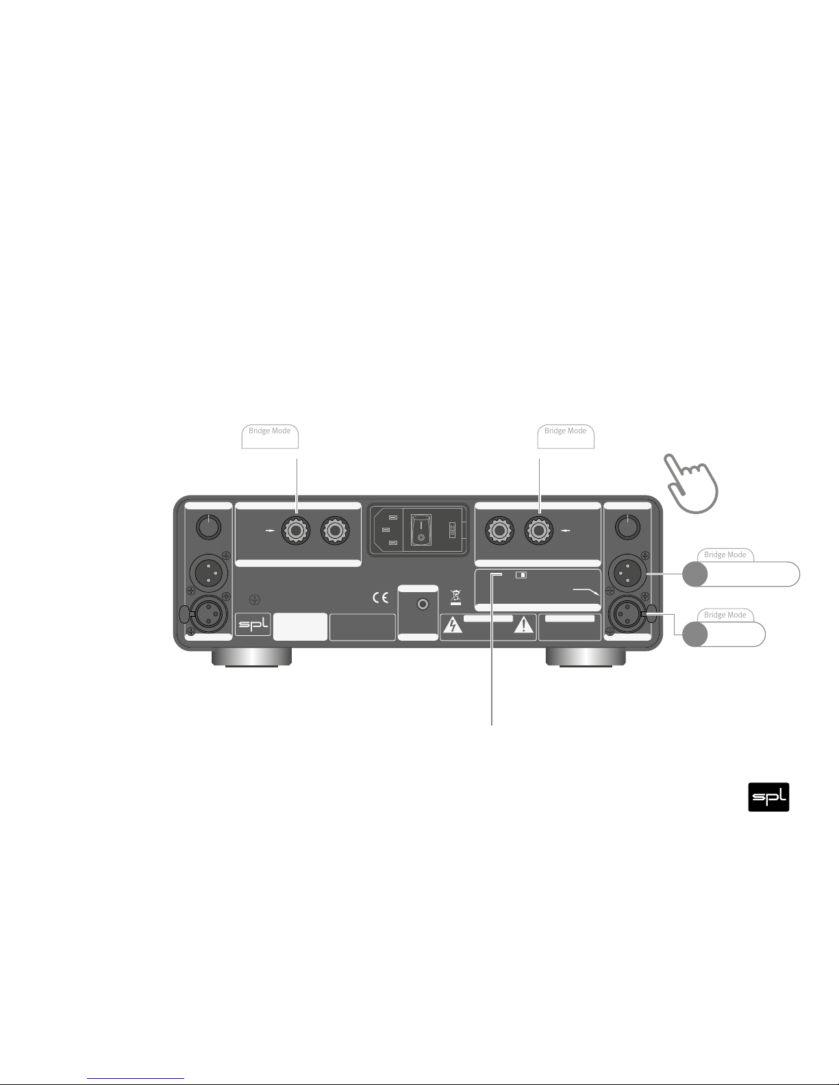
SPEAKER OUTPUT R | BRIDGE MODE (–)
SPEAKER OUTPUT R | BRIDGE MODE (–)
SPEAKER OUTPUT L | BRIDGE MODE (+)
SPEAKER OUTPUT L | BRIDGE MODE (+)
BRIDGE MODE
+–
–
– +
0
-
5
.
5
-
5
-
4
.
5
-
4
-
3
.
5
-
3
-
2
.
5
-
2
-
1
.
5
-
1
-
0
.
5
T
R
I
M
T
H
R
U
T
H
R
U
I
N
P
U
T
I
N
P
U
T
0
-
5
.
5
-
5
-
4
.
5
-
4
-
3
.
5
-
3
-
2
.
5
-
2
-
1
.
5
-
1
-
0
.
5
T
R
I
M
230V AC: T 4 A L 250 V
115V AC: T 8 A L 250 V
Performer
s800
BRIDGE MODE
In Bridge Mode
INPUT R is not
used.
In Bridge Mode
use INPUT L
only.
Note: Trims are deactivated
+
BRIDGE MODE
BRIDGE MODE
ONOFF