Splash Lab TSL.960 Maintenance and service guide
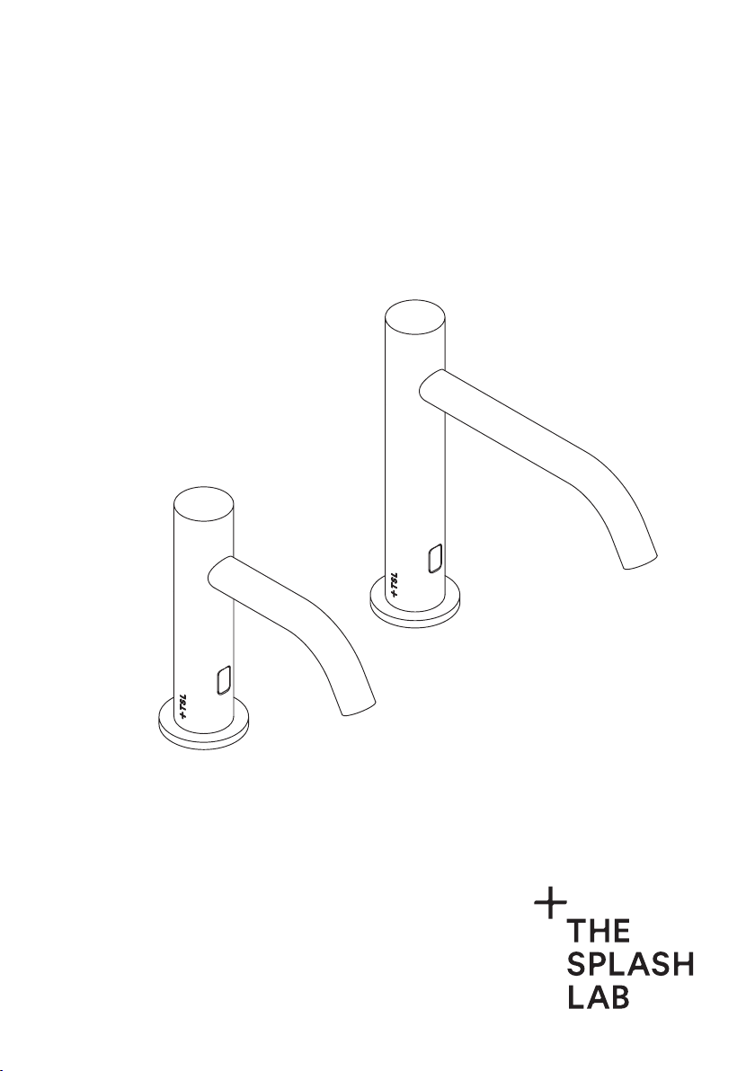
TSL.960 / TSL.990
deck mounted sensor tap
installation + maintenance

3 Safety and Warnings
4 Box Contents
5 Diagram
6 Technical Data
8 Before You Install
9 Technical Drawing
11 How To Install
15 Commissioning & Operation
16 Troubleshooting
17 Cleaning
18 Maintenance
19 Warranty
Back Cover Contact Details
contents
2TSL.960 / TSL.990 MANUAL

TSL.960 / TSL.990 MANUAL 3
For more information contact:
Tel: +44 (0)161 482 7000
Email: technical@thesplashlab.com
Read and save these instructions
WARNING !
To reduce the risk of fire, electric shock or injury to persons, observe the following:
+ Use this unit only in the manner intended by the manufacturer. If you have
questions, contact the manufacturer (see back page for more details).
+ Ensure plumbing is installed correctly before activating water supply.
+ All plumbing is to be installed in accordance with applicable codes
and regulations.
TSL.960 / TSL.990
4TSL.960 / TSL.990 MANUAL
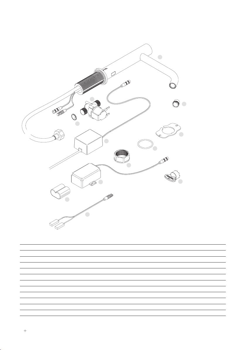
box contents
1
3
4
2
5
7
8
10
11
12
9
6
TSL.960.ELE TSL.990.ELE TSL.960.BAT TSL.990.BAT
1Tap assembly - - - -
2Inline filter / strainer TSLP.08530015 TSLP.08530015 TSLP.08530015 TSLP.08530015
3Solenoid valve TSLP.120030 TSLP.120030 TSLP.120030 TSLP.120030
4Mains power suply unit TSLP.270066 TSLP.270066 - -
5Battery - - TSLP.270030 TSLP.270030
6Battery holder - - TSLP.270029 TSLP.270029
7Backnut TSLP.900.020 TSLP.900.020 TSLP.900.020 TSLP.900.020
8Base O-ring TSLP.104 TSLP.104 TSLP.104 TSLP.104
9Anti-rotation plate TSLP.900.000 TSLP.900.000 TSLP.900.000 TSLP.900.000
10 Aerator - 1.89lpm - Spray pattern TSLP.260063 TSLP.260063 TSLP.260063 TSLP.260063
11 Solenoid connector cable TSLP.120032 TSLP.120032 TSLP.120032 TSLP.120032
12 Aerator key TSLP.260050 TSLP.260050 TSLP.260050 TSLP.260050
TSL.960 / TSL.990 MANUAL 5
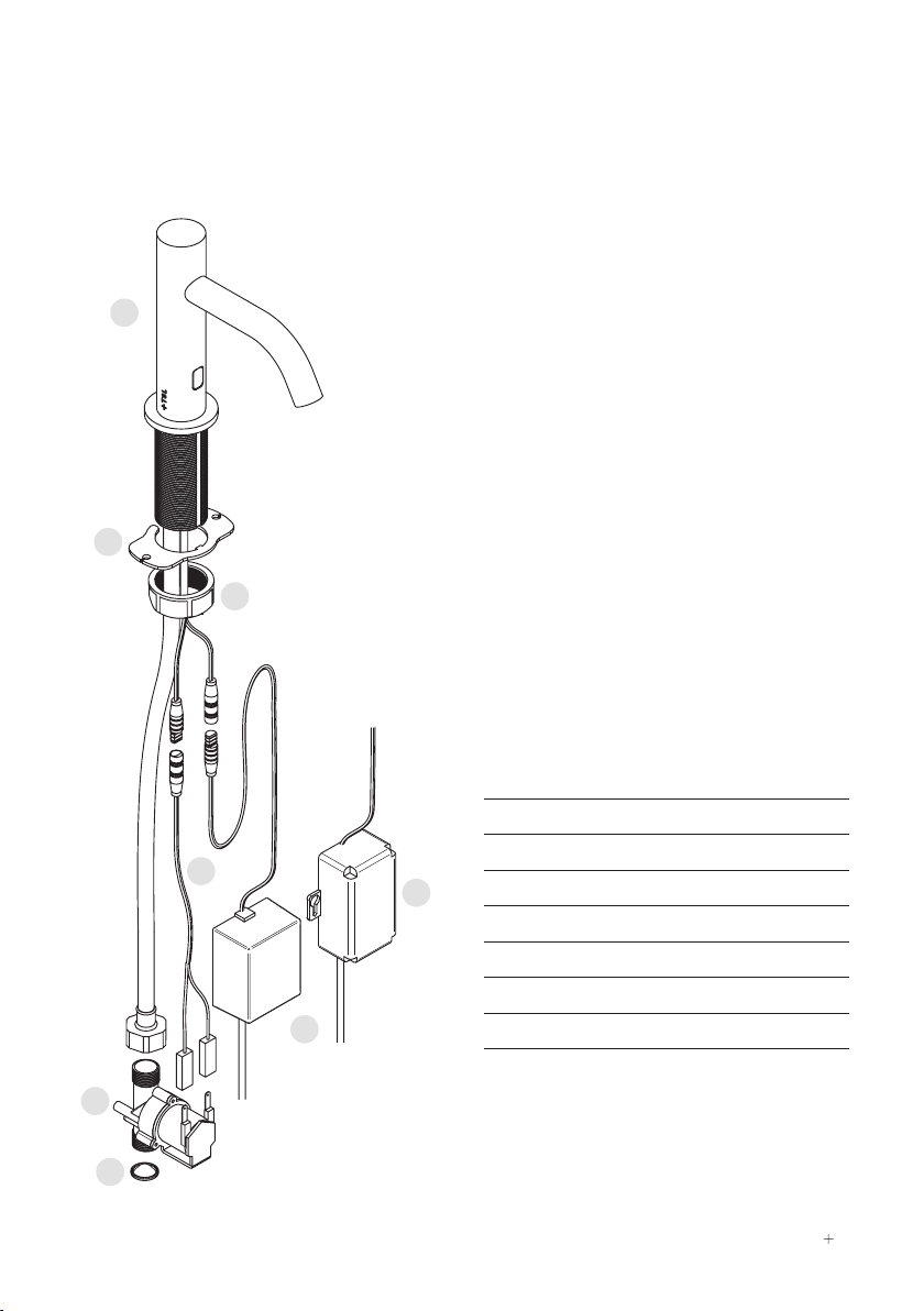
diagram
1 Tap assembly
2 Anti-rotation plate
3 Backnut
4 Solenoid valve
5 Inline filter / strainer
6 Solenoid connector cable
7 Mains power supply unit
8 Battery holder
1
3
4
2
5
7
8
6

6TSL.960 / TSL.990 MANUAL
technical data
Overview
The TSL.990 is a stainless steel deck mounted sensor tap, available in a variety of
coloured finishes, with a sleek and minamalist design.
Codes Power Finishes
TSL.990.CS.BAT Battery Brushed Stainless Steel
TSL.990.CP.BAT Battery Brushed Copper
TSL.990.BK.BAT Battery Brushed Black
TSL.990.BR.BAT Battery Brushed Brass
TSL.990.BZ.BAT Battery Brushed Bronze
TSL.990.CS.ELE Mains Brushed Stainless Steel
TSL.990.CP.ELE Mains Brushed Copper
TSL.990.BK.ELE Mains Brushed Black
TSL.990.BR.ELE Mains Brushed Brass
TSL.990.BZ.ELE Mains Brushed Bronze
Light Reflectance Values
Brushed Stainless Steel 58
Brushed Copper 19
Brushed Black 3
Brushed Brass 40
Brushed Bronze 17
Technical Data: Mechanical
Body Material AISI 304 Stainless Steel
Coating Type PVD (colours only)
Weight 1.4Kg
Aerator Cascade flow
Min/Max pressure 0.5 - 7.5 bar
Flow Rates 3.8l/min [0.5gpm]
Also available as optional extras:
1.35l/min [0.35gpm]
1.89l/min [0.5gpm]
Max Hot Water Temperature 60°C

TSL.960 / TSL.990 MANUAL 7
technical data
Technical Data: Electrical
Power Supply (Battery) 6V CR-P2 Lithium Battery
Power Supply (Mains) 100-240V; 1.5A; 50-60Hz PSU.
Output (Max) 6V; 6W max
Power Consumption < 80A
Solenoid Valve 6V
Water Ingress (PSU) IP67
Cable Lengths Connection to sensor cable - 400mm
Connection to fused supply - 1.5m
Technical Data: Sensor
Sensor Type Infra red
Pre-set Sensor Range 120mm
Maximum Sensor Range 250mm
Comfort Delay 2 seconds
Security Time-out 30 seconds
Operating Temperature 0 to 50ºC
Response Time (max) < 300ms
Compliance
WRAS Certificate 2012304
CE PSU conforms to RoHS, REACH, EN15091
BREEAM Qualities for up to 5 credits as part of water
eciency assessment

8TSL.960 / TSL.990 MANUAL
Access Requirements
It is critical all components which require fixing behind the wall are easily accessible at
all times during installation and routine maintenance.
Front access: If the underside of the wash basin is tiled in, or is fixed onto a vanity
unit, a front hatch or panel(s) must be constructed below the wash basin for ongoing
maintenance access.
Access Requirements
1. A pre-mixed water supply is required that complies with the current local
plumbing regulations.
2. A minimum dynamic water pressure of 0.5bar is required for valve to function.
Gravity-fed installations may require the installation of a booster pump to
achieve the optimum operating pressure.
3. All pipework must be flushed through prior to the tap being connected to
ensure all debris is clear and will not enter the tap. Chlorination of the building
system must also be performed prior to connection of the tap.
4. For mains powered taps, a 3A fused power supply is required. If required,
multiple PSUs can be connected to the mains supply if the fuse is upgraded
accordingly.
before you install
!
Caution
+ The TSL.960 / TSL.990 parts must be put together correctly before
installation.
+ All parts must be installed correctly before powering up the system.
TSL.960 / TSL.990 MANUAL 9
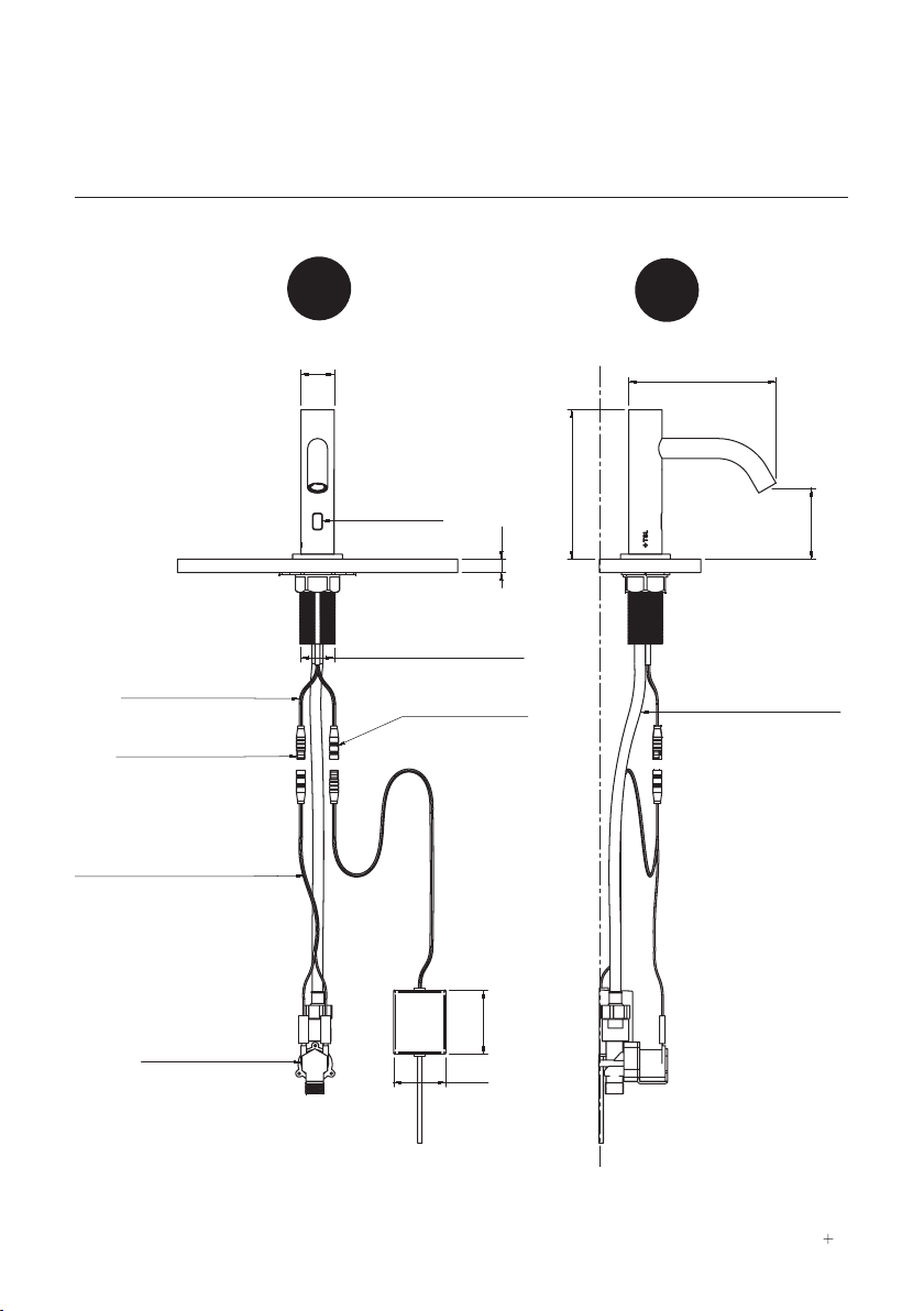
technical drawing
30
12
IR SENSOR
34MM THROUGH HOLE
PSU
58
47
600MM LEAD LENGTH
SENSOR CONNECTOR
TO SOLENOID VALVE
SENSOR CONNECTOR
TO POWER SUPPLY
SOLENOID CONNECTOR LEAD
200MM LEAD LENGTH
SOLENOID VALVE
700MM FLEXIBLE HOSE
135
64
133
TSL.990
SIDE
FRONT
SENSOR CONNECTOR LEAD TO
POWER SUPPLY
10MM MIN 35MM MAX
1
2
" BSP PROVIDED 34MM THROUGH HOLE
SENSOR CONNECTOR CABLE TO
SOLENOID VALVE
IR SENSOR
700MM FLEXIBLE HOSE
POWER SUPPLY
SOLENOID VALVE
135
135
13330
400mm LEAD LENGTH
200mm LEAD LENGTH
600mm LEAD LENGTH
SIDE
FRONT
SENSOR CONNECTOR LEAD TO
POWER SUPPLY
10MM MIN 35MM MAX
1
2
" BSP PROVIDED 34MM THROUGH HOLE
SENSOR CONNECTOR CABLE TO
SOLENOID VALVE
IR SENSOR
700MM FLEXIBLE HOSE
POWER SUPPLY
SOLENOID VALVE
135
135
13330
400mm LEAD LENGTH
200mm LEAD LENGTH
600mm LEAD LENGTH

10 TSL.960 / TSL.990 MANUAL
technical drawing
TSL.960
12
IR SENSOR
34MM THROUGH HOLE
SENSOR CONNECTOR TO
POWER SUPPLY
PSU
58
47
SOLENOID VALVE
SOLENOID CONNECTOR LEAD
200MM LEAD LENGTH
SENSOR CONNECTOR
TO SOLENOID VALVE
175
Ø30
104
175
183
SIDE
FRONT
SENSOR CONNECTOR LEAD TO
POWER SUPPLY
10MM MIN 35MM MAX
1
2
" BSP PROVIDED 34MM THROUGH HOLE
SENSOR CONNECTOR CABLE TO
SOLENOID VALVE
IR SENSOR
700MM FLEXIBLE HOSE
POWER SUPPLY
SOLENOID VALVE
135
135
13330
400mm LEAD LENGTH
200mm LEAD LENGTH
600mm LEAD LENGTH
SIDE
FRONT
SENSOR CONNECTOR LEAD TO
POWER SUPPLY
10MM MIN 35MM MAX
1
2
" BSP PROVIDED 34MM THROUGH HOLE
SENSOR CONNECTOR CABLE TO
SOLENOID VALVE
IR SENSOR
700MM FLEXIBLE HOSE
POWER SUPPLY
SOLENOID VALVE
135
135
13330
400mm LEAD LENGTH
200mm LEAD LENGTH
600mm LEAD LENGTH
TSL.960 / TSL.990 MANUAL 11
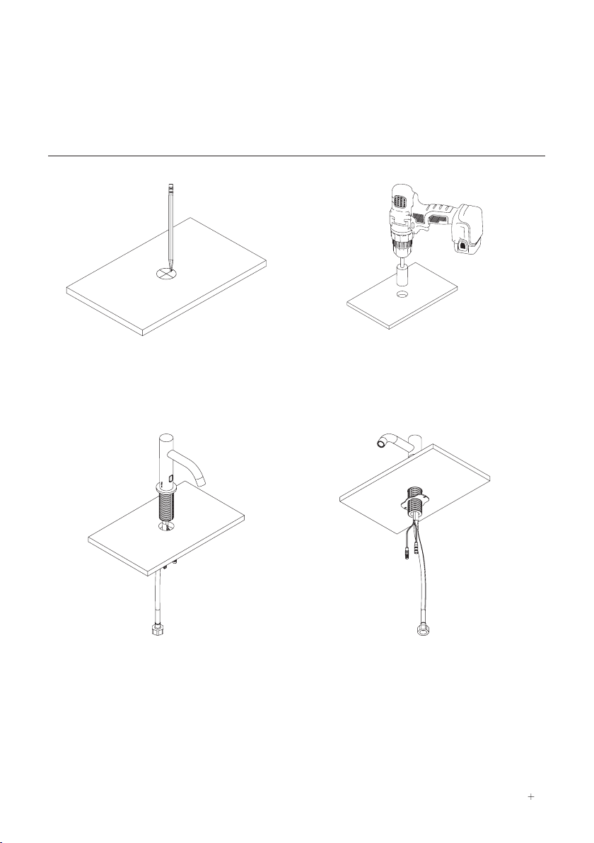
1
Mark tap hole centre onto the surface for
installation.
Tap Installation
2
For countertop fitment, drill 35mm
diameter hole in countertop.
3
Insert the tap through hole in basin or
countertop.
4
Slide the anti-rotation plate and fixing
nut over flexi hose and sensor cable and
onto mounting shank.
how to install

12 TSL.960 / TSL.990 MANUAL
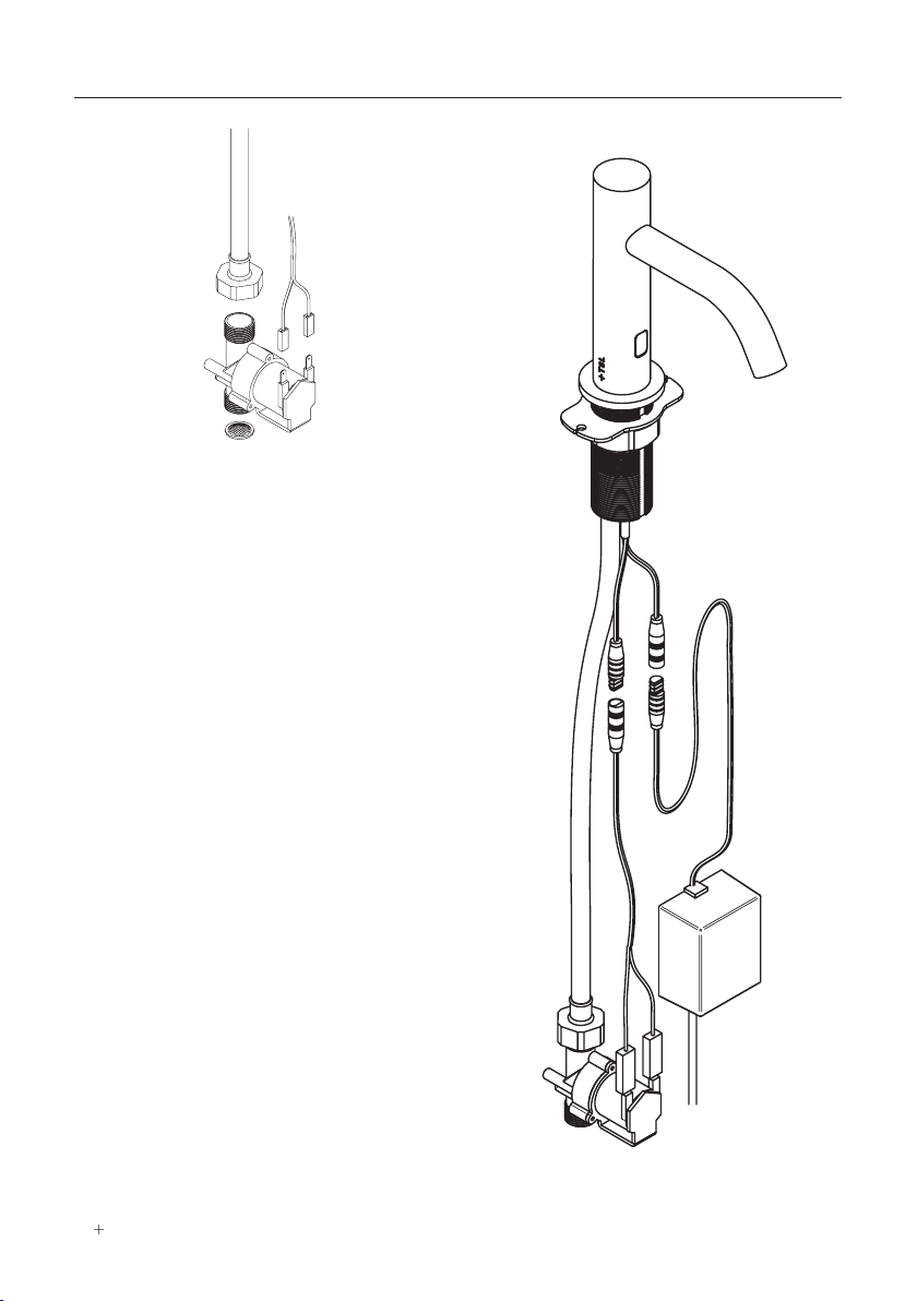
5
Using fixings suitable to your application,
fix the anti rotation plate using the holes
provided.
Tap Installation
6
Slide the backnut over the flexible
hose and sensor leads. Tighten using a
spanner.
7
Position the power supply to the
underside of the unit. Before fixing
into place ensure cables can reach
connector positions.
8
Connect the power supply cable to the
sensor cable.

TSL.960 / TSL.990 MANUAL 13
9
Position the solenoid valve to the
underside of the unit. Before fixing into
place, ensure cables can reach the
connector positions.
Tap Installation
10
Connect the solenoid cable connector
leads to the solenoid valve. observing the
correct polarity of the terminals.
11
Connect the solenoid cable connector to
the sensor connector.
12
Fit the flexible hose nut onto the solenoid
adapter
14 TSL.960 / TSL.990 MANUAL
13
Insert conic filter into inlet side of valve
and connect to water supply. The filter
must be fitted, otherwise the warranty
may be invalid.
Tap Installation
14
Once all nuts are tightened, open the
water inlet and allow water to flow.
WARNING: Ensure all connections are
fully tightened to ensure full seal of the
tap.
15
The product is now ready to be wired into
the spur and tested and commissioned
accordingly.

TSL.960 / TSL.990 MANUAL 15
commissioning
+ Connect the water supply (turn isolation valve on)
+ Turn power supply on and wait 20 seconds
+ Activate the sensor by placing hand within detection range, and water will flow.
Adjusting the sensor range:
The sensor range can be adjusted if required to suit the installation conditions.
1. Disconnect the power supply (battery or mains).
2. Wait a few seconds and reconnect the power supply.
3. Position your hand less than 5cm in front of the sensor whilst the LED flashes.
4. When the LED is contiuously lit (and no longer flashing), position your hand at
the new detection distance.
5. Wait until the LED goes out before removing your hand.
6. When the LED goes out the new detection distance will be set.
operation
The user is to activate the tap by placing their hands within the range of the infra-red
sensor, to cause the solenoid valve to open for a preset time. The valve will close a set
time after the user’s hands have been removed from the detection range.

Problem Cause Solution
Water not flowing Range is too short Increase detection range.
16 TSL.960 / TSL.990 MANUAL
troubleshooting
Range is too long Decrease detection range.
Sensor is dirty or
obstructed. Clean sensor and remove
obstruction.
Tap is in security time-out
mode. Replace batteries or
restore power supply.
Solenoid valve is
incorrectly connected
(polarity reversed).
Reconnect solenoid valve
with correct polarity.
Sensor is detecting
reflections from basin or
another object.
Reduce detection range
or remove object causing
reflection.
Water flow does not stop
when user’s hands are
within range
Debris or scale in solenoid
valve. Remove solenoid and clean
or replace valve.
Cables between PSU and
solenoid are disconnected. Reconnect cables.
Solenoid valve is
incorrectly connected
(polarity reversed).
Reconnect solenoid valve
with correct polarity.
Water supply pressure is
too high. Reduce water pressure.
Slow response time when
opening or closing
solenoid valve
Cable connections loose. Check all connections are
properly fitted together.
Debris or scale in solenoid
valve. Remove solenoid and
clean and replace valve.
Sensor is detecting
reflections from basin or
other object.
Reduce detection range
or remove object causing
reflection.
Water flow reduced Aerator is blocked with
scale or debris. Remove aerator and clean
or replace.
Debris or scale in solenoid
valve. Remove solenoid and
clean and replace valve.

TSL.960 / TSL.990 MANUAL 17
cleaning
+ Take extra care when cleaning decorative surfaces.
+ For surface cleaning of the tap use ONLY soap and water, then wipe dry with a
clean cloth or towel.
+ DO NOT use steel wool or cleaning agents containing alcohol, acid, abrasives or
the like.
+ Use of any prohibited cleaning or maintenance products or substances could
damage the surface of the tap.
+ When cleaning bathroom tiles, the taps should be protected from any splattering
of harsh cleansers.
All grades of stainless steel will stain or discolour if due care and attention is not taken.
The surface must be regularly cleaned to ensure a long service life of the tap.
Use a soft cloth or sponge with a mild solution of soapy water as part of the regular
washroom janitorial routine. Do not use abrasive or cream cleaners as these will
damage the surface finish.
If further information is required, contact The Splash Lab technical team for more
detailed stainless steel care guidelines.

18 TSL.960 / TSL.990 MANUAL
maintenance
1. Shut off the water supply to the tap.
2. Disconnect the solenoid cable from the power supply.
3. Disconnect the solenoid valve from the brass reducing adaptor and the brass
fitting attached to the mains water supply.
4. Remove the filter from the faulty solenoid valve.
5. Re-fit new filter to replacement solenoid valve.
6. Reassemble the parts as shown.
7. Restore the incoming water supply checking there are no water leaks.
8. Reconnect the solenoid cable to the power supply.
Note: the directional flow of water is shown on the solenoid housing with an arrow.

TSL.960 / TSL.990 MANUAL 19
warranty
We believe the future is personal. With a global mindset, we challenge conventional
washroom norms via product innovation to create considered washroom solutions
for corporate, public and hospitality spaces. We use rich raw materials, cutting-edge
automation and considered washroom design to powerfully and positively influence the
lives of people.
Demonstrating our commitment to quality and our belief in the strength of our designs,
we offer the following warranties.
The Splash Lab warrant that its products will be free of manufacturing and material
defects during normal use and environmental conditions as detailed below:
Sensor taps 2 years parts & labour
If a defect is found in normal use, The Splash Lab will, at their discretion, repair, provide
a replacement part or product, or make appropriate adjustments. Damage caused by
accident, misuse, or abuse is not covered by this warranty. Improper care and cleaning
will void the warranty.
Non-operation of the product due to environmental conditions beyond our control,
installation error, incorrect maintenance, water quality, fair wear and tear, incorrect or
inappropriate installation, misuse and abuse is not covered by the warranty.
Proof of purchase (original sales receipt) must be provided to The Splash Lab with all
warranty claims.
The above warranty is valid for goods supplied within the United Kingdom.
For goods supplied outside of the United Kingdom, The Splash Lab will honour the
above stated warranty periods for the parts only.
THE SPLASH LAB DISCLAIM ANY LIABILITY FOR SPECIAL, INCIDENTAL OR
CONSEQUENTIAL DAMAGES.

TSL.960 / TSL.990 EUR REV 1-11/06/21
contact
General information
+44 (0) 161 482 7000
Technical support
technical@thesplashlab.com
For further contact information visit:
www.thesplashlab.com
This manual suits for next models
5
Table of contents
Other Splash Lab Plumbing Product manuals


Popular Plumbing Product manuals by other brands

Sterling
Sterling clearwater Amelio AML10 Fitting Instructions and Parts List

Grohe
Grohe GLOUCESTER owner's manual

Kohler
Kohler Mira Moto Installation and user guide

Everpure
Everpure Dual Temp Faucet specification

Felton
Felton REFLEX FUSION PLUS RFSPCSMCL installation guide

Sunlighten
Sunlighten Signature III Assembly instructions


