Splendide Ariston AS66VX Setup guide

1
AS66VX (Ariston Dryer by Splendide)
Splendide®
120V Automatic Vented Dryer
Training Guide
Part No. TRAINMAN66
TRAINING GUIDE
TECHNICAL EDUCATION
GROUP PRESENTS
The information included in this Repair Manual
may change without notice.
Please see our website
www.splendide.com/service/docs.html
for more information.

2
5 - 7
8 - ?
Organization
Safety Notes and General Servicing Advice 2
Technical Specifications 3
Machine Function 4
Component Description 5-7
Dismantling Instructions 8-17
A. Top Cover 8
B. Control Panel 8
C. Program Timer 9
D. Starting Reley 9
E. Option Switches 9
F. Side Panels 10
G. Front Panel & Air Duct 11
H. Energy Save Thermostats 11
I. Door Switch 12
J. Door Seal 12
K. Door 13
L. Door Hinges 13
M. Front Bearings 13
N. Drive Belt Removal/Replacement 14
O. Capacitor 14
P. Drum Assembly 15
Q. Motor 15
R. Rear Seal 16
S. Heating Assembly & Thermostats 17
Wiring Diagram 19
Technical specifications 3
Machine function
4
louvers

Component Description 5
bottom panel.
bottom panel,

Component Description
6
button
(WHITE DOT)
(PURPLE DOT)
(BLUE DOT)

Component Description 7
Dismantling Instructions
8
Remove the screw on the right hand side
securing the side panel to the front panel.
Lift the locking tabs securing the control
panel to the front panel and lift the control
panel clear of the front panel using care
not to break the locking tabs.
Replace in reverse order.
6.
7.
8.
DISMANTLING INSTRUCTIONS
Ensure that the machine is unplugged.
Beware of sharp edges on metal panels and parts.
•
•
TOP COVER
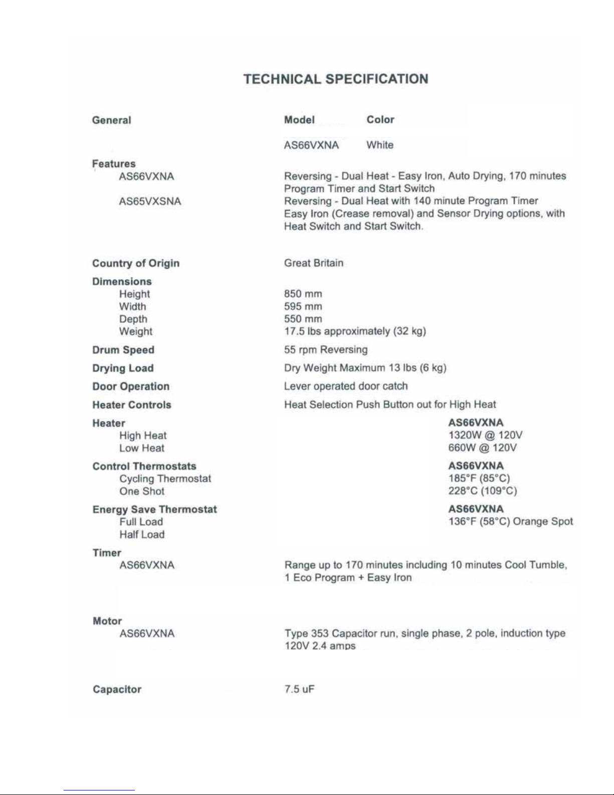
Remove the 2 screws securing the top
cover to the back panel (see right).
Slide the top cover back and lift clear of
the control panel.
B. CONTROL PANEL
Remove the timer knob by pulling straight
out. If you need to use pliers, make sure
to use a shop rag as a buffer so the knob
does not get damaged.
Remove the top cover as in (A).
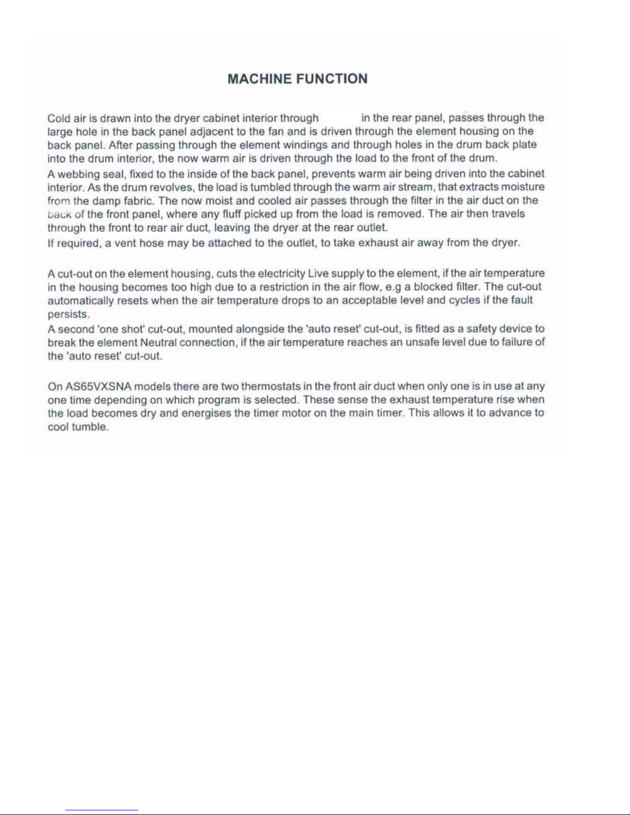
Remove the 2
screws securing
the timer mounting
plate to the control
panel and unclip
the timer mounting
plate from the con-
trol panel. Discon-
nect the wiring to
the option switches and start relay noting
the wire locations.
Disconnect the start relay from the control
panel. See ‘D’.
Remove the 2 screws securing the
control panel to the side panels (top of
control panel).
A.
1.
2.
1.
2.
3.
4.
5.
Dismantling Instructions 9
C. PROGRAM TIMER
Remove the top cover as in (A).
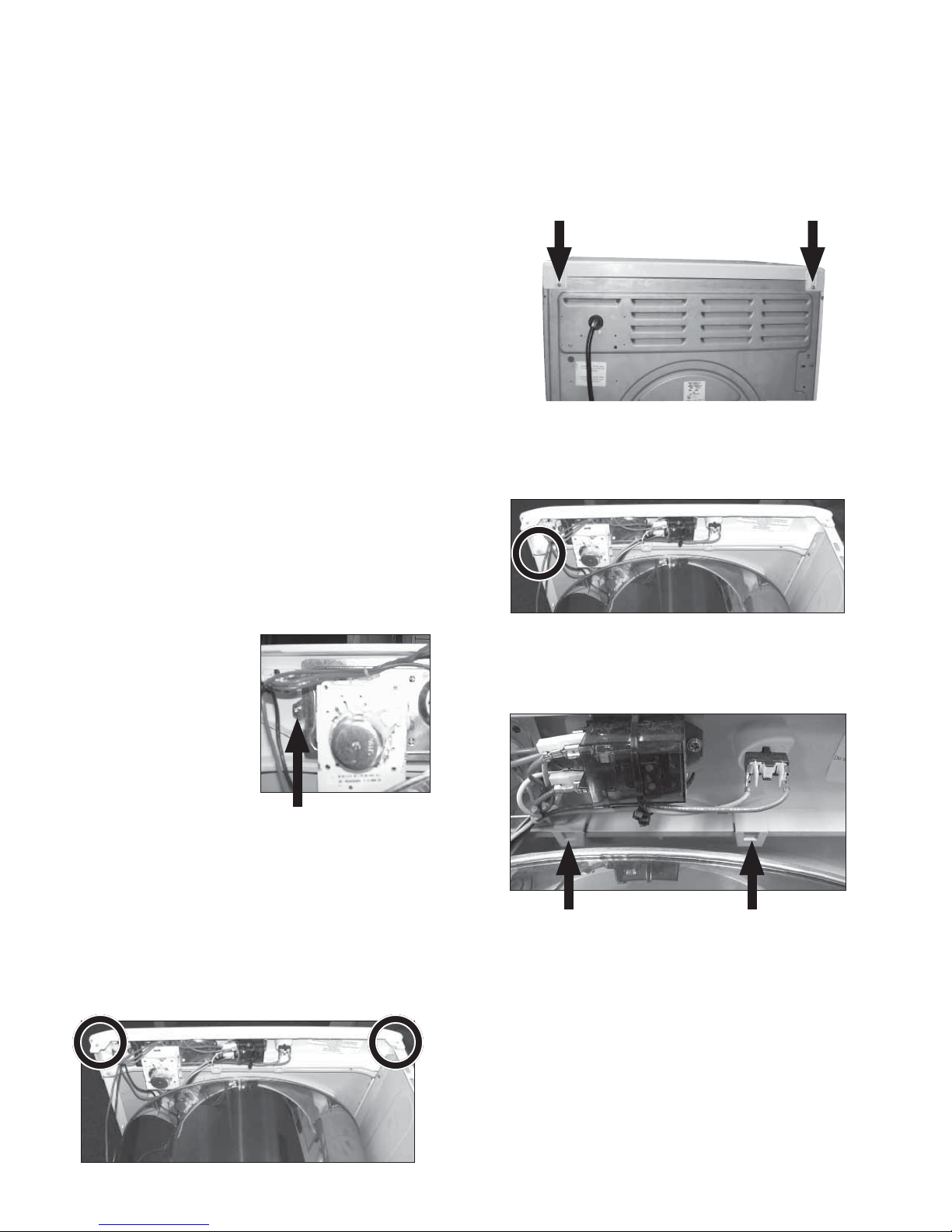
Remove the 2 screws securing the
timer mounting plate to the control
panel and unclip the timer mounting plate
from the control panel.
Remove the 2 screws securing the timer
to the mounting plate.
Note the connections and disconnect the
wiring to the timer.
1.
2.
3.
4.
D. STARTING RELAY
Remove the top cover as in (A).
Cut the wire ties holding the relay to the
control panel.
Remove the 2 screws holding the relay to
the control panel (see right).
Disconnect the wiring to the start relay
noting the connections.
1.
2.
3.
4.
E. OPTION SWITCHES
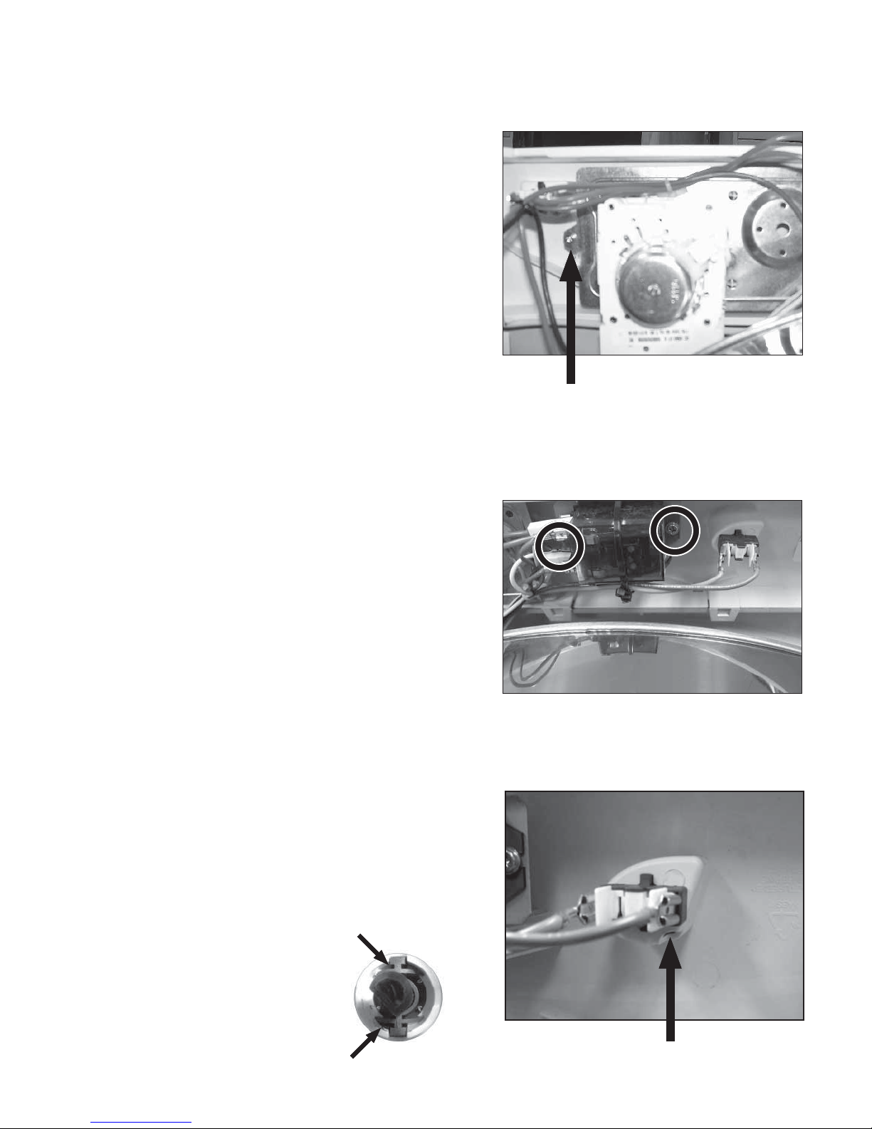
Remove the switch caps by inserting a
small screwdriver into the slot and push-
ing out (see right).
Note the connections and disconnect the
wiring from the switch.
Depress the locking tabs to
remove the switch from the
control panel.
1.
2.
3.

Dismantling Instructions
10
Remove the screws securing the side to
the base panel.
Pull the side panel backward to
disengage from the lugs on the base
panel.
6.
7.
F. SIDE PANELS
Remove the top cover as in (A).
Remove the lower panel by popping the
top edge out then the bottom.
Remove the screw behind the lower
panel.
Remove the screw securing the side
panel to the front panel.
Remove the 4 screws securing the side
panel to the rear panel (see below).
1.
2.
3.
4.
5.
Other manuals for Ariston AS66VX
1
Table of contents
Other Splendide Dryer manuals


Popular Dryer manuals by other brands

Bosch
Bosch WTA79200GB Installation and operating instructions

Amana
Amana W10233410A Use and care guide

Miele
Miele TWH 780 WP operating instructions

Asko
Asko T760 user guide

Alliance Laundry Systems
Alliance Laundry Systems 25 Series Original instructions

Bosch
Bosch Logixx 10 WTB76556GB Instruction manual and installation instructions


Indesit
Indesit IDV 75 instruction manual

Infiniton
Infiniton SD-DG85C manual

BOMANN
BOMANN WT 5019 instruction manual

Alliance Laundry Systems
Alliance Laundry Systems TMB795C Installation

Asko
Asko T793C operating instructions

Kenmore
Kenmore 8041 - 5.8 cu. Ft. Capacity Electric Dryer installation instructions