SPM Airius User manual
1
1
Instructions
www. .com information@itm.com1.800.561.8187

2
3
Technical data subject to change without notice.
ISO 9001 certified. © SPM 2022-08. 72258 B Rev.2
Contents
1. Safety 3
1.1 Special conditions for safe use 3
1.2 Marking and list of standards 3
2. Description 4
3. Technical specifications 5
4. Installation of Airius Ex sensor 6
4.1 Screw installation 6
4.2 Glue installation 8
5. Sensor operation 10
5.1 Reset to factory default 10
5.2 Clear settings via SPM Connect app 10
5.3 Setting up Airius with SPM Connect 11
5.4 Setting up vibration measurements in Condmaster Ruby 12
5.5 Setting up vibration measurements in Condmaster.NET 14
6. Maintenance and service 16
6.1 Battery replacement 16
www. .com information@itm.com1.800.561.8187
2
3
1. Safety
This sensor must only be installed, used and maintained
by competent personnel. Such personnel shall have un-
dergone training that included instruction on the various
types of protection and installation practices, the relevant
rules and regulations, and on the general principles of area
classification. Appropriate refresher training shall be given
on a regular basis (see EN 60079-17).
The installation, use and maintenance of this sensor must
comply with the appropriate European, national and lo-
cal regulations, which may include reference to the IEC
standards IEC60079-14, IEC60079-17 and IEC60079-19.
In addition, particular industries or end-users may have
specific requirements relating to safety (or health) and
these requirements should also be met. Instructions and
specifications issued by the manufacturer must be followed.
Warning – Use only SPM 18425 battery.
Immediately remove the sensor from Ex-hazardous areas if
safety is questioned or compromised. Return the product
to SPM Instrument AB for examination.
For configuring the Airius sensor, only certified mobile
devices are allowed to be used in Ex-hazardous areas.
The batteries are classified as dangerous goods, when
transported. Transportation of batteries must be in full com-
pliance with the appropriate regulatory provisions. UN3090
is applicable for the batteries and UN3091 is applicable
when the battery is contained in the sensor.
1.1 Special conditions for safe use
None.
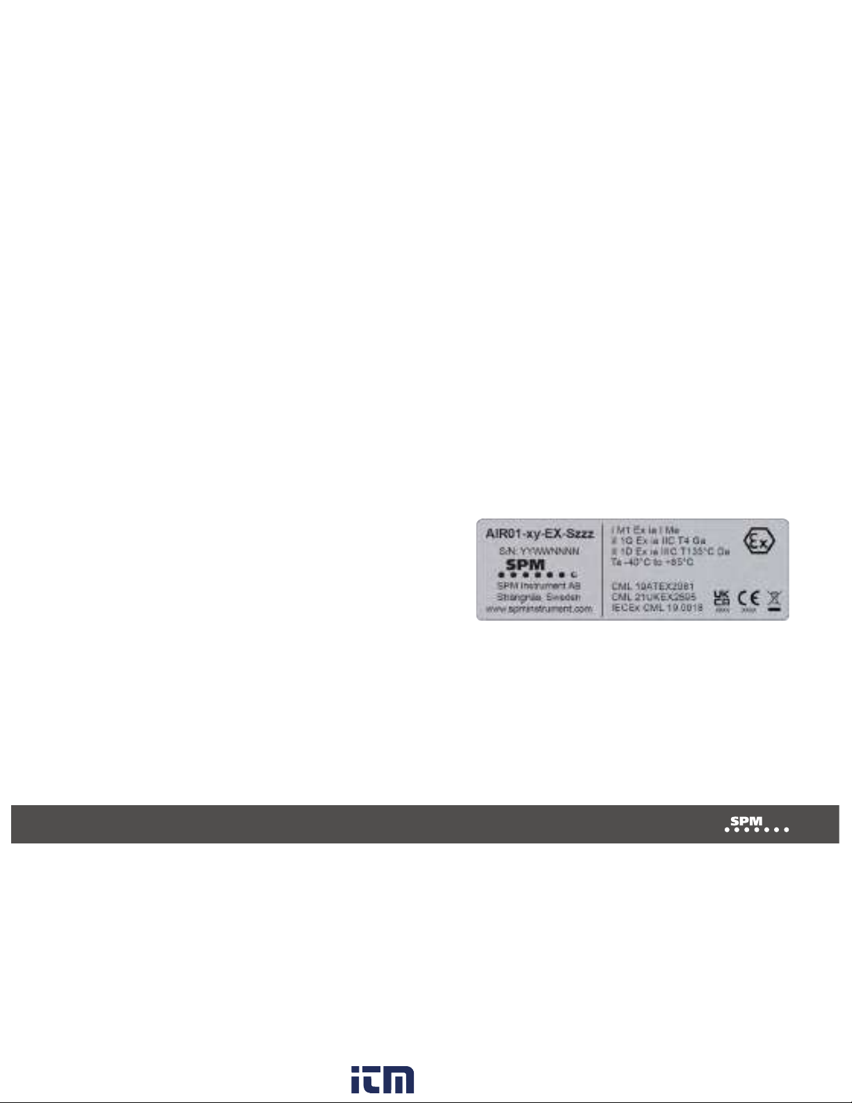
1.2 Marking and list of standards
I M1 Ex ia I Ma
II 1G Ex ia IIC T4 Ga
II 1D Ex ia IIIC T135 °C Da
Ta –40 °C to +85 °C
CML 19ATEX2081
CML 21UKEX2595
IECEx CML 19.0018
Standards are listed in the EU Declaration of Conformity.
Sensor marking.
Battery marking.
www. .com information@itm.com1.800.561.8187

4
5
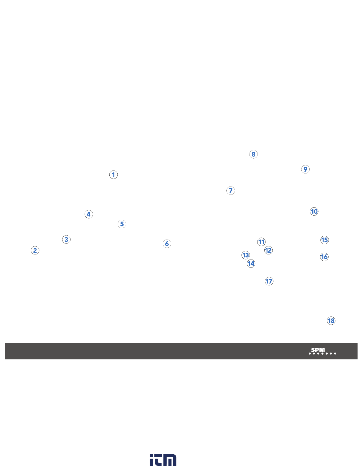
2. Description
The battery-powered wireless sensor AIR01-EX, which ena-
bles wireless condition monitoring in potentially explosive
atmosphere, measures acceleration in three directions,
and temperature. For remote communication, Wi-Fi and
Bluetooth are used. An external push button and three
RGB-LEDs are local user interfaces.
The product enclosure consists of a metal body and an
ESD-protected plastic lid. To enable battery replacement,
the lid is removable. Screw or glue installation on a machine
is performed with an installation foot. Depending on the
installation foot and place of installation, the metal body
may be earthed or unearthed.
There are different versions of AIR01-EX, specified as
AIR01-xy-EX-Szz, where variations do not affect Ex safety.
The letters ‘xy’ denote measurement performance (e.g.
frequency bandwidth) and ‘Szz’ denote variations of op-
erating software.
AIR01-Ex is a member of the Airius family of wireless sensors.
The Airius sensor is compatible with both Condmaster.NET,
the application providing easy access to measurement
data through a user-friendly interface, and the analysis and
diagnostic software Condmaster Ruby.
The SPM Connect app, downloadable for mobile devices,
is used to configure the parameters required for connection
to Condmaster Entity Server (CES) or SPM Cloud.
www. .com information@itm.com1.800.561.8187

4
5
3. Technical specifications
Approvals/Certificates: CE, ATEX, IECEX, UKEX, FCC, Canadian RSS, China
MIIT, Japan MIC, Korean CRM, Taiwan NCC, WiFi Alliance,
Bluetooth SIG
Enclosure: stainless steel body, acid proof; plastic lid, ESD protected
Weight: 215 g
Power supply: replaceable lithium battery, SPM 18425 only
Battery capacity 13 Wh1
Battery shelf life 12 months2
Acceleration measurement: See part numbers:
Range, Resolution
Bandwidth, Resolution
Temperature measurement:
Range –40 °C to +85 °C (–40 °F to +185 °F)
Resolution 0.1 °C
Accuracy +/– 2 °C
Ambient temperatures:
Operational –20 °C to +85 °C (–4 °F to +185 °F)
Ex safety –40 °C to +85 °C (–40 °F to +185 °F)
Storage –40 °C to +85 °C (–40 °F to +185 °F)
Protection class: IP69
Relative humidity: 0 to 100% (non-condensing)
Wi-Fi: 802.11 b/g/n, 2412 MHz-2472 MHz, 19.9 dBm
Wi-Fi Security: WPA/WPA2 PSK/WPA2 Enterprise (PEAP-MSCHAPv2
and TTLS-MSCHAPv2 without certificates)
Bluetooth: v4.2 BLE, 2402 MHz-2480 MHz, 2.7 dBm
Antenna: Internal PCB antenna only, 3.7 dBi
Installation: Installation foot, glue (Loctite 326 and activator Loctite 7646)
or screw (M4, M6, M8, UNF ¼”)
1Battery cell capacity is 13Wh. Affected by ambient temperature, current profile of load and shelf life above
12 months. Active sensor power consumption increases by Radio (Wi-Fi or BL) low signal strength or high
traffic intensity.
Typical capacity cases:
• Four measurements per day for four years, ±0 to +40 °C, RSSI
≥ −70 dB. Sleeping sensor power consumption is increased by
high ambient temperature.
• Eight years of sensor deep sleep only, ±0 to +40 °C.
The sensor calculates the remaining number of measurements
based on; time from manufacture, time spent in configuration
mode (BL), time between measurements, ambient temperature
and Wi-Fi signal strength (RSSI).
2Battery Shelf Life is 12 months. After 12 months the battery ca-
pacity might be reduced. Ongoing long-time tests are performed,
with the aim to prove an expected longer battery shelf life.
Part numbers
AIR01-01-EX Airius Ex sensor, 2/4/8 g, 16 bits,
10-1000 Hz, 800/1600 lines
AIR01-10-EX Airius Ex sensor, 2/4/8/16 g, 16 bits
10-5000 Hz, 800/1600 lines or
Airius Ex sensor, 10/20/40 g, 20 bits
2-1000 Hz, 800/1600 lines
Accessories
18470 Installation kit (installation foot, M4 screw,
M4 washer, M6 screw)
18471 Installation kit (installation foot, M8 screw)
18466 Installation foot, glue installation
Spare parts
100065 Ex spare part kit (battery, lid with
gasket, 4 pcs M3x8 screws)
www. .com information@itm.com1.800.561.8187
6
7
4. Installation of Airius Ex sensor
Installation must only be performed by competent
personnel. There are two methods for installing Airius Ex
sensors, either by screw installation or glue installation.
Position the sensor in such a way that it can optimally
perform measurements while having good Wi-Fi signal
strength.
4.1 Screw installation
1. Drill a screw hole where the sensor should be
placed.
2. Drill a counterbore with 30 mm diameter on the
machine.
3. Align the longest flat side of the installation foot
with the x-axis of the intended measurement direc-
tion.
4. Screw the installation foot onto the machine. See
table for screw torque.
5. Screw the sensor onto the installation foot. See table
for sensor torque.
6. Check that the marking of the sensor aligns with the
intended measurement directions. If the markings
are not aligned with the intended measurement
directions, adjust the installation foot.
NOTE: There are markings for z, x and y on the
sensor, indicating the directions of the measurement.
www. .com information@itm.com1.800.561.8187

6
7
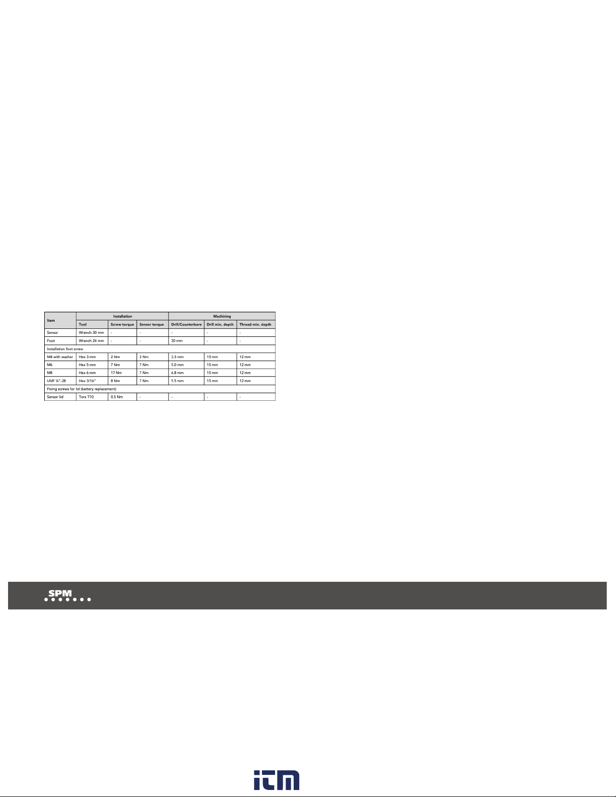
1 2 3
4 5 6
Ø 30 mm
Sensor torque:
M4 with washer 2 Nm
M6 7 Nm
M8 7 Nm
UNF 1/4” 7 Nm
Screw torque:
M4 with washer 2 Nm
M6 7 Nm
M8 17 Nm
UNF 1/4” 8 Nm
www. .com information@itm.com1.800.561.8187

8
9
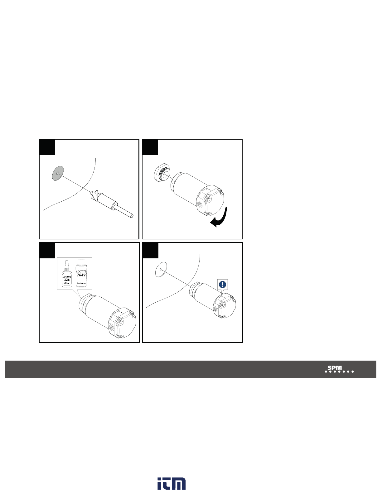
4.2 Glue installation
1. Drill a counterbore with 30 mm diameter on the
machine where the sensor should be placed.
2. Screw the sensor onto the installation foot. Tighten-
ing torque: 7 Nm.
3. Apply glue (Loctite 326) and activator (Loctite 7649)
to the installation foot.
4. Check that the markings of the sensor align with the
intended measurement directions. Press the sensor
onto the flat surface. Hold steady for three minutes.
NOTE: There are markings for z, x and y on the sen-
sor, indicating the directions of the measurement.
www. .com information@itm.com1.800.561.8187
8
9
1 2
3 4
Sensor torque: 7 Nm
Ø 30 mm
www. .com information@itm.com1.800.561.8187

10
11
5. Sensor Operation
LED indication and push-button management are shown
in the functional state diagram to the right.
5.1 Reset to factory default
Press and hold the internal push button while the battery
is reconnected. Factory default clears all settings and
reverts to the software installed during factory production.
5.2 Clear settings via the SPM Connect app
Clear settings continue to use the latest software while all
settings are cleared. For more information, see chapter
‘Setting up Airius with SPM Connect’.
Not configured
Not configured
No server
Button
pressed
On
Fast flash
Slow flash
Off
Button pressed
and hold
From any state
E.g. measure and
send data to server.
Set timer.
Recovered/connected
battery
Bad/disconnected
battery
Configured
Configured
Timer expired
Server available
Exit, button pressed,
20 s timeout or connection lost
www. .com information@itm.com1.800.561.8187

10
11
5.3 Setting up Airius with SPM Connect
1. Download the SPM Connect app via App Store or Google Play.
2. Press and hold the button on the Airius sensor until it lights blue.
3. Open the SPM Connect app.
4. Swipe down to search for a sensor. Choose a sensor in the list (A).
5. Select Configure (B).
6. Choose Wi-Fi from the list and enter a password (C). To connect to a hidden
network, select Enter SSID manually.
7. Choose dynamic (”Obtain IP address automatically (DHCP)”) or static IP
addressing (D). If static, enter IP address.
8. Choose SPM Cloud or Condmaster Entity Server (CES), depending on
the method of connection. Enter server address, server port and whether SSL
should be activated or not (E).
9. To create a password for the sensor, select Password protect device (F).
10. Select APPLY (G).
11. To perform a function and connection test, press the button on the sensor.
Immediate green flashing means that the sensor works. When the connection
to the server is successful, the sensor flashes green. The number of flashes
corresponds to the Wi-Fi signal strength (1-3). If the connection is unsuccessful,
the sensor lights red.
12. Follow the steps in ‘Setting up vibration measurements in Condmaster
Ruby’ or ‘Setting up vibration measurements in Condmaster.NET’, depending
on your software.
www. .com information@itm.com1.800.561.8187

12
13
5.4 Setting up vibration measurements in Condmaster Ruby
1. Go to the Graphical Overview tab and select View as tree in the ribbon bar.
2. Expand Components.
3. Right-click Components, choose Create and select Component.
4. Enter component number and name.
5. Select Save.
6. Right-click the created component, choose Create and select Measuring point.
7. Enter Measuring point number and name.
8. Choose a vibration measurement technique (Vibration, 2 or 3 channel vibration, or ISO 10816) and select Add.
9. Choose Online under Instrument, choose settings as desired and select OK.
10. Go to the Online tab, select the Airius sensor and direction (z, x or y) under Address. Select OK.
11. Go to the Settings tab, name the assignment and edit the settings as desired.
12. For settings regarding conditions and filtering of results, go to the Online Advanced tab.
13. Go to RPM and enter fixed or variable speed (as a global value).
14. Select Save.
For further information regarding these steps, see chapter ’Setting up measuring assignments for Airius Ex
vibration sensors’ in the ’Condmaster Ruby User guide’ (72261).
www. .com information@itm.com1.800.561.8187

12
13
www. .com information@itm.com1.800.561.8187

14
15
5.5 Setting up vibration measurements in Condmaster.NET
1. Open Condmaster.NET and log in. If required, choose a database.
2. Select Settings.
3. Select Components.
4. Select Add.
5. Enter the component details.
6. Select Create.
7. Select Measuring points.
8. Select Add.
9. Enter the measurement point details.
10. Select Create.
11. Enter a name for the measuring assignment.
12. Choose a sensor under Measuring device.
13. To edit measuring interval, operational hours or measuring range for the Airius sensor, select Edit device settings.
14. Select the axes (z, x, y) to be measured.
15. Choose frequency range.
16. Choose spectrum unit.
17. Set alarm limit for each condition parameter that should have an alarm limit.
18. Select Create.
For further information regarding these steps, see chapter ’Getting started’ in the ’Condmaster.NET User guide’ (72239).
www. .com information@itm.com1.800.561.8187
14
15
www. .com information@itm.com1.800.561.8187

16
17
6.1 Battery replacement
0.5 Nm
6. Maintenance and service
The installed sensor may only be maintained, inspected
or repaired by competent personnel.
Immediately remove the sensor from Ex-hazardous areas
if the safety is questioned or compromised. Return the
product to SPM Instrument AB for examination.
Battery assembly, lid and screws may be replaced. All
other repair measures may only be performed by SPM
Instrument AB. To clean the external surfaces of the
product, wipe the enclosure with a damp cloth and mild
detergent. Always take necessary ESD precautions when
the sensor is maintained or repaired.
1. Loosen the screws and remove the lid.
Note: Observe the position of the lid.
2. Remove the battery and disconnect the plug.
Note: If the battery is stuck, carefully pull the cables
or use a long thin hook.
3. Connect the plug and insert the new battery.
Warning: Use only SPM battery.
4. Carefully press down the plug and cables below the
top of the battery.
5. Clean the surfaces between the lid and the sensor body.
6. Screw on the new lid with new screws. Tightening
torque: 0.5 Nm.
Note: Ensure the lid protrusion is above the battery.
7. Ensure the battery health indicator is aware of
the battery replacement. For more information, see
chapter ’Setting up measuring assignments for Airius
Ex vibration sensors’ in the ’Condmaster Ruby User
guide’ (72261) or ’Getting started’ in the
’Condmaster.NET User guide’ (72239), depending on
your software.
www. .com information@itm.com1.800.561.8187

16
17
This product must be disposed as electronic waste and is marked with a crossed-out wheeled bin symbol in order to prevent
it being discarded with household waste.
When the life cycle of the product is over You can return it to Your local SPM representative for correct treatment,
or dispose it together with your other electronic waste.
www. .com information@itm.com1.800.561.8187
This manual suits for next models
3
Table of contents
Other SPM Accessories manuals

Popular Accessories manuals by other brands

Samsung
Samsung SIP-1201DD user manual

Sloan
Sloan SJS-1450 Installation & operating instruction manual

Haltian
Haltian thingsee AIR User and installation guide

RTK
RTK MV 5351 Series Installation and operating instructions

Tecsis
Tecsis P3427 instruction manual

PCB Piezotronics
PCB Piezotronics ICP 356A26 Installation and operating manual


