Spotlight FresneLED 250 TW User manual

Manuale utente - User manual
FresneLED 250 TW
cod. FN LED 250 TW DMX
FresneLED 250 TW
1
2
3
4
5
9
7
6
10
8
2
ATTENZIONE: Prima di usare questi apparecchi,
leggere attentamente le istruzioni che seguono.
Spotlight srl non potrà essere ritenuta responsabile di
danni derivanti dalla non osservanza di dette istruzioni.
SAFETY WARNING: Before using this product,
read the present instructions carefully.
Spotlight srl will not be responsible for damage
resulting from instructions not being followed.
ITALIANO: Pag. 3 ENGLISH: Pag. 10
Fig. 1
FresneLED 250 TW
423
265 415
CONSOLE
DMX OUT
DMX OUT
DMX IN
DMX OUTDMX IN DMX IN
MASTER EFFECT
IR
MANUAL
SLAVE
OUT
IN OUT
IN OUT
SLAVE
3
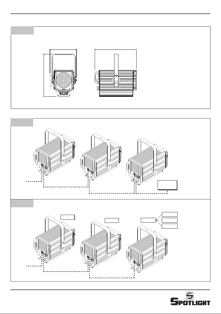
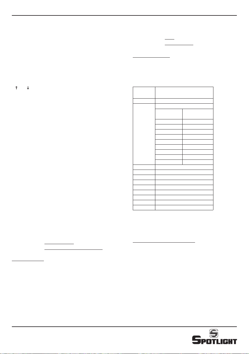
Installazione con segnale DMX - DMX connection
Dimensioni (mm) e pesi - Dimensions (mm) and weight
Fig. 2
Fig. 3
Kg. 9
Installazione MASTER/SLAVE - MASTER/SLAVE configuration
Fig. 4
FresneLED 250 TW
4
DESCRIZIONE GENERALE
DESCRIZIONE DEL PROIETTORE
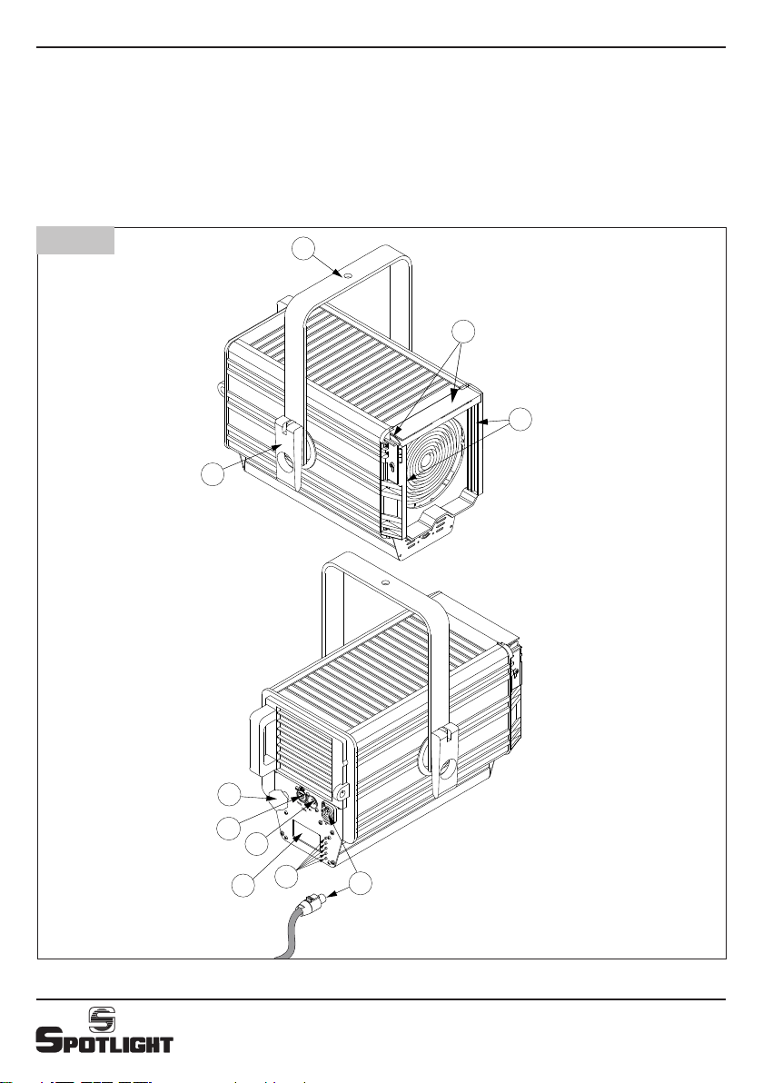
Riferendosi ai disegni di pag. 2 (Fig. 1)
① Staffa di sospensione
②Maniglia per regolazione inclinazione faro
③Guide portaccessori
④Tettuccio e molla fermaccessori
⑤Pomello regolazione zoom
⑥DMX THRU / OUT
⑦DMX IN
⑧Display
⑨Pulsanti display
⑩Alimentazione IN (connettore Powercon)
INDICAZIONI GENERALI
Il proiettore in Vs possesso risponde alle direttive
73/23/CEE in quanto conforme alle norme EN 60598-1
e EN 60598-2-1.
La targhetta che è sistemata sul fianco del proiettore,
contiene le seguenti informazioni:
•Modello
•Tensione di alimentazione in V
• Potenza in W
• Indice di protezione IP
• Massima temperatura ambiente ammissibile in °C
INSTALLAZIONE
• Il proiettore è progettato esclusivamente per impiego
professionale.
• Si prega di prestare la dovuta attenzione alle note
riportate sull’etichetta dell’apparecchio.
• Ricordarsi di collegare la fune di sicurezza se previsto
dalle norme di sicurezza locali.
• ll proiettore può essere usato sia sospeso sia montato
su cavalletto.
CONNESSIONI ELETTRICHE
Il vostro faro è stato progettato per una tensione di
alimentazione da 100 a 240V, 50/60 Hz.
Prima e durante l’installazione osservare le seguenti norme:
• Vericare sempre l’efcienza del collegamento a terra
della linea in uso.
• Vericare che la tensione di alimentazione corrisponda
a quella dell’apparecchio
• L’apparecchio è previsto per uso all’interno (IP 20):
pertanto deve essere protetto dall’umidità e dalla
pioggia se usato in condizioni diverse.
• L’apparecchio NON può essere collegato a un dimmer.
Sulla parte posteriore del faro sono collocati i
seguenti connettori:
•di alimentazione (dotato di blocco di sicurezza
antisgancio):
- 1 connettore Powercon BLU, per ingresso (POWER IN)
•dicontrollo:
- 1 connettore a 5 poli XLR maschio per l’ingresso del
segnale DMX 512 (DMX IN) o seriale (Master/Slave)
- 1 connettore a 5 poli XLR femmina per la trasmissione
del segnale DMX 512 al faro successivo (DMX THRU/
OUT) o seriale (Master/Slave)
PUNTAMENTO
Tramite la maniglia laterale ②si può allentare il
bloccaggio del faro e modicare la sua inclinazione. Lo
stesso si può fare per la rotazione sull’asse verticale,
facendolo ruotare sul perno di aggancio.
MANUTENZIONE
Sottoporre il faro a revisione almeno una volta all’anno per
controllare l’integrità delle parti elettriche e meccaniche
ed eventualmente per l’aggiornamento del software.
A tal fine utilizzare solo rivenditori qualificati, a garanzia
di un corretto e completo intervento.
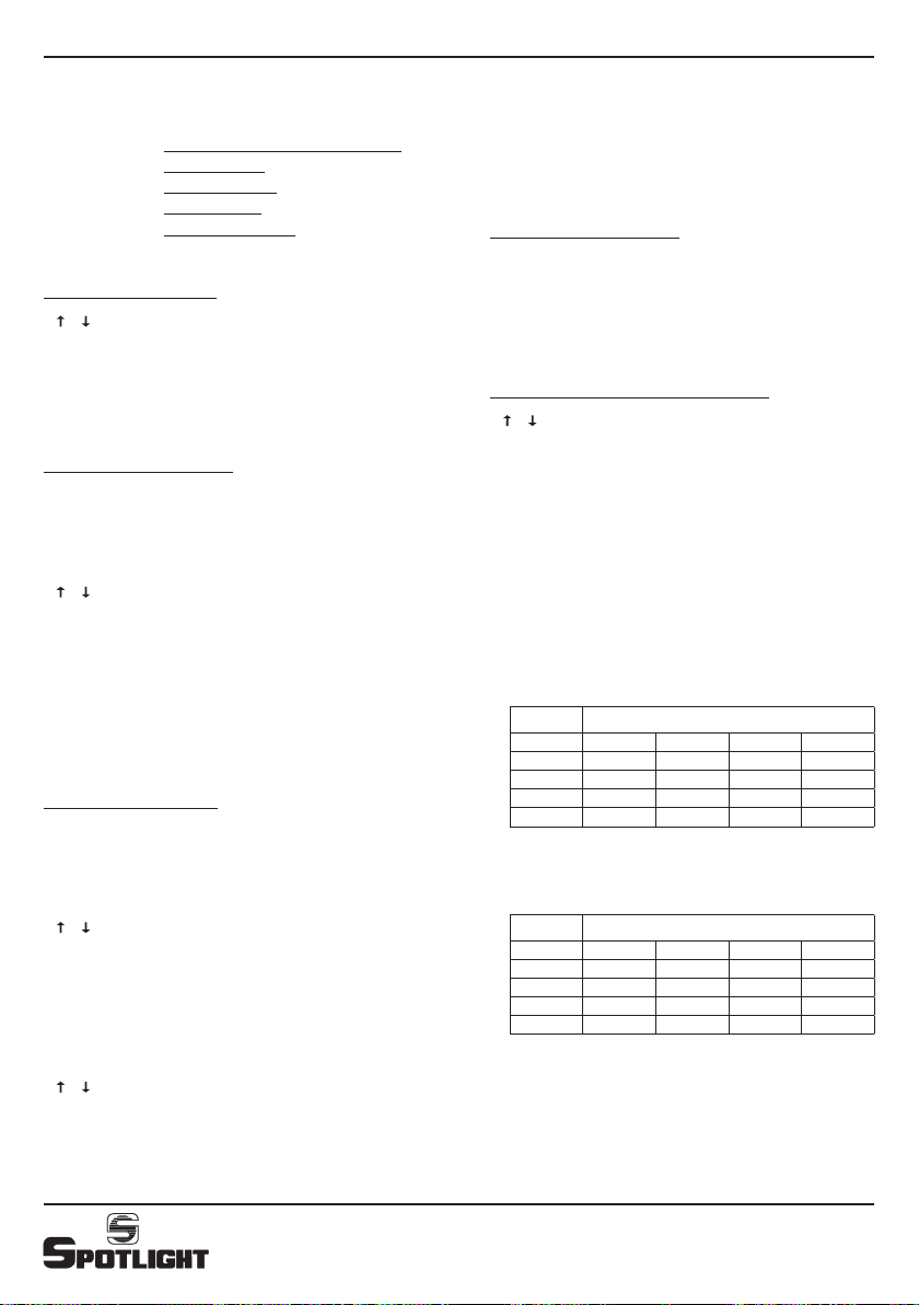
RICICLAGGIO
Il prodotto deve essere riciclato o smaltito
secondo la direttiva 2002/96/CE
ATTENZIONE: L’apparecchio deve sempre
essere collegato a terra

FresneLED 250 TW
5
DESCRIZIONE DELLE FUNZIONI
Display e Menu (vedi Fig. 6-7-8-9)
Tutte le funzioni dell’apparecchio, Modalità di controllo,
Opzioni etc, sono gestite utilizzando il menu che appare
sul display posteriore del faro ed i relativi 5 pulsanti.
CONFIGURAZIONE CCT
La configurazione CCT permette la generazione di una
scala di bianchi a diverse temperature di colore. I canali
abilitati sono:
- 1 canale grand master (Dimmer) per l’attenuazione
generale di tutti i colori
- 1 canale per la selezione della temperatura di colore
- 1 canale per la regolazione della frequenza dello strobo
La regolazione a step e continua della temperatura di
colore da 3000 a 6000K viene effettuata secondo la
modalità rappresentata nella tabella del successivo
capitolo “Gestione faro”.
IMPOSTAZIONE DELLE MODALITÀ DI CONTROLLO
Modalità di controllo in DMX
La modalità di controllo in DMX consente di gestire
l’apparecchio tramite una console in DMX.
Sarà quindi possibile da console controllare e modicare
i seguenti parametri:
• Master Intensity: Questo parametro anche
denominato Dimmer provvede a regolare in maniera
proporzionale l’intensità luminosa del faro. L’intensità
luminosa sarà regolata da 0 a 255.
• Strobe: Questo parametro controlla la frequenza di
lampeggio in accordo con Master intensity e i relativi
valori per ciascun colore. I valori 0 e 255 non fanno
lampeggiare il faro; i valori compresi fra 1 e 254
modicano progressivamente la frequenza di strobo.
• CCT: Questo parametro permette di spaziare nella
zona del colore Bianco da una temperatura colore
3000K fino a 6500K.
Modalità di controllo RDM
Il protocollo di controllo RDM utilizza la linea DMX per
inviare/ricevere informazioni , a/da il FresneLED che
riguardano il settaggio dell’apparecchio , l’indirizzo
DMX , la temperatura dei led, la versione di software
installata, ecc.
Il numero delle funzioni gestite dal sistema RDM
dipende dalla versione di programma RDM residente nel
PC preposto allo scopo o dalla consolle di comando se
abilitata a questa funzione.
Modalità di controllo STAND ALONE
La modalità STAND ALONE consente il funzionamento
del faro in completa autonomia senza l’utilizzo di alcun
segnale digitale. Pertanto questa modalità di controllo
inibisce la ricezione del DMX per dar spazio ad un
eventuale connessione Master/Slave fra più dispositivi.
SILENT MODE
Grazie all’utilizzo di un feedback in real time della
temperatura all’interno del Led, FresneLED è in grado
di controllare in modo intelligente il ricircolo dell’aria
tramite la ventilazione. Silent Mode è una funzione
espressamente richiesta laddove è necessaria una
maggiore attenzione al rumore. Attivando questa
funzione il faro continuerà ad operare, ma in modo
silenzioso.

FresneLED 250 TW
6
FUNZIONAMENTO DI PIÙ APPARECCHI
Nel caso si desiderasse fare funzionare assieme più
apparecchi si collegano tra loro utilizzando le prese e
spine XLR a 5 poli presenti sugli apparecchi e si possono
avere le seguenti combinazioni:
COLLEGAMENTO in DMX
Oltre al collegamento DMX classico con i fari collegati
in cascata tra loro dove si assegnano poi manualmente
i singoli indirizzi è possibile impostare un sistema di
autoconguranzione di DMX con le seguenti possibilità:
• Auto copy:
si seleziona sul primo faro della catena la funzione
“autoconfig” e si sceglie dal menu la configurazione
“autocopy” con la quale si impone a tutti i fari
l’impostazione del medesimo indirizzo DMX del
primo faro.
• Auto patch:
Si seleziona sul primo faro della catena la funzione
“autoconfig” e si sceglie dal menu la configurazione
“auto patch” con la quale si impone a tutti i fari di
assumere in progressione gli indirizzi di DMX liberi
dopo quelli del faro precedente.
COLLEGAMENTO di più fari in STAND ALONE
Il collegamento dei cavi fra il primo faro ed i seguenti
avviene come per i fari in DMX. In particolare
selezionando la funzione “autoconfigurazione” tutti fari
dopo il primo assumeranno la configurazione del primo
faro.
Se si desidera che tutti gli apparecchi successivi al
primo ripetano esattamente anche le intensità e i
valori dei vari canali del primo faro sarà necessario
prima selezionare la funzione master sul primo
apparecchio e successivamente selezionare la funzione
autoconfigurazione.
In congurazione Master / Slave sarà possibile per la
funzione “silent mode” avere l’opzione di fare assumere
automaticamente a tutti gli apparecchi tale funzione o
disabilitarla tramite menu con “silent disable”.
FUNZIONI AVANZATE
- Color Test: Questa funzione permette di verificare
il funzionamento degli array di led. Il test dura 5-6
secondi
- Fan Test: Questa funzione permette di verificare il
funzionamento della ventola. Il test dura 5-6 secondi
- Factory Setting: L’accesso a questa funzione è
utilizzata esclusivamente dal personale abilitato dalla
casa costruttrice.
AGGIORNAMENTO FIRMWARE
All’accensione dell’apparecchio, il numero indicante la
versione di firmware installata verrà visualizzata per
alcuni secondi sul display. Nel caso si desiderasse per
qualsiasi ragione INSTALLARE un aggiornamento NEL
FARO (es. aggiunta di nuove funzioni) questo si potrà
fare tramite una opportuna scheda di interfaccia (PCB
439 opzionale) collegata da un lato ALL’INGRESSO DMX
del FresneLED e dall’altro ad una porta USB di un PC nel
quale verrà caricato UN PROGRAMMA CHE INSTALLA IL
NUOVO FIRMWARE fornibile via E mail.

FresneLED 250 TW
7
GESTIONE FARO
IMPOSTAZIONI FUNZIONI (Fig. 6-7-8-9)
Il FresneLED prevede l’utilizzo dei cinque pulsanti
⑨
e
del display ⑧ per selezionare le funzioni disponibili.
Utilizzare:
• SET per richiamo veloce al menù contestuale
• MENU per richiamare la pagina principale del menu
funzioni
• ↑e↓per navigare nel menu selezionato
(evidenziato in neretto)
• +/ -per modificare i valori
• EXIT per uscire dal menu ritornando alla
visualizzazione principale
• BACK per tornare al menù precedente
• ENTER per confermare la selezione effettuata
• SELECT per selezionare una variabile di menu o
passare da variabile a valore della stessa.
• STORE per registrare in memoria il valore modificato
• DONE per terminare una procedura (vengono salvate
le modifiche effettuate)
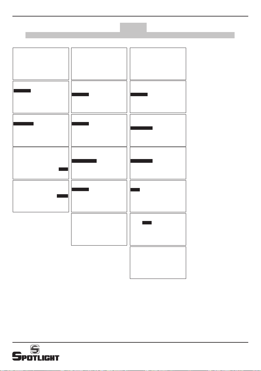
DISPLAY (Fig. 6-7-8-9)
Menu principale: MAIN
■SETUP
■MODE
■OPTIONS
■ADVANCED
Menu: SETUP (Fig. 6.1)
■DMX ADDRESS
■ETHERNET(nonimplementato)
DMX ADDRESS:
• +/ -per modificare l’indirizzo
• BACK per tornare al menù precedente senza salvare
le modifiche effettuate
• EXIT per uscire dal menu ritornando alla
visualizzazione principale senza salvare
• STORE per registrare in memoria l’indirizzo
modificato e tornare al menu precedente
Menu: MODE (Fig. 6.2-6.3)
■DMX
■STAND ALONE
DMX(Fig.6.2):
• SELECT per confermare la selezione effettuata
• BACK per tornare al menù precedente
• EXIT per tornare alla visualizzazione principale
DMX ADD CCT
1 Dimmer
2
CCT
step K
0 ÷10 3000
10 ÷60 3000 ÷3200
60 ÷70 3200
70 ÷120 3200 ÷4000
120 ÷130 4000
130 ÷180 4000 ÷5600
180 ÷190 5600
190 ÷240 5600 ÷6500
240 ÷255 6500
3Strobe
4 Zoom (*)
5
6
7
8
9
10
11
(*) Non implementato
STANDALONE(Fig.6.3):
• ENTER per confermare la selezione effettuata
• SELECT per selezionare una variabile
• +/ -per modificare i valori
• STORE per registrare in memoria il valore modificato
e tornare al menu precedente
• BACK per tornare al menù precedente
• EXIT per tornare alla visualizzazione principale
FresneLED 250 TW
8
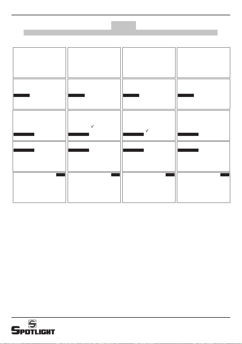
Menu: OPTIONS (Fig. 7 e 8)
■IRCONTROL(nonimplementato)
■SILENT MODE
■MASTER MODE
■SLAVE MODE
■AUTO CONFIGURE
SILENTMODE(Fig.7.1)
• ↑e↓per selezionare ENABLE o DISABLE
• SELECT per confermare
• appare il simbolo ✓se la funzione è attiva
• BACK per tornare al menù precedente
• EXIT per tornare alla visualizzazione principale
MASTERMODE(Fig.7.2):
Questa funzione è attivabile solo se il faro è in modalità
STAND ALONE.
In modalità DMX appare una scritta “MASTER DISABLE
BY
DMX” e non è possibile selezionare la funzione ENABLE.
• ↑e↓per selezionare ENABLE o DISABLE
• SELECT per confermare
• appare il simbolo ✓se la funzione è attiva
• BACK per tornare al menù precedente
• EXIT per tornare alla visualizzazione principale
Sul display sotto la scritta CCT appare la scritta
MASTER MODE.
SLAVEMODE(Fig.7.3):
Questa funzione è attivabile solo in se il faro è in modalità
STAND ALONE.
In modalità DMX appare una scritta “SLAVE DISABLE
BY
DMX” e non è possibile selezionare la funzione ENABLE.
• ↑e↓per selezionare ENABLE o DISABLE
• SELECT per confermare
Se si seleziona ENABLE viene richiesta la modalità di
controllo dello Zoom (*).
(*) Non essendo la funzione zoom implementata
potremo scegliere indifferentemente una delle due
modalità:
• ↑e↓per selezionare FREE ZOOM o ZOOM FROM
MASTER
• SELECT per confermare
• appare il simbolo ✓se la funzione è attiva
• BACK per tornare al menù precedente
• EXIT per tornare alla visualizzazione principale
Sul display sotto la scritta CCT appare la scritta SLAVE
MODE oppure SLAVE MODE, FREE ZOOM.
AUTOCONFIGURE(Fig.8)
Questa funzione copia le impostazioni da un faro sui
fari collegati in cascata.
Tutti i fari che si autoconfigurano si accendono e
rimangono accesi sino a che il tasto DONE non viene
premuto sul faro di partenza.
- AUTOCONFIGUREinmodalitàDMX(Fig8.1):
• ↑e↓per selezionare AUTO COPY, AUTO PATCH.
• ENTER per confermare (oppure BACK o EXIT
per tornare alla visualizzazione principale senza
apportare modifiche)
Modalità AUTO COPY, AUTO PATCH:
■AUTO COPY: stessi indirizzi DMX per tutti i fari
■AUTO PATCH: indirizzi DMX in progressione,
successivi all’ultimo indirizzo del faro
precedente
AUTO COPY
DMX ADDRESS
midi LED Dimmer CCT Strobe Zoom (*)
11234
21234
31234
41234
Configura i FresneLED 2-3-4 uguali al FresneLED 1
AUTO PATCH:
DMX ADDRESS
midi LED Dimmer CCT Strobe Zoom (*)
11234
2 5 6 7 8
3 9 10 11 12
4 13 14 15 16
Configura i FresneLED 2-3-4 uguali al FresneLED 1
con indirizzo DMX scalato
(*) Non implementato

FresneLED 250 TW
9
- AUTOCONFIGUREinmodalitàSTANDALONE
(Fig.8.2-8.3-8.4)
Vengono copiate le impostazioni (Modo, e
Opzioni) da un faro sui fari collegati in cascata
con le modalità indicate al capitolo descrittivo
precedente.
Verificare quindi sul faro di partenza l’impostazione
delle opzioni: Master, Slave, Silent Mode.
Se il faro di partenza è configurato come Master
(Fig.8.2):
• ↑e↓per selezionare FREE ZOOM o ZOOM FROM
MASTER (*).
(*) Non essendo la funzione zoom implementata
potremo scegliere indifferentemente una delle
due modalità.
• ENTER per confermare (oppure BACK o EXIT per
tornare alla visualizzazione principale senza
apportare modifiche).
Se il faro di partenza è configurato come Slave o nè
Master nè Slave (Fig.8.3-8.4):
• apparirà solo la voce MASTER OFF
• ENTER per confermare (oppure BACK o EXIT
per tornare alla visualizzazione principale senza
apportare modifiche)
Dopo aver premuto ENTER apparirà la scritta
AUTO PATCHING ... Attendere che tutti i
FresneLED siano autoconfigurati e premere il
pulsante DONE.
Menu: ADVANCED (Fig. 9)
■COLOR TEST
■FAN TEST
■FACTORY SETTING
Queste funzioni permettono di verificare il
funzionamento degli array di led e il funzionamento
della ventola.
La funzione Factory Setting è riservata al personale
abilitato dalla casa costruttrice.
• ↑e↓per selezionare la funzione
• ENTER per confermare
• BACK per tornare al menù precedente
• EXIT per uscire dal menu ritornando alla
visualizzazione principale.
FresneLED 250 TW
10
ELECTRICAL CONNECTIONS
Your luminaire has been designed for a supply voltage
from 100 to 240V, 50/60 Hz.
Before and during the installation, follow the
instructions below:
• Always check the earth wiring for the line being used.
• Ensure the voltage for the unit is the same as the one
used for the supply.
• The product is designed for indoor use (IP 20) :
consequently it has to be protected from dampness
and rain, if used in different conditions
• The luminaire CANNOT be connected to a dimmer.
The following lockable connectors are located on the
rear of the luminaire:
• for power supply:
- 1 Powercon BLUE (for power IN)
• for control:
- 1 x 5 pole XLR male connector for DMX 512 signal
input (DMX IN) or serial (Master/Slave)
- 1 x 5 pole XLR female connector for DMX 512 signal
transmission to the following luminaire (DMX THRU/
OUT) or serial (Master/Slave)
FOCUSING
By using the side handle ② it is possible to loosen the
luminaire and thus change its inclination. In the same
way, the luminaire can be rotated with respect to its
vertical axis by rotating on its hooking hinge.
MAINTENANCE
Service the luminaire at least once a year to check the
integrity of the electrical and mechanical parts and for
any possible software update.
On this purpose, only contact qualified dealers, to
guarantee correct and full servicing
RECYCLING
The product must be recycled or disposed of,
according to Directive 2002/96/CE
GENERAL DESCRIPTION
DESCRIPTION OF THE LUMINAIRE
Referring to drawings on page 2 (Picture 1)
① Suspension bracket
②Luminaire tilt adjustment handle
③ Accessories cover and locking spring
④Accessories guides
⑤ Zoom adjustment knob
⑥DMX THRU / OUT
⑦DMX IN
⑧Display
⑨ Display buttons
⑩Power supply IN (Powercon connector)
GENERAL INFORMATION
The luminaire you have bought satises directives
73/23/EEC as it complies with standards EN 60598-1
and EN 60598-2-17. The label located on the side of the
luminaire contains the following information:
• Model
• Supply voltage in V
• Power of the luminaire in W
• IP protection index
• Maximum allowed ambient temperature in °C
INSTALLATION
• The luminaire is intended for professional use only.
• Please note carefully the notes written on the labels
of the luminaire.
• The luminaire can be used both suspended and
mounted on a stand.
WARNING: The luminaire must always be
earthed

FresneLED 250 TW
11
FUNCTIONS DESCRIPTION
Display and Menu (see pictures 6-7-8-9)
All the fixture functions, control modes, options, etc are
performed by using the menu that appears on the rear
display of the luminaire and its 5 buttons.
CCT SETUP
CCT configuration allow the generation of a scale of
whites at different colour temperatures. The enabled
channels are:
- 1 grand master channel (Dimmer) controls the intensity
of the general output
- 1 channel sets the colour temperature levels
- 1 channel adjusts the strobe effect.
CONTROL MODE SETUP
DMX control mode
The DMX control mode allows to control the luminaire
by using a DMX lighting desk.
From the lighting desk it will then be possible to control
and change the following parameters:
• Master Intensity: This parameter, also called Dimmer,
proportionally adjusts the light output of the luminaire.
The light output will be adjusted between 0 and 255.
• Strobe: This parameter controls the flashing frequency
according to the Master intensity and the relevant
values for each colour. Values 0 and 255 do not make
the luminaire ash; values between 1 and 254 change
progressively the strobe frequency.
• CCT: This parameter allows to expand from 3000K to
6500K colour temperature in the white colour area.
RDM control mode
The RDM control protocol uses the DMX line to send/
receive information to/from the FresneLED regarding the
fixture set up, the DMX address, the led temperature, the
software version installed, etc.
The number of functions controlled by the RDM system
depends also on the RDM programme version installed
on the PC used to control the FresneLED or in the control
desk if the function is enabled.
STAND ALONE control mode
The Stand Alone mode allows the fixture to operate
in full autonomy without the use of any digital signal.
Moreover the choice of this mode inhibits the DMX
reception to give space to a possible Master/Slave
connection among more devices.
SILENT MODE
Thanks to the use of a real time feedback of the
temperature inside the Led, FresneLED can control in
a smart way the airflow through the ventilation. Silent
Mode is a function specically requested whereby a
greater attention to noise absence is necessary. By
activating this function the luminaire will continue
operating in “low noise” mode.

FresneLED 250 TW
12
ADVANCED FUNCTIONS
- Colour Test: This function allows to check the
functioning of the led array. The test lasts 5-6 seconds.
- Fan Test: This function allows to check the functioning
of the fan. The test lasts 5-6 seconds.
- Factory Setting: The access to this function is only for
personnel qualied by the manufacturer.
FIRMWARE UPDATE
By switching the luminaire on, the display will show for a
few seconds the number indicating the rmware version
installed.
Should the user wish to install an update in the luminaire
(ex. adding new functions) this can be done though a
suitable interface card (PCB 439 optional) connected on
one side to the DMX Input of the FresneLED and on the
other side to a UBS port of a PC where a programme
will be loaded to INSTALL the new rmware, that can be
supplied by e-mail.
CONNECTION OF MORE FIXTURES
Should more xtures be used together, they have to
be connected by using the sockets and the 5 poles
XLR plugs on the luminaires and they can have the
following combinations.
DMX CONNECTION
Besides the usual DMX connection with chain
connected luminaires, where the single addresses are
manually assigned, it is possible to set up a DMX auto-
configuration system with the following choices:
• Auto copy:
on the first luminaire of the chain select the
“autoconfig” function and choose from the menu the
“autocopy” configuration to set all the luminaires on
the same DMX address of the first fixture
• Auto patch:
on the first luminaire of the chain select the
“autoconfig” function and choose from the menu
the “auto patch” configuration to progressively get
the DMX free addresses after the one of the previous
luminaire.
CONNECTION OF MORE LUMINAIRES IN STAND
ALONE
The connection of the cables between the rst luminaire
and the following ones is the same as per the luminaires
in DMX.
In particular, by selecting the “autoconguration”
function all the luminaires after the first one will get the
same configuration of the first fixture.
If the user wishes all the fixtures following the first one
repeat exactly also the intensity and the values of the
various channels as the rst xture it will be necessary
to first select the “master” function on the first luminaire
and then select the “autoconfiguration” function.
In Master / Slave configuration the “silent mode”
function will have the option to enable all the luminaires
to adopt the same function or to disable it via a menu
with “silent disable”.
FresneLED 250 TW
13
Menu: MODE (pictures 6.2-6.3)
■DMX
■STAND ALONE
DMX(picture6.2):
• SELECT to select a variable
• BACK to go back to the previous menu
• EXIT to go back to the main menu
(*) Not implemented
STANDALONE(pictures6.3):
• ENTER to confirm the choice
• SELECT to select a variable
• + / - to change values
• STORE to memorize the changed value and exit the
menu
• BACK to go back to the previous menu
• EXIT to go back to the main menu
LUMINAIRE MANAGEMENT
FUNCTIONS SET UP (pictures 6-7-8-9)
The FresneLED foresees the use of the ve buttons ⑨
and of the display ⑧ to select the available functions.
Use:
• SET for a quick recall for the contextual menu
• MENU to recall the function menu
• ↑and ↓ to surf in the selected menu (highlighted
in bold)
• +/ -to change the values
• EXIT to exit the menu and go back to main menu
• BACK to go back to the previous menu
• ENTER to confirm selection
• SELECT to select a menu variable or to pass from the
variable to the value of the variable itself
• STORE to memorize the modified value
• DONE to end a procedure (changes will be saved)
DISPLAY (pictures 6-7-8-9)
Main menu: MAIN
■SETUP
■MODE
■OPTIONS
■ADVANCED
Menu: SETUP (picture 6.1)
■DMX ADDRESS
■ETHERNET(notimplemented)
DMX ADDRESS:
• +/ -to change the address
• BACK to go back to the previous menu without
saving the changes
• EXIT to exit the menu and go back to the main
screen without saving
• STORE to memorize the changed address and exit
the menu
DMX ADD CCT
1 Dimmer
2
CCT
step K
0 ÷10 3000
10 ÷60 3000 ÷3200
60 ÷70 3200
70 ÷120 3200 ÷4000
120 ÷130 4000
130 ÷180 4000 ÷5600
180 ÷190 5600
190 ÷240 5600 ÷6500
240 ÷255 6500
3Strobe
4 Zoom (*)
5
6
7
8
9
10
11

FresneLED 250 TW
14
Menu: OPTIONS (pictures 7 e 8)
■IRCONTROL(notimplemented)
■SILENT MODE
■MASTER MODE
■SLAVE MODE
■AUTO CONFIGURE
SILENTMODE(picture7.1)
• ↑and ↓to select ENABLE or DISABLE
• SELECT to confirm
• the symbol ✓appears if the function is active
• BACK to go back to the previous menu
• EXIT to go back to the main menu
MASTERMODE(picture7.2):
This function can be activated only if the luminaire is
in the STAND ALONE mode.
In DMX mode “MASTER DISABLE BY DMX” will appear
and it is not possible to select the ENABLE function.
• ↑and ↓to select ENABLE or DISABLE
• SELECT to confirm
• the symbol ✓appears if the function is active
• BACK to go back to the previous menu
• EXIT to go back to the main menu
On the display MASTER MODE appears under CCT.
SLAVEMODE(picture7.3):
This function can be activated only if the luminaire is
in the STAND ALONE mode.
In DMX mode “SLAVE DISABLE BY DMX” will appear
and it is not possible to select the ENABLE function.
• ↑and ↓to select ENABLE or DISABLE
• SELECT to confirm
By selecting ENABLE the zoom control mode will be
required (*).
(*) Since the zoom function is not implemented it will
be possible to choose indifferently one of the two
modes
• ↑and ↓to select FREE ZOOM or ZOOM FROM
MASTER
• SELECT to confirm
• the symbol ✓appears if the function is active
• BACK to go back to the previous menu
• EXIT to go back to the main menu
On the display SLAVE MODE or SLAVE MODE, FREE
ZOOM appears under CCT.
AUTOCONFIGURE(picture8)
This function copies the set up from a luminaire to the
chain connected ones.
All the auto-configurating luminaries switch on and
remain lit until the DONE button is pressed on the
starting luminaire.
- AUTO CONFIGURE in DMX MODE(picture8.1):
• ↑and ↓to select AUTO COPY, AUTO PATCH
( The ZOOM OFFSET function is not implemented)
• ENTER to conrm (or BACK or EXIT to go back to the
main menu without making any changes)
AUTO COPY, AUTO PATCH or ZOOM OFFSET Mode:
■AUTO COPY: same DMX addresses for all the
luminaires
■AUTO PATCH: progressive DMX addresses, following
the address of the previous luminaire
AUTO COPY
DMX ADDRESS
FresneLED Dimmer CCT Strobe Zoom (*)
11234
21234
31234
41234
It congures the FresneLED 2-3-4 like the
FresneLED 1
AUTO PATCH:
DMX ADDRESS
FresneLED Dimmer CCT Strobe Zoom (*)
11234
25678
3 9 10 11 12
4 13 14 15 16
It congures the FresneLED 2-3-4 like the
FresneLED 1 with a shifted DMX address
(*) Not implemented

FresneLED 250 TW
15
- AUTO CONFIGURE in STAND ALONE MODE
(pictures8.2-8.3-8.4)
The set up of one luminaire (Mode and Options) is
copied on all the other chain connected luminaires
with the modes described in the previous chapter.
Check the options setup on the starting luminaire:
Master, Slave, Silent Mode.
If the starting luminaire is set up as Master
(Picture 8.2)
• ↑and ↓to select FREE ZOOM or ZOOM FROM
MASTER (*)
(*) Since the zoom function is not implemented it
will be possible to choose indifferently one of the
two modes
• ENTER to conrm (or BACK or EXIT to go back to
the main screen without making any changes)
If the starting luminaire is configured as Slave or
neither Master nor Slave (pictures 8.3-8.4):
• Only MASTER OFF will appear
• ENTER to conrm (or BACK or EXIT to go back to
the main menu without making any changes)
After having kept the ENTER button pressed AUTO
PATCHING will appear .... Wait until all the FresneLED
are auto-configured then press DONE
Menu: ADVANCED (picture 9.4)
■COLOR TEST
■FAN TEST
■FACTORY SETTING
• ↑and ↓to select the function
• ENTER to confirm
• BACK to go back to the previous menu
• EXIT to exit the menu and go back to the main menu.
FresneLED 250 TW
ADDRESS: SET
CCT 3Ch
002
DMX ADDRESS: EXIT
BACK
STORE
-
003
MAIN
MODE
OPTIONS
ADVANCED
SETUP
ETHERNET
ID: 00221
ADDRESS: SET
MENU
CCT 3Ch
002
ADDRESS: SET
MENU
CCT 3Ch
002
NEW DMX ADDRESS SET DMX MODE
EXIT
BACK
ENTER
EXIT
BACK
ENTER
DMX ADDRESS
MODE
STAND ALONE
NOW: CCT 3Ch
EXIT
BACK
ENTER
DMX
MODE
STAND ALONE
NOW: CCT 3Ch
EXIT
BACK
ENTER
DMX
SETUP
MAIN
OPTIONS
EXIT
BACK
ENTER
SETUP
DMX ADDRESS: EXIT
BACK
STORE
+
-
003
MENU
+
MODE
DMX MODE EXIT
BACK
SELECT
CCT 3Ch
ADDRESS: SET
MENU
CCT 3Ch
002
SET STAND ALONE MODE
MODE
NOW: CCT 3Ch
EXIT
BACK
ENTER
DMX
MAIN
OPTIONS
EXIT
BACK
ENTER
SETUP
MODE
STAND ALONE EXIT
BACK
ENTER
CCT
STEADY MANUAL MODE SET
MENU
CCT
STAND ALONE
CCT
STROBE:
BACK
STORE
SELECT
DIMM:
CCT:
000
255
000
RGBW + CCT
STROBE:
BACK
STORE
SELECT
+
-
DIMM:
CCT:
000
255
000
↑
↓
ADVANCED
↑
↓
ADVANCED
↑
↓
↑
↓
↑ ↑
↓↓
↑
↓
↑
↓
↑
↓
↑
↓
16
6.1 6.2 6.3
Fig. 6

FresneLED 250 TW
STEADY MANUAL MODE SET
MENU
CCT
SILENT MODE
MAIN
ADVANCED
EXIT
BACK
ENTER
↑
↓
SETUP
MODE
OPTIONS
MASTER MODE
SLAVE MODE
AUTO CONFIGURE
EXIT
BACK
ENTER
↑
↓
IR CONTROL
SILENT MODE
OPTIONS
MASTER MODE
SLAVE MODE
AUTO CONFIGURE
EXIT
BACK
ENTER
↑
↓
IR CONTROL
SILENT MODE
SILENT FAN MODE EXIT
BACK
SELECT
↑
↓
ENABLE
DISABLE
STEADY MANUAL MODE SET
MENU
CCT
OPTIONS
STEADY MANUAL MODE SET
MENU
CCT
MASTER MODE
MAIN
ADVANCED
EXIT
BACK
ENTER
↑
↓
SETUP
MODE
OPTIONS
SLAVE MODE
AUTO CONFIGURE
EXIT
BACK
ENTER
↑
↓
IR CONTROL
SILENT MODE
OPTIONS
SLAVE MODE
AUTO CONFIGURE
EXIT
BACK
ENTER
↑
↓
IR CONTROL
SILENT MODE
MASTER MODE EXIT
BACK
SELECT
↑
↓
ENABLE
DISABLE
STEADY MANUAL MODE SET
MENU
CCT
MASTER MODE
OPTIONS
MASTER MODE
MASTER MODE
STEADY MANUAL MODE SET
MENU
CCT
SLAVE MODE
MAIN
ADVANCED
EXIT
BACK
ENTER
↑
↓
SETUP
MODE
OPTIONS
AUTO CONFIGURE
EXIT
BACK
ENTER
↑
↓
IR CONTROL
SILENT MODE
OPTIONS
AUTO CONFIGURE
EXIT
BACK
ENTER
↑
↓
IR CONTROL
SILENT MODE
SLAVE MODE EXIT
BACK
SELECT
↑
↓
ENABLE
DISABLE
SLAVE ZOOM MODE EXIT
BACK
SELECT
↑
↓
FREE ZOOM
ZOOM FROM MASTER
STEADY MANUAL MODE SET
MENU
CCT
SLAVE MODE, FREE ZOOM
OPTIONS
MASTER MODE
MASTER MODE
SLAVE MODE
SLAVE MODE
17
Fig. 7
7.1 7.2 7.3
FresneLED 250 TW
STEADY MANUAL MODE SET
MENU
CCT
MASTER MODE
DONE
AUTO PATCHING ...
DONE
AUTO PATCHING ...
ADDRESS: SET
CCT 3Ch
002
AUTO CONFIGURE FROM DMX MODE AUTO CONFIGURE FROM STAND ALONE
(MASTER ENABLE)
MENU
MAIN
ADVANCED
EXIT
BACK
ENTER
Β
?
SETUP
MODE
OPTIONS
OPTIONS
MASTER MODE
SLAVE MODE
EXIT
BACK
ENTER
Β
?
IR CONTROL
SILENT MODE
AUTO CONFIGURE
MAIN
ADVANCED
EXIT
BACK
ENTER
Β
?
SETUP
MODE
OPTIONS
OPTIONS
MASTER MODE
SLAVE MODE
EXIT
BACK
ENTER
Β
?
IR CONTROL
SILENT MODE
AUTO CONFIGURE
AUTO CONFIG DMX EXIT
BACK
ENTER
Β
?
AUTO COPY
AUTO PATCH
AUTO CONFIG STAND AL EXIT
BACK
ENTER
Β
?
FREE ZOOM
ZOOM FROM MASTER
STEADY MANUAL MODE SET
MENU
CCT
SLAVE MODE
DONE
AUTO PATCHING ...
AUTO CONFIGURE FROM STAND ALONE
(SLAVE ENABLE)
MAIN
ADVANCED
EXIT
BACK
ENTER
Β
?
SETUP
MODE
OPTIONS
OPTIONS
MASTER MODE
SLAVE MODE
EXIT
BACK
ENTER
Β
?
IR CONTROL
SILENT MODE
AUTO CONFIGURE
AUTO CONFIG STAND AL EXIT
BACK
ENTER
MASTER OFF
STEADY MANUAL MODE SET
MENU
CCT
DONE
AUTO PATCHING ...
AUTO CONFIGURE FROM STAND ALONE
(NO MASTER NO SLAVE ENABLE)
MAIN
ADVANCED
EXIT
BACK
ENTER
Β
?
SETUP
MODE
OPTIONS
OPTIONS
MASTER MODE
SLAVE MODE
EXIT
BACK
ENTER
Β
?
IR CONTROL
SILENT MODE
AUTO CONFIGURE
AUTO CONFIG STAND AL EXIT
BACK
ENTER
MASTER OFF
18
8.1 8.2 8.3 8.4
Fig. 8

FresneLED 250 TW
ADDRESS: SET
RGBW 7Ch
002
MAIN
MODE
OPTIONS
ADVANCED
FAN TEST
FACTORY SETTINGS
ADVANCED
EXIT
BACK
ENTER
↑
↓
EXIT
BACK
ENTER
↑
↓
COLOR TEST
SETUP
MENU
SCENE
ADVANCED
19
Fig. 9
9.1

Spotlight s.r.l.
Via Sardegna 3
20098 S. Giuliano Milanese
Milano - Italy
Tel. +39.02.98830.1
Fax +39.02.98830.22
E-mai: [email protected]
www.spotlight.it
certified quality management system ISO 9001 :
2008
FresneLED 250 TW
This manual suits for next models
1
Table of contents
Languages:
Other Spotlight Floodlight manuals


