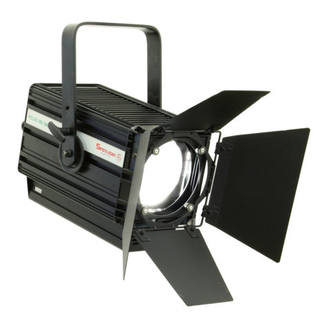
Spotlight ProfiLED 200 UD User manual

Manuale utente - User manual
cod. PRLED200ZSCWUD • PRLED200ZSNWUD • PRLED200ZSWWUD
PRLED200ZWCWUD• PRLED200ZWNWUD • PRLED200ZWWWUD
ProLED 200 UD

ProfiLED 200 UD
456
332 792
456
332 642
2
5
1
6
7
2
3
8
4
14
13
12
10
9
11 15
Fig. 1
Kg. 13,5 Kg. 13
ATTENZIONE: Prima di usare questi apparecchi,
leggere attentamente le istruzioni che seguono.
Spotlight srl non potrà essere ritenuta responsabile di
danni derivanti dalla non osservanza di dette istruzioni.
SAFETY WARNING: Before using this product,
read the present instructions carefully.
Spotlight srl will not be responsible for damage
resulting from instructions not being followed.
Dimensioni (mm) e peso - Dimensions (mm) and weight
ProfiLED 200 ZS UD ProfiLED 200 ZW UD

ProfiLED 200 UD
DISP
DIMM
(dimmer setting)
EFF
(effect)
CUR
(curve)
HENO
(discharge lamp
emulation with DMX)
ON
(display always on)
OFF
(display always off)
FRE
320 - 1200Hz
FAN
ON
SILE
(silent mode)
CAL
(calibration
DMX signal)
CHAN
(setup channels
used)
3 CH
2 CH
1 CH
SURE
REM
(set remote ID) 0 - 250
UDIM
ON
MAX
(set the max value
of brightness)
LIN
(linear curve)
QUAD
(quadratic curve)
DFSE
(load default)
OFF
HALO
(halogen lamp
emulation with DMX)
MIN
(set the min value
of brightness)
3
11
Fig. 2
Pulsanti display - Display buttons

ProfiLED 200 UD
CONNESSIONI ELETTRICHE
Il vostro faro è stato progettato per una tensione di
alimentazione da 100 a 240V, 50/60 Hz.
Prima e durante l’installazione osservare le seguenti norme:
• Vericare sempre l’efcienza del collegamento a terra
della linea in uso.
• Vericare che la tensione di alimentazione corrisponda
a quella dell’apparecchio
• L’apparecchio è previsto per uso all’interno (IP 20):
pertanto deve essere protetto dall’umidità e dalla
pioggia se usato in condizioni diverse.
Sulla parte posteriore del faro sono collocati i
seguenti connettori:
•di alimentazione (con blocco di sicurezza
antisgancio):
- 1 connettore Powercon BLU, per ingresso (POWER IN)
- 1 connettore Powercon BIANCO, per uscita (POWER
OUT)
•dicontrollo:
- 1 connettore a 5 poli XLR maschio per l’ingresso del
segnale DMX 512 (DMX IN) o seriale (Master/Slave)
- 1 connettore a 5 poli XLR femmina per la trasmissione
del segnale DMX 512 al faro successivo (DMX THRU/
OUT) o seriale (Master/Slave)
PUNTAMENTO
Tramite la maniglia laterale ②si può allentare il
bloccaggio del faro in una certa posizione e modicare
la sua inclinazione. Per la rotazione sull’asse verticale,
far ruotare il faro sul perno di aggancio. Con le
maniglie a leva ④si effettua la regolazione dello
zoom, allargando o stringendo il fascio di luce, e la
regolazione della messa a fuoco. Tramite le quattro
lamelle sagomatrici ③si può sagomare il fascio di luce
per ottenere forme speciali.
MANUTENZIONE
Non aprire l’apparecchio. La manutenzione deve essere
eseguita esclusivamente dal costruttore o dal suo servizio
di assistenza. Sottoporre il faro a revisione almeno una
volta all’anno per controllare l’integrità delle parti
elettriche e meccaniche e l’aggiornamento del software.
Utilizzare i pomelli ⑦per accedere al vano lenti per la
loro pulizia.
RICICLAGGIO
Il prodotto deve essere riciclato o smaltito
secondo la direttiva 2002/96/CE
DESCRIZIONE DEL PROIETTORE
Riferendosi ai disegni di pag. 2:
① Staffa di sospensione
② Maniglia per regolazione inclinazione faro
③Leve comando lamelle sagomatrici
④ Maniglie a leva di regolazione zoom e messa a fuoco
⑤ Guide porta accessori
⑥ Tettuccio accessori con molla di bloccaggio
⑦ Pomelli scorrimento e ssaggio tettucci
⑧ Sportello di accesso a vano portagobos e lenti
⑨ Connettore DMX THRU
⑩ Connettore DMX IN
⑪ Display con pulsanti menu
⑫ Alimentazione IN (connettore Powercon)
⑬ Alimentazione OUT (connettore Powercon)
⑭ Manopola di regolazione intensità luminosa
(in modalità Potenziometro Locale)
⑮ Anello per aggancio fune di sicurezza
INDICAZIONI GENERALI
Il proiettore in Vs possesso risponde alle Direttive Europee
2006/95/CE, 2004/108/CE e 2011/65/UE.
La targhetta che è sistemata sul anco del proiettore,
contiene le seguenti informazioni:
•Modello
• Tensione di alimentazione in V
• Potenza in W
• Indice di protezione IP
• Massima temperatura ambiente ammissibile in °C
INSTALLAZIONE
• Il proiettore è progettato esclusivamente per impiego
professionale.
• Non puntare il faro direttamente negli occhi
• Si prega di prestare la dovuta attenzione alle note
riportate sull’etichetta dell’apparecchio.
• Ricordarsi di collegare la fune di sicurezza se previsto
dalle norme di sicurezza locali.
• ll proiettore può essere usato sia sospeso sia montato su
cavalletto.
Per l’utilizzo di gobo: far scorrere in avanti lo sportello
del’apposito vano ⑧, inserire il portagobo e riportare il
coperchio in posizione arretrata per bloccare il portagobo
e impedire al contempo fughe di luce.
Tipo di gobo previsto: misura “B”
4
ATTENZIONE: L'APPARECCHIO DEVE
ESSERE COLLEGATO A TERRA
ATTENZIONE: L'APPARECCHIO PUO' ESSERE
COLLEGATO A UN DIMMER

ProfiLED 200 UD
MODALITA' DI FUNZIONAMENTO
• L’apparecchio rileva automaticamente la tensione di funzionamento in un range compreso fra 100÷240V.
• Il faro è predisposto per poter essere collegato ad un dimmer e contemporaneamente essere regolato tramite il
potenziometro locale o attraverso una console DMX
• Priorità di controllo: l’apparecchio risponde alle diverse posibilità di controllo con logica LTP (Latest Takes Precedence)
IMPOSTAZIONE CANALI:
• 3 CH 1 - Master Dimmer (Coarse)
2 - Master Dimmer (Fine)
3 - Strobo Effect (vedi tabella a lato)
• 2 CH 1 - Master Dimmer (Coarse)
2 - Strobo Effect (vedi tabella a lato)
• 1 CH 1 - Master Dimmer (Coarse)
1)ModalitàPOTENZIOMETROLOCALE.In questa modalità è possibile regolare l’intensità luminosa dell’apparecchio da
0 a 100% agendo sulla manopola del potenziometro ⑭posta sul retro del faro.
2) Modalità DMX. Per il controllo in questa modalità è necessario il collegamento tramite cavo DMX da un dispositivo
di controllo (es. console) al connettore del faro DMX IN. E’ possibile assegnare un indirizzo DMX compreso fra 001
e 512, agendo sui pulsanti UP (+) e DOWN (-) e confermando inne la scelta con il pulsante ENTER/MODE. Più fari
possono essere connessi in cascata, collegando l’uscita DMX THRU di un faro all’ingresso DMX IN del faro successivo.
MENU IMPOSTAZIONI (vedi Fig. 2)
A display spento, premere un tasto qualsiasi per attivarne la visualizzazione.
Premere il pulsante MENU per accedere alle impostazioni del faro.
Con i tasti UP (+) oppure DOWN (-) è possibile scorrere le voci di menu e modicare i valori dei settaggi.
Premere ENTER/MODE per confermare e passare all’opzione successiva.
• DIMM: selezione curva ed effetto di regolazione
• UDIM: abilita / disabilita il controllo via dimmer dell’intensità luminosa
• DISP: attiva / disattiva Display
• FRE: regolazione frequenza del PWM
• FAN: regolazione silenziosità / velocità ventola
• CAL: impostazione limiti valore Min / Max intensità luminosa
• DFSE: reset a settaggio di fabbrica
• CHAN: impostazione del numero di canali da utilizzare
• REM: Non implementato
5
CANALE3(EffectChannel)-TABELLADMX
DMX-effetto DMX-intervallovalori
Dimmer 0 - 9
Effetto Sync Strobo (da 0,5 a 30Hz) 10 - 57
Dimmer 58 - 59
Effetto Pulsato in spegnimento (da lento a veloce) 60 - 108
Dimmer 109 - 110
Effetto Pulsato in accensione (da veloce a lento) 111 - 159
Dimmer 160 - 161
Random Strobo (da lento a veloce) 162 - 207
Dimmer 208 - 209
Random Strobo (da lento a veloce) 210 - 255

ProfiLED 200 UD
6
DESCRIPTION OF THE LUMINAIRE
Referring to gures on pages 2-3:
① Suspension yoke
② Luminaire tilt adjustment handle
③Levers for framing shutters adjustment
④ Lever handles for lens adjustment: focus and zoom
⑤ Accessories guides
⑥ Accessories cover and locking spring
⑦ Sliding cover xing knobs
⑧ Lens and gobo slot sliding cover
⑨ DMX THRU connector
⑩ DMX IN connector
⑪ Power supply IN (Powercon connector)
⑫ Power supply OUT (Powercon connector)
⑬ Display with buttons menu
⑭ Light intensity adjustment knob
(in Local Potentiometer mode)
⑮ Ring for safety rope hooking
INTRODUCTION
The luminaire you have bought complies to 2006/95/EC,
2004/108/EC and 2011/65/EU European Directives.
The label on the side of the luminaire lists the following
information:
• Model
• Mains supply voltage (V)
• Lamp wattage (W)
• Protection index (IP)
• maximum allowed ambient temperature in °C
INSTALLATION
• The luminaire is intended for professional use only.
• Do not direct the light beam straight into somebody’s
eyes
• Please note carefully the notes written on the labels
of the luminaire.
• The luminaire can be used both suspended and
mounted on a stand.
For gobo use: slide forward the slot cover ⑧, insert the
gobo holder and slide backward the cover to lock the
gobo holder in position and avoid light spill.
Foreseen gobo types: “B” size.
ELECTRICAL CONNECTIONS
Your luminaire has been designed for a supply voltage
from 100 to 240V, 50/60 Hz.
Before and during the installation, follow the
instructions below:
• Always check the earth wiring for the line being used.
• Ensure the voltage for the unit is the same as the one
used for the supply.
• The product is designed for indoor use (IP 20) :
consequently it has to be protected from dampness
and rain, if used in different conditions
Thefollowinglockableconnectorsarelocatedonthe
rearoftheluminaire:
• for power supply:
- 1 Powercon BLUE (for power IN)
- 1 Powercon WHITE (for power OUT)
• for control:
- 1 x 5 pole XLR male connector for DMX 512 signal
input (DMX IN) or serial (Master/Slave)
- 1 x 5 pole XLR female connector for DMX 512 signal
transmission to the following luminaire (DMX THRU/
OUT) or serial (Master/Slave)
FOCUSING
Using the handle on the side ②it is possible to loosen
the luminaire when it is locked in a certain position and
thus change its inclination. You can rotate the luminaire
on the vertical axis by rotating it on its hook clamp. The
zoom is adjusted with lever handles ④ by widening or
narrowing the light beam and focusing.
Through the four framing shutters ③it is possible to
prole the light beam to obtain special shapes.
Use knobs ⑦ to access the lenses for cleaning.
MAINTENANCE
Do not open the xture. Maintenance should be performed
only by the manufacturer or by its service agent.
The luminaire must be serviced at least once a year, to
check the integrity of its electrical and mechanical parts
and to keep software updated.
RECYCLING
The product must be recycled or disposed of,
according to Directive 2002/96/CE.
WARNING: THE LUMINAIRE MUST ALWAYS
BE EARTHED
WARNING: THIS UNIT CAN BE
CONNECTED TO A DIMMER

ProfiLED 200 UD
7
FUNCTIONING MODE
• The xture automatically detects the functioning tension in a range between 100÷240V.
• The luminaire can be connected to a dimmer and, at the same time, it can be set through the local potentiometer or
through a DMX console
• Control priority: the xture works according to LTP mode (Latest Takes Precedence)
SETUP CANALI:
• 3 CH 1 - Master Dimmer (Coarse)
2 - Master Dimmer (Fine)
3 - Strobo Effect (see side table)
• 2 CH 1 - Master Dimmer (Coarse)
2 - Strobo Effect (see side table)
• 1 CH 1 - Master Dimmer (Coarse)
1)LOCALPOTENTIOMETERMode:In this mode it is possible to adjust the light output of the xture from 0 to 100%
by using the potentiometer knob ⑭ on the rear of the luminaire.
2) DMX Mode: To control this mode it is necessary the connection through DMX cable from a control device (ex.
console) to the luminaire DMX IN connector. It is possible to assign any DMX address from 001 and 512, by using the
buttons UP (+) and DOWN (-) and then conrming the choice with the button ENTER/MODE. More luminaires can be
chain connected, connecting the DMX THRU of a luminaire to the DMX IN of the following xture.
SET-UP MENU (see Fig. 2)
When the display is off, push any button to activate the visualisation.
Push the MENU button to access the luminaire set-up.
With the buttons UP (+) or DOWN (-) it is possible to change the set-up values.
Press ENTER/MODE to conrm and pass to the following option.
• DIMM: curve selection and set up effect
• UDIM: enables / disables the light intensity/output through the dimmer
• DISP: activate / deactivate Display
• FRE: PWM frequence set up
• FAN: fan silence / speed set up
• CAL: Min / Max value limits set up of light intensity
• DFSE: reset to manufacturer set up
• CHAN: setup channels to be used
• REM: Not implemented
CHANNEL 3 (Effect Channel) - DMX TABLE
DMX-effect DMX-range
Dimmer 0 - 9
Sync Strobo Effect (from 0,5 to 30Hz) 10 - 57
Dimmer 58 - 59
Pulse Effect from ON to OFF (slow to fast) 60 - 108
Dimmer 109 - 110
Pulse Effect from OFF to ON (fast to slow) 111 - 159
Dimmer 160 - 161
Random Strobo (slow to fast) 162 - 207
Dimmer 208 - 209
Random Strobo (slow to fast) 210 - 255

Spotlight s.r.l.
Via Sardegna 3
20098 S. Giuliano Milanese
Milano - Italy
Tel. +39.02.98830.1
Fax +39.02.98830.22
E-mail: [email protected]
www.spotlight.it
ProfiLED 200 UD
This manual suits for next models
6
Table of contents
Languages:
Other Spotlight Floodlight manuals

