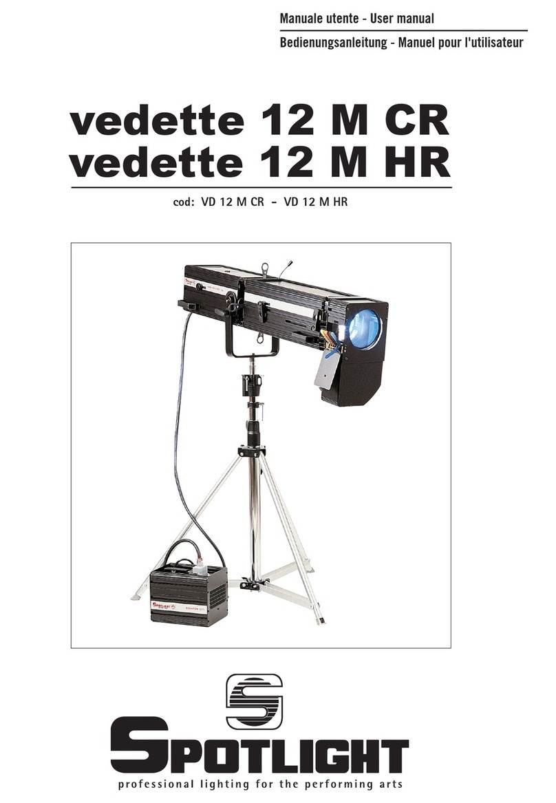
Spotlight vedette 12 M MT User manual

Manuale utente - User manual
cod: VD 12 M MT
vedette 12 M MT

Vedette 12 M MT
ATTENZIONE: Prima di usare questi
apparecchi, leggere attentamente le istruzioni
che seguono. Spotlight srl non potrà essere
ritenuta responsabile di danni derivanti dalla non
osservanza di dette istruzioni.
SAFETY WARNING: Before using this
product, read the present instructions carefully.
Spotlight srl will not be responsible for damage
resulting from instructions not being followed.
2
1
12
4
14
5
7
68
9
13
11
2
1
10 3

Vedette 12 M MT
DESCRIZIONE DEL FARO
Riferendoci alle immagini
①Corpo lanterna
②Bacinella portalampada
③Pomello di apertura bacinella
④Staffa per montaggio su cavalletto
⑤Manopole per regolazione lenti
⑥Manopole per regolazione ghigliottine
⑦Manopola per rotazione set ghigliottine
⑧Leva per controllo diaframma
⑨Leva per controllo dimmer
⑩Vite per regolazione centraggio lampada
⑪Pomolo regolazione messa a fuoco
⑫Cavo di collegamento al ballast
⑬Ballast
⑭Cambiacolori (opzionale)
GENERALITÀ
Faro seguipersona per lampade a ioduri metallici tipo
bispina (Single Ended).
Alimentazione a 220 V-50 Hz tramite apposito ballast.
Possibilità di montaggio anteriore di cambiacolori.
Il proiettore in Vs possesso risponde alle Direttive
Europee 2006/95/CE, 2004/108/CE e 2011/65/UE.
La targhetta che è localizzata sulla fiancata del faro,
contiene le seguenti informazioni:
• modello
• massima tensione di alimentazione in V
• massima potenza della lampada in W
• indice di protezione IP
• massima temperatura ambiente ammissibile in °C
• massima temperatura del corpo del faro in °C
• distanza minima da ogni superficie infiammabile
• informazioni per riconoscere la posizione 0° del
faro: quando la punta della freccia è rivolta verso
l’alto
• angolo massimo di inclinazione verso l’alto e verso
il basso. Questi limiti, imposti dal costruttore
della lampada, non devono essere superati pena
una riduzione della vita utile della lampada o il
deterioramento del faro.
INSTALLAZIONE
II faro viene normalmente usato montato su un
cavalletto.
Estrarre il faro dall’imballaggio e montarlo su di un
cavalletto, quindi montare il cambiacolori se previsto.
ATTENZIONE!
NON INSTALLARE IL FARO SU SUPERFICI
NORMALMENTE INFIAMMABILI E MANTENERE LA
DISTANZA MINIMA INDICATA SULLA TARGHETTA.
INSTALLAZIONE E CAMBIO DELLA LAMPADA
ATTENZIONE!
- SCOLLEGARE SEMPRE IL FARO PRIMA DI APRIRLO O
SMONTARLO.
- PRIMA DI APRIRE E/O RICHIUDERE LA BACINELLA
PORTALAMPADA RUOTARE IN SENSO ORARIO E
COMPLETAMENTE IL POMELLO ⑪ IN MODO DA
ARRETRARE IL PORTALAMPADA ED EVITARE DI
DANNEGGIARE LA LAMPADA STESSA!
Aprire la bacinella ②tramite il pomello ③per accedere
allo zoccolo portalampada. Montare la lampada prevista,
tenendo presente che questa può essere danneggiata
dal contatto con la pelle o con altri elementi unti e/o
sporchi di grasso. Richiudere la bacinella portalampada e
riportare la calotta e la lampada in posizione, utilizzando
il pomello ⑪.
Collegare il faro (tramite il cavo già montato) all’i-
doneo alimentatore e collegare quest’ultimo alla rete
di alimentazione rispettando le normative di sicurezza
vigenti.
Ricordarsi che questi fari funzionano con lampade a
ioduri metallici che emettono raggi UV e che possono
scoppiare a caldo. Attendere quindi che la lampada sia
fredda prima di sostituirla.
Utilizzare solo lampade del modello e della potenza
descritta (vedere tabella lampade).
Tenere sotto controllo il tempo di effettivo
funzionamento di ciascuna lampada. Occorre, infatti,
sostituire la lampada, anche se funzionante, quando ha
raggiunto la vita massima prevista dal costruttore.
IL FUNZIONAMENTO OLTRE LA VITA NOMINALE
AUMENTA MOLTO I RISCHI DI ESPLOSIONE DELLA
LAMPADA STESSA.
3

Vedette 12 M MT
chiusura totale).
Con le manopole ⑥si può effettuare il taglio di parte
dello spot luminoso, mentre utilizzando il pomello ⑦
si può ottenere la rotazione di tutto il sistema porta-
ghigliottine.
Tramite la leva ⑨è possibile attenuare l’intensità del
fascio luminoso.
Nel caso sia presente anche il cambiacolori, si può
inserire il disco porta-gelatina del colore prescelto
agendo sulla levetta del rispettivo colore.
Tenere presente che l’inserimento di un ulteriore disco
sblocca il disco precedentemente inserito.
PRIMA Dl RICHIUDERE IL CAMBIACOLORI ACCERTARSI
CHE IL FARO SIA SPENTO.
MANUTENZIONE
Per una maggiore resa ottica si consiglia una periodica
pulizia dalla lente e della calotta a specchio.
Ricordarsi sempre di scollegare il faro
dall’alimentazione elettrica e di lasciar raffreddare la
lampada prima di effettuare qualsiasi intervento di
pulizia o manutenzione.
Per ragioni di sicurezza verificare (almeno una volta
all’anno) il buon isolamento di tutte le parti elettriche e
l’integrità delle parti meccaniche.
ATTENZIONE!
SPEGNERE SUBITO IL FARO NEL CASO VI FOSSE UNA
LENTE ROTTA O MANCANTE.
RICICLAGGIO
Il prodotto deve essere riciclato o smaltito
secondo la direttiva 2002/96/CE
4
CENTRATURA DELLA LAMPADA
Effettuare la regolazione a lampada calda, cioé almeno
4/5 minuti dopo l’accensione.
E’ possibile centrare la lampada agendo sulla vite di
regolazione ⑩. La regolazione va effettuata controllando
l’uniformità dello spot luminoso e regolando nel
contempo la posizione della lampada nello specchio.
MESSA IN SERVIZIO
Accertarsi sempre che la tensione di rete corrisponda
a quella indicata dalla targhetta fissata sul faro o sul
rispettivo ballast prima di accendere l’apparecchio, e
di aver rispettato il codice colore se avete montato
o sostituito la spina di alimentazione (blu = neutro -
giallo/verde = messa a terra) .
Nel caso sia presente anche il cambiacolori, accertarsi
che questo sia stato aperto.
Per accendere il faro, inserire l’interruttore generale
magnetotermico di sicurezza sull’alimentatore e premere
l’apposito pulsante d’innesco per una durata massima di
circa 2 secondi.
IN CASO Dl MANCATA ACCENSIONE, NON INSISTERE,
MA SPEGNERE L’INTERRUTTORE GENERALE E RIPETERE
TUTTA LA PROCEDURA DOPO CIRCA 10 SECONDI.
ATTENZIONE !
DURANTE LA FASE D’INNESCO DELLA LAMPADA, NEL
FARO È PRESENTE ALTA TENSIONE.
È normale e non pericoloso che l’accensione di un faro
nuovo causi una leggera uscita di fumo dalle feritoie
di aereazione; ciò è dovuto all’essicazione di probabili
residui di olio di lavorazione e/o verniciatura e non è
assolutamente pericoloso.
Si consiglia di effettuare la prima accensione con
una durata max. di 15 minuti al fine di permettere
l’essicazione delle vernici e di favorire la durata dei
componenti.
PUNTAMENTO
L’apertura o chiusura del fascio luminoso (zoom e messa
a fuoco) è ottenibile tramite lo spostamento coordinato
delle due manopole ⑤poste sulla fiancata destra del
faro che comandano lo spostamento dei carrelli porta-
lenti.
La larghezza dello spot luminoso è ulteriormente
controllabile tramite la leva ⑧che controlla l’apertura/
chiusura del diaframma (con possibilità anche di

Vedette 12 M MT
5
DESCRIPTION OF THE LUMINAIRE
Refer to pictures
①Luminaire body
②Lamp holder tray
③Knob to open tray
④Bracket for mounting on stand
⑤Levers for adjusting lenses
⑥Levers for shutters adjusting
⑦Knob for shutter-set rotation
⑧Diaphragm control lever
⑨Dimmer control lever
⑩Lamp position adjustment screw
⑪Focus adjustment knob
⑫Ballast connection cable
⑬Ballast
⑭Colour-changer (optional)
GENERAL
Followspot fitted with single-ended metal halide lamp.
220V-50 Hz power supply through the relevant ballast.
It can be mounted with colour changer on the front.
The luminaire you have bought complies to 2006/95/EC,
2004/108/EC and 2011/65/EU European Directives.
The label located on the side of the luminaire contains
the following information:
• model
• maximum supply voltage (V)
• maximum power of the luminaire (W)
• IP protection index
• maximum admitted temperature of the
environment (°C)
• maximum temperature of the luminaire body in °C
• minimum distance from any inflammable surface
• information to find the 0° position of the luminaire:
when the tip of the arrow points upwards
• maximum angle of inclination upwards and
downwards. These limits, imposed by the lamp
manufacturer, should not be exceeded as they would
reduce the luminaire’s useful life or lead to its
deterioration.
INSTALLATION
The luminaire is usually mounted on a stand.
Remove the luminaire from the package and mount
it on the stand, then mount the colour changer, if
foreseen.
WARNING!
DO NOT INSTALL THE LUMINAIRE ON FLAMMABLE
SURFACES, AND MAINTAIN THE MINIMUM DISTANCE
INDICATED ON THE LABEL.
INSTALLING AND CHANGING THE LAMP
WARNING!
- ALWAYS DISCONNECT THE LUMINAIRE BEFORE
OPENING OR DISMANTLING.
- BEFORE OPENING AND/OR CLOSING THE LAMP TRAY
COMPLETELY ROTATE THE KNOB ⑪CLOCKWISE SO
TO MAKE THE LAMP-HOLDER GO BACKWARDS AND
AVOID TO DAMAGE THE LAMP ITSELF!
Now open the tray ②using the knob ③to access the
lamp-holder base. Mount the foreseen lamp, bearing
in mind that this can be damaged by contact with skin
or with other greasy and/or oily substances. Close the
lamp tray and reposition the mirror head to its previous
position using knob ⑪.
Connect the followspot (through of the cable already
mounted) to the proper ballast and connect the latter
to the mains supply in compliance with the current
safety standards.
Remember that these followspots operate with metal
halide lamps that emit UV radiation, and that can
explode when hot. Therefore, it is strongly advisable to
wait for the lamp to cool before replacing it.
Only use lamps of the power and model described (see
lamp table).
Monitor the effective functioning time of each lamp. In
fact, once the maximum estimated lamp life foreseen
by the lamp manufacturer is reached, the lamp must be
replaced even if it is still working.
CONTINUING TO USE THE LAMP AFTER EXPIRY OF ITS
NOMINAL LIFE GREATLY INCREASES THE RISK OF IT TO
EXPLODE.

Vedette 12 M MT
be blacked out, while the entire shutter-blade holding
unit can be rotated using lever ⑦. It is possible to
regulate the intensity of the light beam by adjusting
lever ⑨.
If the colour changer is mounted, the gelatine-frame of
the selected colour can also be inserted by operating on
the relevant colour lever.
Remember that the introduction of another filter
unlocks the filter previously inserted.
MAKE SURE THE LUMINAIRE IS SWITCHED OFF BEFORE
RECLOSING THE COLOUR CHANGER
MAINTENANCE
For maximum lighting performance, the lens and mirror
head must be regularly cleaned.
Always remember to disconnect the luminaire from
the mains and allow the lamp to cool down before
proceeding to any cleaning or servicing operation.
For safety reasons check (at least once yearly) that
all the electrical parts are well insulated and that the
mechanical parts are intact.
WARNING!
SWITCH OFF THE LUMINAIRE IMMEDIATELY IF A LENS
IS BROKEN OR MISSING.
RECYCLING
The product must be recycled or disposed of,
according to Directive 2002/96/CE.
6
LAMP CALIBRATION
Calibrate the lamp when it is hot, that is at least 4/5
minutes after ignition.
Lamp calibration can be carried out by using the
adjusting screw ⑩. The lamp must be calibrated by
checking that the luminous spot is uniform, and
simultaneously adjusting the lamp position in the
mirror.
OPERATION
Always check that the mains voltage is the same to
the one indicated on the label affixed on the luminaire
or on the relevant ballast before switching on the
luminaire, and that the colour code has been conformed
to if you have mounted or replaced the power supply
plug.
(blue = neutral; yellow/green = earthing).
If a colour changer is fitted, be sure that this is open.
To ignite the luminaire, switch on the general safety
circuit breaker of the ballast and press the relevant ON
button for no longer than 2 seconds.
IF THE LUMINAIRE IS NOT IGNITED, DO NOT INSIST.
SWITCH OFF THE GENERAL SWITCH AND REPEAT THE
WHOLE PROCEDURE AFTER ABOUT 10 SECONDS.
WARNING!
HIGH VOLTAGE IS PRESENT IN THE LUMINAIRE DURING
THE LAMP IGNITION PHASE.
When a new luminaire is switched on, a little emission
of smoke from the ventilation openings is absolutely
normal and not dangerous. This is due to the drying of
residual oil and/or paint and it is not dangerous at all.
We recommend the first ignition to last no longer than
15 minutes max so to allow the paint to dry and to
allow an extended component life.
FOCUS AND REGULATION
The widening or narrowing of the luminous beam (zoom
and focus) is carried out by co-ordinated shifting of the
two levers ⑤on the right side of the luminaire which
control the movements of the lenses’ guides.
The width of the luminous beam can be furtherly
controlled through lever ⑧, which controls the
diaphragm opening/closure (allowing for total blacking
out). Through levers ⑥part of the luminous beam can

Vedette 12 M MT
7
726
272
224
305
408
200 687
Codice - Code W lm K
t
(h)
VD 12 M MT SA 1200 1200 GY 22 99000 6500 500
Dimensioni (mm) e peso - Dimensions and weight
Lampade - Lamps
VD 12 M MT Kg. 14,6
200 256
204
BALLAST Kg. 14,8

Spotlight s.r.l.
Via Sardegna 3
20098 S. Giuliano Milanese
Milano - Italy
Tel. +39.02.98830.1
Fax +39.02.98830.22
E-mail: [email protected]
www.spotlight.it
Vedette 12 M MT
This manual suits for next models
1
Table of contents
Languages:
Other Spotlight Lantern manuals
Popular Lantern manuals by other brands

Westinghouse
Westinghouse Q08BN0301-08 instructions
InoTec
InoTec BNP FIN LED Series operating instructions

Stellar Works
Stellar Works KYOTO KY-L110 Assembly instructions
Knightsbridge
Knightsbridge VFR Series Installation & maintenance manual
Ribimex
Ribimex Ribitech PRSPOTSOL5x2 Instruction and maintenance manual

Altana
Altana BYK byko-spectra pro Short instructions
