SPR Therapeutics, Inc. SPRINT PNS System User manual
1 | SPRINT
®
PNS System – Clinician Instruction for Use [L0090-MAN-000 Rev F]
Clinician Instructions for Use
2 | SPRINT
®
PNS System – Clinician Instruction for Use [L0090-MAN-000 Rev F]
© 2018 SPR Therapeutics, Inc.
All rights reserved.
2018-5-XX
SPR Therapeutics, SPRINT
®
, MicroLead™ and OnePass Introducer™ are trademarks of SPR
Therapeutics, Inc., registered in the U.S. and other countries.
The BLUETOOTH
®
word mark and logos are registered trademarks owned by Bluetooth
SIG, Inc.
Information on patents can be found at:
www.sprtherapeutics.com/patents
The SPRINT
®
PNS System is manufactured by:
SPR Therapeutics, Inc.
22901 Millcreek Blvd, Suite 110
Cleveland, OH, 44122 USA
(844) 378-9108
www.sprtherapeutics.com
Kommentar [MW1]:
Will require to
be updated prior to final release

3 | SPRINT® PNS System – Clinician Instruction for Use [L0090-MAN-000 Rev F]
Table of Contents
Glossary.............................................................................................................................................5
1 Introduction ....................................................................................................................................6
1.1) Indications for Use ............................................................................................................................. 7
1.2) Contraindications .............................................................................................................................. 7
1.3) Warnings ............................................................................................................................................ 7
1.4) Precautions ........................................................................................................................................ 9
1.5) MRI Safety Information ................................................................................................................... 11
2 System Overview .......................................................................................................................... 13
2.1) System Components ........................................................................................................................ 13
2.2) Programming Tools Overview ......................................................................................................... 17
3 Procedure Preparation ................................................................................................................. 18
3.1) Procedural Precautions ................................................................................................................... 18
3.2) Gather Components ........................................................................................................................ 19
3.3) Assemble Additional Supplies and Set up a Sterile Procedure Tray ................................................ 19
3.4) Prepare the Patient Case ................................................................................................................. 19
3.5) Prepare the MicroLead Exit Site(s) .................................................................................................. 20
4 MicroLead Placement & System Set-up ......................................................................................... 23
4.1) Identifying Lead Placement Target using the OnePass Introducer™ System .................................. 23
4.2) Testing Stimulation .......................................................................................................................... 25
4.3) Confirming Location & Placing the MicroLead(s) ............................................................................ 37
4.4) Establishing Therapy Settings .......................................................................................................... 43
5 Patient Counseling ....................................................................................................................... 48
5.1) System Use at Home ....................................................................................................................... 48
5.2) MicroLead Exit Site Care and Bandaging Instructions ..................................................................... 48
5.3) Air Travel ......................................................................................................................................... 49
5.4) Usage Log ........................................................................................................................................ 49
6 End of Treatment ......................................................................................................................... 51
6.1) MicroLead(s) Withdrawal ................................................................................................................ 51
6.2) System Disposal ............................................................................................................................... 52
APPENDIX A Troubleshooting ........................................................................................................... 53
APPENDIX B Optional Features when Using the Clinical Programmer .............................................. 57
APPENDIX C Contacting SPR Therapeutics ......................................................................................... 59
APPENDIX D Technical Description and Specifications ...................................................................... 60
APPENDIX E Symbols & Messages .................................................................................................... 69
APPENDIX F Using the Stimulating Needle for MicroLead Placement Procedure ................................. 74
APPENDIX G MicroLead Placement in Proximity to Peripheral Nerves ............................................... 76
APPENDIX H Limited Warranty ......................................................................................................... 80
Chapter 1: Introduction
4
| SPRINT® PNS System – Clinician Instruction for Use [L0090-MAN-000 Rev F]
Glossary
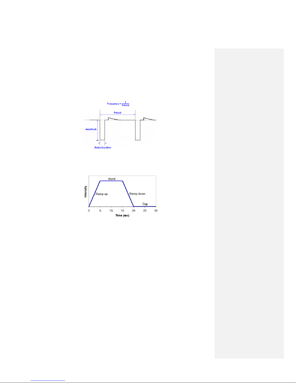
Amplitude – the level of current flowing during the stimulus pulse. The Amplitude is measured in
milliamperes (mA). See Figure G.1
G.1: Stimulus waveform; Two stimulus pulses are shown
Burst – the portion of a stimulation cycle during which stimulus pulses are delivered at the maximum
programmed amplitude and pulse duration (Figure G.2).
Figure G.2 One cycle of stimulation, composed of four periods:
ramp up, burst, ramp down, and gap.
Charge – The total magnitude of electrical charge delivered by the rectangular stimulus pulse. The per
pulse charge of a stimulus pulse in nanoCoulombs (nC) is equal to the product of Amplitude and Pulse
Duration (nC =mA x µs).
Cycle – the period of time for the ramp up, burst, ramp down, and gap periods of stimulation to each
occur once (Figure G.2).
Duty Cycle – the percent of time full stimulus pulses are being delivered during one cycle of stimulation.
(ramps are counted at half the actual time)
Electrode – a conductor in electrical contact with tissue to transfer electric current from a stimulator to
the body of a patient. The distal exposed metal portion of the Sprint MicroLead is the electrode.
Frequency – the number of stimulus pulses delivered per second on the (or each) channel / Lead.
Measured in Hertz (Hz). See Figure G.1.

Chapter 1: Introduction
5
| SPRINT® PNS System – Clinician Instruction for Use [L0090-MAN-000 Rev F]
Gap – the portion of a stimulation cycle during which stimulus pulses are not delivered (Figure G.2). (Not
applicable when duty cycle is set to 100%; i.e., when the pulse train continues at set value until
stimulation is stopped.)
Intensity - the strength of the stimulation delivered on a scale of 1.0 (minimum) to 100.0 (maximum).
The Intensity value (1 – 100) is mapped into clinically useful per pulse stimulus charges that allows
convenient control of the strength of stimulation.
Pulse Duration – the length of time one stimulus pulse lasts. Measured in microseconds (sec). See
Figure G.1.
Ramp Down – the period of time during the stimulus cycle when stimulus pulse Amplitude is decreasing
from its maximum value to zero (Figure G.2). (Not applicable when duty cycle is 100%; i.e., when the
pulse train continues at set value until stimulation is stopped.)
Ramp Up – the period of time during the stimulus cycle when is increasing from zero to its maximum
value (Figure G.2). (Not applicable when duty cycle is 100%; i.e., when the pulse train continues at set
value until stimulation is stopped.)
Chapter 1: Introduction
6
| SPRINT
®
PNS System – Clinician Instruction for Use [L0090-MAN-000 Rev F]
1 Introduction
1.1) Indications for Use
The SPRINT
®
Peripheral Nerve Stimulation (PNS) System is indicated for up to 60 days in the back and/or
extremities for:
- Symptomatic relief of chronic, intractable pain, post-surgical and post-traumatic acute pain;
- Symptomatic relief of post-traumatic pain;
- Symptomatic relief of post-operative pain.
The SPRINT
®
PNS System is not intended to treat pain in the craniofacial region.
A randomized controlled trial failed to show that the SPRINT
®
PNS System was effective for post-stroke
shoulder pain.
1.2) Contraindications
• Use of the SPRINT
®
PNS System is contraindicated for:
- Patients who have a Deep Brain Stimulation (DBS) system.
- Patients who have an implanted active cardiac implant (e.g. pacemaker or defibrillator).
- Patients who have any other implantable neuro-stimulator whose stimulus current pathway
may overlap with that of the SPRINT System.
- Patients who require Magnetic Resonance Imaging (MRI). The SPRINT
®
MicroLead and other
SPRINT components must be removed from the body before an MRI.
- Patients who have a tape or adhesive allergy.
1.3) Warnings
Refer to the warnings below before using the system. Additional warnings specific to home use are
included in the Patient Instructions for Use (Section 2: Important Safeguards).
SPRINT PNS System placement
The Sprint PNS System is for use in the back and/or extremities.
The Sprint PNS System is not intended to treat pain in the
craniofacial region.
Do not place the SPRINT Mounting Pad on the head or on the
front of the throat. Stimulation in these areas may cause severe
muscle spasms resulting in closure of the airway, difficulty
breathing, or adverse effects on heart rhythm or blood pressure.
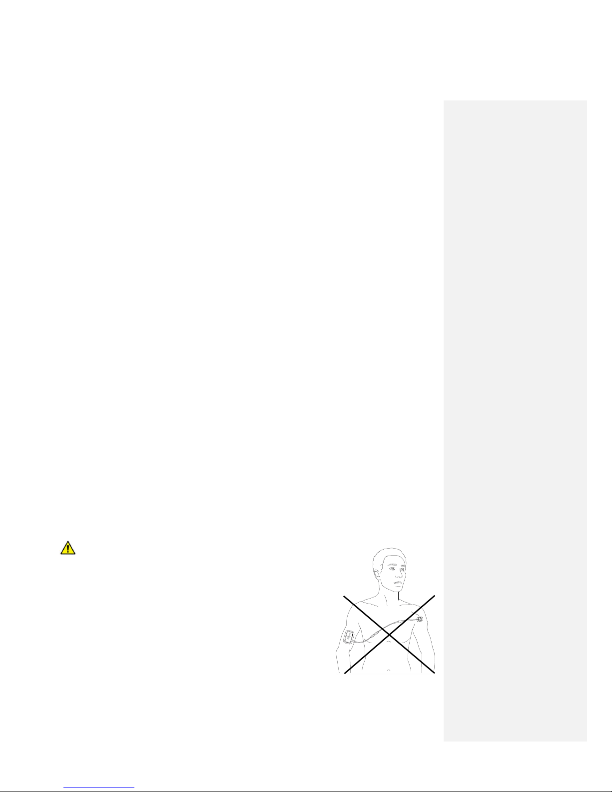
Do not apply stimulation across the chest; introduction of
electrical current into the chest may cause rhythm disturbances
to the heart, which could be lethal.
Chapter 1: Introduction
7
| SPRINT
®
PNS System – Clinician Instruction for Use [L0090-MAN-000 Rev F]
Stimulating Probe or MicroLead placement near vital structures (i.e. major arteries, visceral
organs, pleural cavity, etc.) – Use imaging (e.g., ultrasound) to guide placement of the Stimulating Probe
and MicroLead when placing near an artery or organ to decrease the risk of puncture.
Pregnancy – Safety for use during pregnancy has not been established.
Pediatric Use – Safety and effectiveness have not been established for pediatric use (i.e., in a
patient 21 years of age or younger).
Infection Control – Follow all applicable infection control procedures. Standard aseptic technique
should be followed. Failure to follow infection control procedures could lead to an increased risk of
infection.
Explosive or Flammable Gases – To avoid ignition, do not use the SPRINT
®
PNS System in the
presence of flammable anesthetic mixtures with air or with oxygen.
Diathermy – Patients with a SPRINT MicroLead CANNOT undergo therapy using any shortwave
diathermy, microwave diathermy, or therapeutic ultrasound diathermy anywhere on their body. Energy
from diathermy can heat the Lead and cause severe injury.
Electrocautery – Simultaneous connection the SPRINT System and high frequency surgical
equipment (electrocautery) to a patient may result in burns at the site of the electrode at the tip (barb)
of the MicroLead and/or at the Mounting Pad.
Do not reuse the SPRINT PNS System – the SPRINT PNS System is a single patient device. Use of
the system, or any component thereof except the Clinical Programmer, by more than one person may
result in infection, damage to the system, or failure of the System to operate. This does NOT include the
Clinical Programmer Tablet or Clinical Programmer Charger, which are non-sterile, reusable system
components for use by medical professionals only and should not be allowed to come into contact with
patients.
Clotting disorders – Do not place the Stimulating Probe or MicroLead in any patient who has a
bleeding or clotting disorder. Bleeding risk should also be considered in patients taking anticoagulant
therapy.
Anesthetic Block - Use caution when placing a Stimulating Probe or MicroLead in patients who
have recently received an anesthetic block in the area of the targeted PNS therapy. These patients may
have an altered response to stimulation.
Modifying the SPRINT System – Do not take apart or modify any component of the Sprint System.
Doing so may result in injury to the patient or damage to the System.
Do not use any component of the SPRINT System with a component that is not part of the
SPRINT System. Doing so may result in injury or damage to the System. This is also true of the AC
Power Adapters supplied; a replacement device must have the same specifications and safety
Certifications.

Chapter 1: Introduction
8
| SPRINT® PNS System – Clinician Instruction for Use [L0090-MAN-000 Rev F]
1.4) Precautions
Refer to the precautions below before using the system. Additional precautions specific to home use are
included in the Patient Instructions for Use.
Painful stimulation – If stimulation feels painful to the patient, decrease the intensity or turn it off. If it
is not possible to turn stimulation off, remove the Pulse Generator from the Mounting Pad (this will
force the stimulation to turn off).
Use during surgery and delivering stimulation near a surgical incision - If a Lead is to be placed prior to
a surgical procedure, then the lead should be placed away from the expected surgical incision as well as
other areas that may be impacted by supplies used during the surgical procedure (e.g., tourniquet). The
SPRINT Pulse Generator, Mounting Pad, and cables should be removed prior to any surgery, and the
MicroLead and MicroLead Connector should be secured beneath sterile bandages. Use caution when
delivering stimulation near an unhealed surgical incision. Doing so could cause a surgical incision to re-
open or fail to heal properly.
Mounting Pad Placement – Mounting Pads should only be placed on clean healthy skin. Placement on
unhealthy skin (i.e. irritated or injured skin, rashes or wounds) may further irritate the area and cause
stimulation to feel different or be uncomfortable. It is acceptable to apply the Mounting Pad to a
birthmark and hair baring areas. If the patient experiences sensitivity or poor adhesion, move the
Mounting Pad to another location.
MicroLead Connector and Mounting Cradle Placement – To reduce the risk of infection, do not place
the MicroLead Connector or the Mounting Cradle directly on top of the MicroLead exit site.
Electronic medical equipment – The System may interfere with patient monitoring equipment or other
physiological instruments. Always turn off and disconnect the stimulator before any unrelated medical
tests or procedures.
Broken or disconnected MicroLead or cable – Avoid pulling on the MicroLead or anything connected to
it, which may cause the MicroLead to be pulled out. If the MicroLead or any cable breaks or becomes
disconnected, stop stimulation and replace the broken component or reconnect the components, as
applicable. A broken or disconnected MicroLead or cable may deliver a safe, but uncomfortable
stimulation lasting a few seconds.
Portable and mobile Radio Frequency (RF) communications – Portable and mobile Radio Frequency
(RF) communications equipment can interfere with the stimulator. Do not use such equipment while
using the System. For additional information on RF communications, contact SPR Therapeutics.
• System interference from other radio frequency devices: In the presence of other radio frequency
devices (including but not limited to cell phones, two-way handheld radios, and other Bluetooth
devices), it is possible that the Clinical Programmer will have difficulty communicating with the Pulse
Generator over its Bluetooth wireless link. This may result in delay or pauses between issuing a
command and a response from and change in the operation of the Pulse Generator.
Electromagnetic Interference (EMI) – The SPRINT® PNS System is not likely to cause any interference in
nearby electronic equipment through Electromagnetic Interference (EMI) other than Bluetooth
interactions (complies with CISPR 11, Type B).
• System interference with nearby devices: As with most medical electronic equipment,
operation of the SPRINT® PNS System has the potential to interfere with the operation of
nearby radio frequency devices (for example, radios, televisions, wireless phones, headsets,
Chapter 1: Introduction
9
| SPRINT® PNS System – Clinician Instruction for Use [L0090-MAN-000 Rev F]
and digital appliances). The System incorporates Bluetooth wireless communications
features in the Pulse Generator and the Hand-Held Remote. Although commonly used with
many personal digital appliances, too many Bluetooth equipped devices in use at the same
time within a few feet of each other can disrupts the operation of one or more of those
devices.
• If moving away from another device reduces or eliminates the problem, it is likely that the
System is interfering with the other device. Similarly, if the problem is only observed while
you are using the Hand-Held Remote to monitor or control the Pulse Generator, it is likely
that the System is interfering with the other device. You should move or orient yourself such
that the SPRINT® PNS System is not interfering with the other device.
• Nearby device interference with the System: As with most medical electronic equipment,
operation of the SPRINT® PNS System has the potential to be disrupted by the operation of
other nearby radio frequency devices (for example, cellular telephones, handheld two-way
radios used by emergency or utility service personnel, broadcast radio and television
transmitters, and amateur radio transmitters).
• Such a disruption is most likely to cause either an inability to use (or a pause or delay in
using) the Hand-Held Remote to control the Pulse Generator OR to cause a temporary
change to stimulation being delivered (for example missing pulses for a short period of time)
or turning the stimulation OFF.
• Portable RF communications equipment (especially cell phones but including antennas and
antenna cables) should not be used closer than 30cm (12 inches) to the Pulse Generator, the
Hand-Held Remote, or the Clinical Programmer. If disruption occurs, the SPRINT system will
not be damaged and there is no risk of injury to the patient.
• In all cases, stimulation can be turned OFF by pressing the button on the Pulse Generator, or
by removing the Pulse Generator from the Mounting Pad or unplugging the cables to the
Pulse Generator. If the cause of the interference is suspected, you should physically separate
yourself from the source of the interference or avoid using the interfering device at the
same time as the SPRINT® PNS System.
• FCC Compliance: This device complies with part 15 of the FCC Rules. Operation is subject to
the following two conditions: (1) This device may not cause harmful interference, and (2)
this device must accept any interference received, including interference that may cause
undesired operation.
• Changes or modifications made to the system or system components not expressly approved
by SPR Therapeutics will void the authority to operate the system.
• The FCC ID of the Hand-held Remote (2AO2X-9620) is displayed on the initial splash screen
after being unlocked. The FCC ID of the Pulse Generator (2AO2X-9620) is located on the label
on the back the device.
• For more details on Electromagnetic Interference contact SPR Therapeutics (see Appendix C:
Contacting SPR Therapeutics).
Handle the SPRINT® PNS System with care – Rough handling, including dropping on the ground or being
crushed, can damage the SPRINT System.
MicroLead Movement – Do not apply force to the SPRINT MicroLead. Pulling on the MicroLead will
cause it to move or dislodge. A change in sensation (including intensity or location), response (including
location of response), or stimulus intensity required to foster pain relief may indicate that the MicroLead
has moved. If the MicroLead has moved and the desired response is no longer attained after testing the
full range of stimulus parameters available, MicroLead replacement may be necessary.
Kommentar [MW2]:
Required
statement per 47 CFR 15.21
Formaterat: Teckensnitt:9 pt, Fet
Formaterat: Teckensnitt:10 pt, Inte
Fet
Formaterat: Teckensnitt:10 pt, Inte
Fet
Formaterat: Teckensnitt:10 pt, Inte
Fet
Kommentar [MW3]:
Required per 47
CFR 2.935
Formaterat: Teckensnitt:10 pt, Inte
Fet
Chapter 1: Introduction
10
| SPRINT® PNS System – Clinician Instruction for Use [L0090-MAN-000 Rev F]
Not water proof – Do not submerge any components of the SPRINT System in water, alcohol, other
fluids, or dust. Exposure to fluids or dust could damage the System and cause it to stop operating.
Adding a drop of water to the pad before its use to improve adhesion is acceptable.
Battery Care – The batteries may become unsafe if disassembled, shorted (when battery connections
contact metal), or exposed to high temperature or fire. The materials within the battery can discolor
skin and are not safe to ingest. Do not leave the SPRINT System in a closed car or truck in hot summer
temperatures.
Long Term Effects – The long-term effects of electrical stimulation are unknown. The use of this system
is intended for up to 60 days.
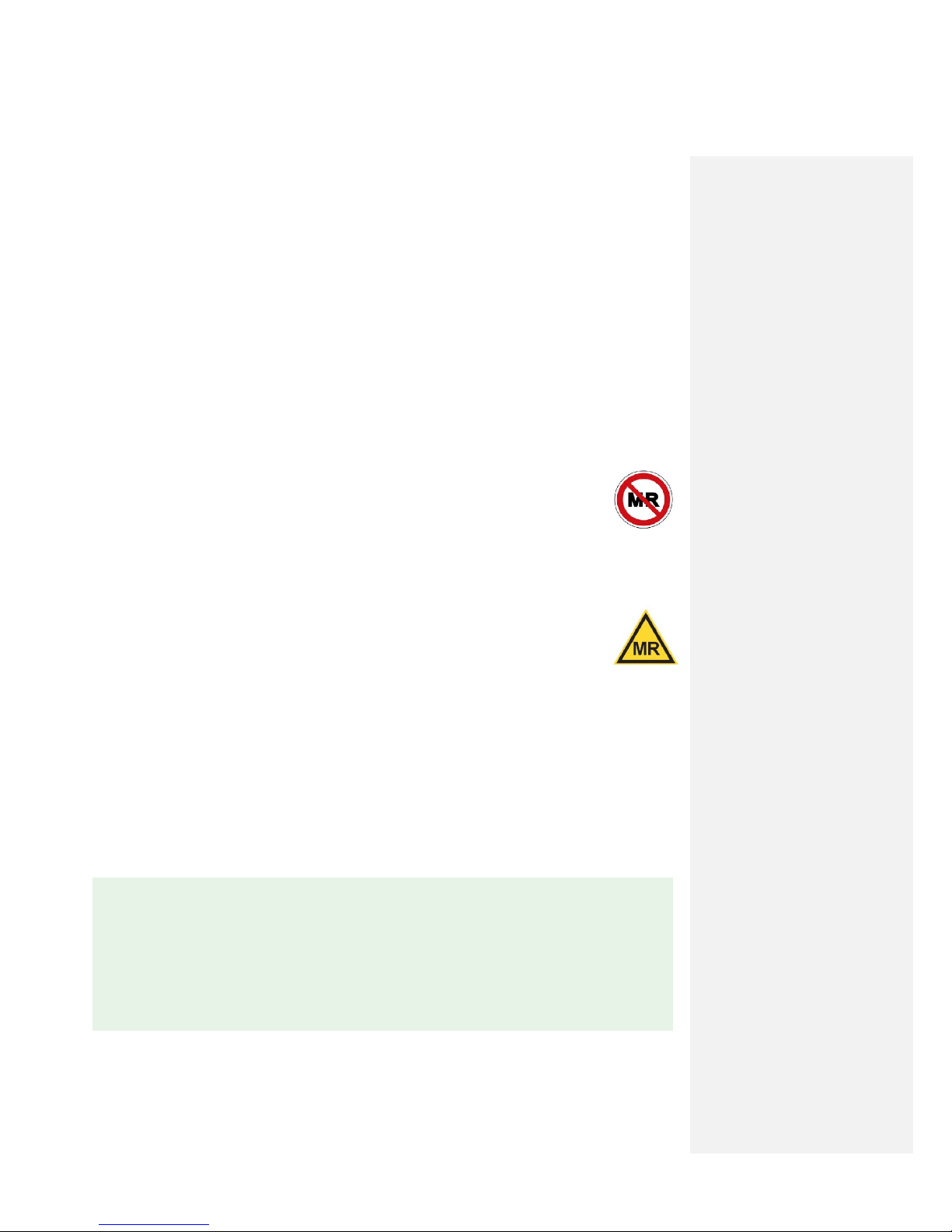
1.5) MRI Safety Information
The SPRINT® PNS System is MR Unsafe - All MRI procedures, no matter the anatomic site,
are contraindicated for patients with the SPRINT® PNS System. Exposure can cause tissue
heating and injury or unwanted stimulation. Remove the lead and all other system
components from the patient before an MRI examination is performed.
In the case of a lead fracture beneath the skin that results in a retained lead fragment, an MRI
examination is safe to perform under the conditions described in the MR Conditional statement below.
A Retained Lead Fragment ONLY is MR conditional
Non-clinical testing demonstrated that a retained lead fragment entirely beneath the skin
is conditionally MR-safe. A patient with a retained lead fragment can be safely scanned in
an MR system under the following conditions:
Static magnetic field of 1.5 Tesla
Maximum spatial gradient magnetic field of 1,000 Gauss/cm (10 T/m)
Maximum MR system-reported whole body averaged specific absorption rate (SAR) of 2 W/kg
for 15 minutes of scanning (Normal Operating Mode)
Under these scan conditions, the fragment is expected to produce a maximum temperature rise of less
than 3.3°C after 15 minutes of continuous scanning.
In non-clinical testing, the image artifact caused by a fragment extends approximately 7 mm from the
fragment when imaged using a gradient echo pulse sequence and a 1.5 Tesla MR system.
✎ NOTE: There should be no section of lead visible above the skin.
✎ NOTE: If a lead is placed in an individual with an existing retained lead fragment, the new
lead should not be placed in a location where it could touch the original lead fragment. During
MRI, two lead fragments touching each other can result in an increase in temperature of the
lead fragments and surrounding tissue where they touch.
Chapter 2: System Overview
11
| SPRINT® PNS System – Clinician Instruction for Use [L0090-MAN-000 Rev F]
2 System Overview
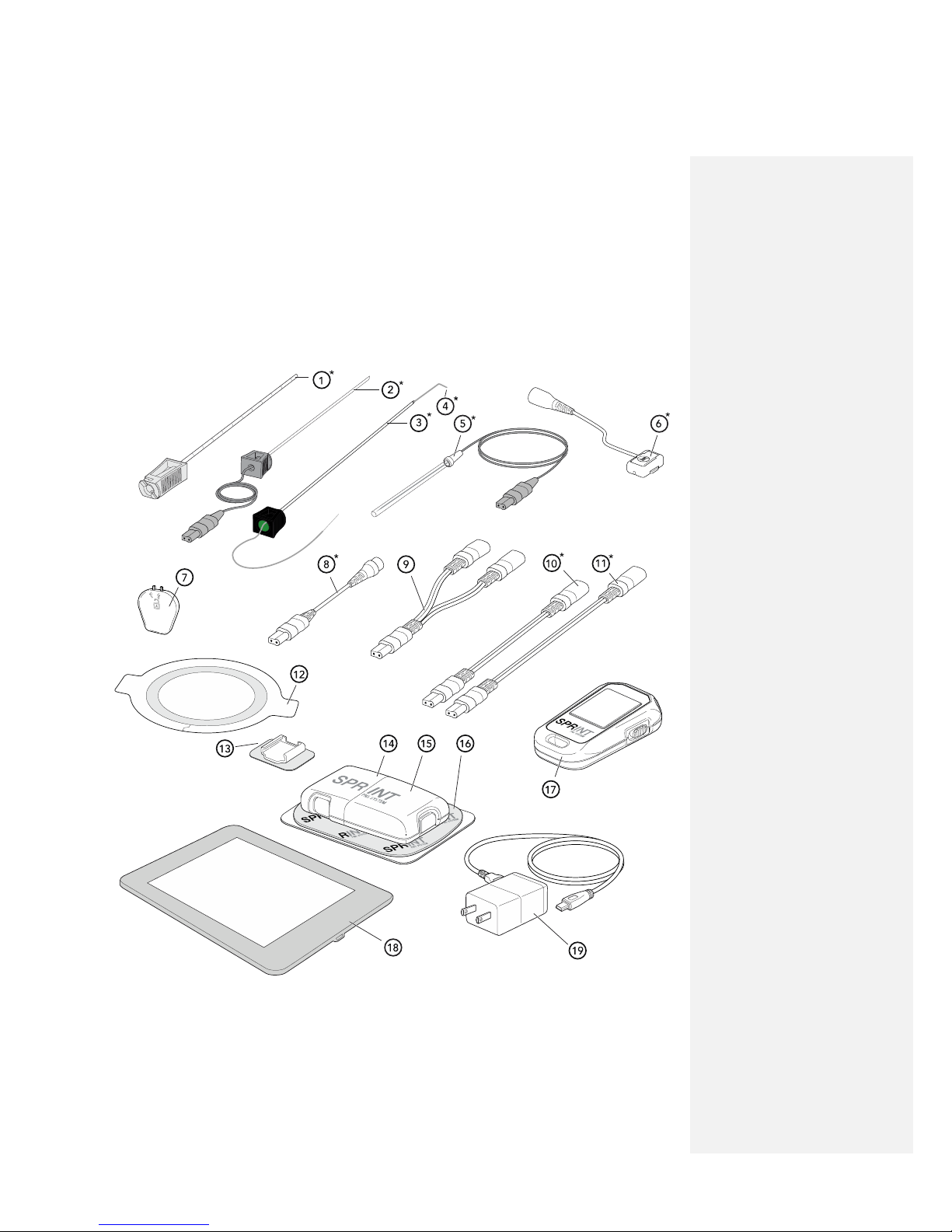
2.1) System Components
The SPRINT® PNS System is made up of sterile and non-sterile components.
* Indicates that two (2) of each component will be included for a dual lead system.
✎ NOTE: Components not shown to scale.

Chapter 2: System Overview
12
| SPRINT® PNS System – Clinician Instruction for Use [L0090-MAN-000 Rev F]
Sterile Components
1. Percutaneous Sleeve: Part of the MicroLead™ OnePass Introducer™ System, the Percutaneous
Sleeve is used for testing stimulation and placing the MicroLead.
2. Stimulating Probe: Part of the MicroLead™ OnePass Introducer™ System, the Stimulating Probe
is used to test stimulation prior to placing the MicroLead.
3. MicroLead Introducer: Part of the MicroLead™ OnePass Introducer™ System, the MicroLead
Introducer is used to insert the MicroLead.
4. MicroLead: The MicroLead is a fine wire with anchoring tip and electrode contact suitable for
placement through the skin into tissue in proximity to a target nerve.
5. Stimulating Needle: Utilized as an alternative to the MicroLead™ OnePass Introducer™ System,
the Stimulating Needle is a small gauge needle with a stimulating electrode tip used as an option
to identify the optimal site for MicroLead placement.
6. MicroLead Connector (Light Gray & Dark Gray): The connecting piece that creates an efficient
electrical connection between the MicroLead and the Pulse Generator. (Dual-Lead Systems
come with two MicroLead Connectors, one with a light gray cable connector (Light Gray) and the
other with a dark gray cable connector (Dark Gray).)
7. MicroLead Connector Key: The key that unlocks the MicroLead Connector when re-connection
by the clinician is desired.
8. Magnetic Coupler (Light Gray & Dark Gray) Breakaway system between the MicroLead
Connector and the Pulse Generator intended to separate and minimize the potential for
MicroLead dislodgement. (Dual-Lead Systems come with two Magnetic Couplers, one with a
light gray cable connector (Light Gray) and the other with a dark gray cable connector (Dark
Gray).)
9. Dual-Lead Adapter: In a Dual-Lead configuration, this allows two MicroLead connectors to
attach to one port on the Pulse Generator. (Only included in Dual-Lead SPRINT extensa™
System)
10. Short Extension: Allows for 15 cm of extra length between the Magnetic Coupler and the Pulse
Generator. (Not necessary for use)
11. Long Extension: Allows for 36 cm of extra length between the Magnetic Coupler and the Pulse
Generator. (Not necessary for use)
Non-Sterile Components
12. Waterproof Bandage: Intended to keep the lead exit site clean and dry and to minimize the risk
for lead dislodgement.

Chapter 2: System Overview
13
| SPRINT® PNS System – Clinician Instruction for Use [L0090-MAN-000 Rev F]
13. Mounting Cradle: Adhesive pad that holds the MicroLead Connector in place near the
MicroLead exit site to minimize the potential for lead dislodgement.
14. Rechargeable Battery: The power source used to run the Pulse Generator.
15. Pulse Generator: The device that produces the electrical pulses used to deliver stimulation
therapy.
16. Mounting Pad: Connects the Pulse Generator to the skin. One side of the Pad has an adhesive
gel, exposed by removing the clear liner. The non-sticky side of the Pad has two snaps that
connect to the Pulse Generator.
17. Hand-Held Remote: The tool that allows patients and clinicians to communicate to the Pulse
Generator via Bluetooth® allowing the clinician to program the Pulse Generator and the patient
to make safe, clinician-prescribed adjustments to their therapy at home.
18. Clinical Programmer Tablet: Touch screen tablet provides an alternative to the Hand-held
Remote while providing access to advanced programing functions. Not intended for patient use.
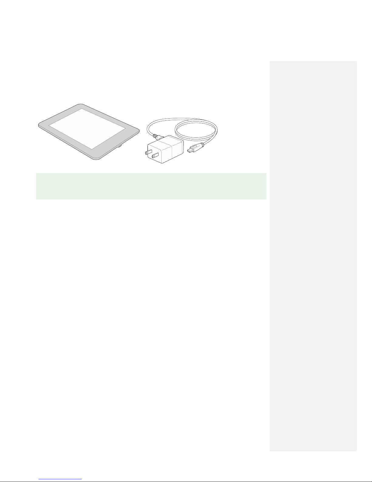
19. Clinical Programmer Charger: USB cord and AC adapter plug used to recharge the Clinical
Programmer.
20. Patient Case: Includes Recharging Base and Power Supply (recharges the Rechargeable Batteries
for the Pulse Generator), extra Rechargeable Battery, Waterproof Bandages, Mounting Cradles,
Mounting Pads, and Patient Instructions for Use and Quick Start Guide documents.
21. Patient Disposable Supplies: Extra Waterproof Bandages, Mounting Cradles, and Mounting Pads
are supplied in addition to what is included inside the Patient Case.
2.2) Programming Tools Overview
Initial programming of the Pulse Generator may be performed using either the Hand-Held Remote or
the Clinical Programmer (both provided non-sterile). Both the Hand-Held remote and the Clinical
Programmer communicate wirelessly with the Pulse Generator.
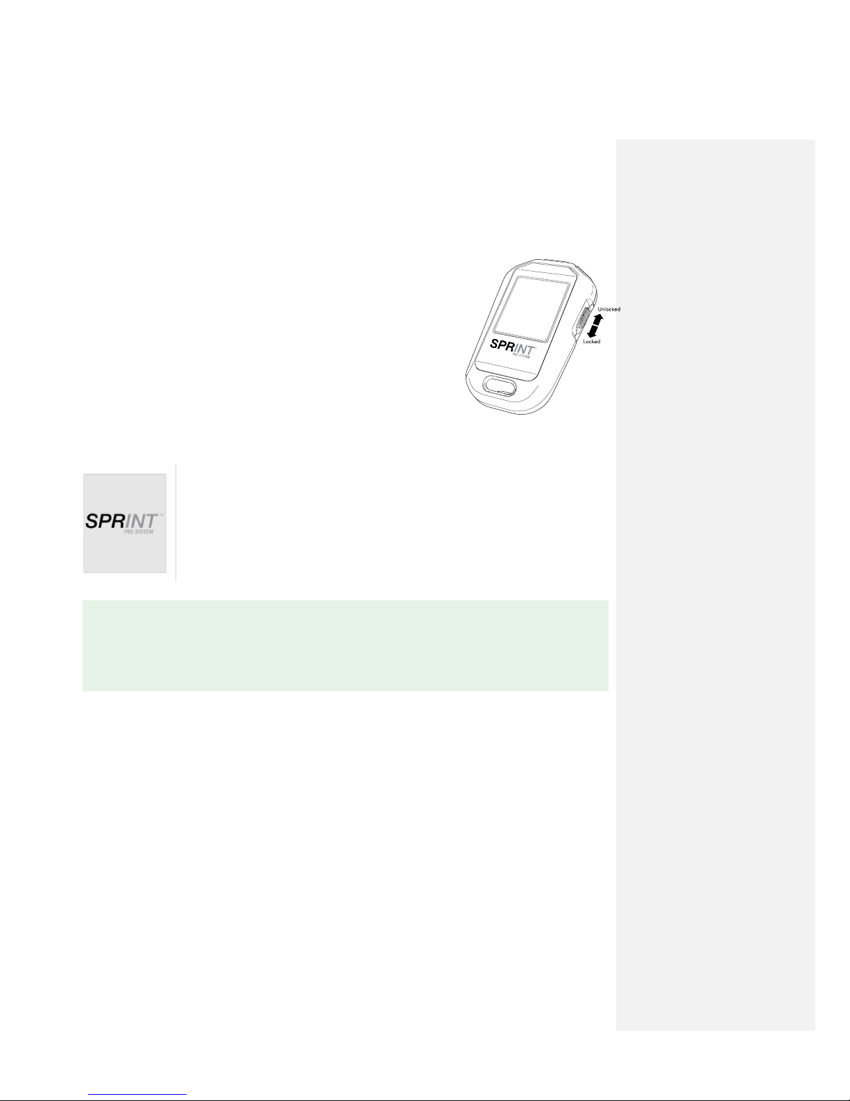
2.2.1) Hand-Held Remote
The Hand-Held remote is pre-paired to connect only with the packaged Pulse Generator. The Hand-Held
remote is operated using the buttons positioned at the top of the device. The variable functions of the
buttons on the top of the remote correlate with the symbols or messages displayed on the screen below
each respective button.
The Hand-Held Remote may be used in two modes:
By the clinician during MicroLead placement procedure.
By the patient during home use.
Chapter 2: System Overview
14
| SPRINT
®
PNS System – Clinician Instruction for Use [L0090-MAN-000 Rev F]
The Hand-Held Remote is not able to access some programming features that are available via the
Clinical Programmer.
To unlock the Hand-Held Remote:
Move the Lock/Unlock Switch to the up position.
To lock the Hand-Held Remote:
Move the Lock/Unlock Switch to the down position.
To wake up the Hand-Held Remote:
The Hand-Held Remote will automatically go to sleep after a period of inactivity. To wake up the remote,
press any button or toggle the Lock/Unlock Switch to the Up/Unlocked position.
The startup screen will show for
a few seconds while the remote
is connecting to the Pulse
Generator.
2.2.2) Clinical Programmer
The Clinical Programmer is a tablet that allows the clinician to operate and program the Pulse
Generator. The Clinical Programmer is not intended for use by patients and is non-sterile. If the clinician
wishes to use the Clinical Programmer during the MicroLead placement procedure, it is recommended
that an assistant be present to handle the Clinical Programmer while the clinician is in the sterile field.
Ensure that the Clinical Programmer is fully charged prior to the start of a programming session.
The Clinical Programmer should be cleaned in the same manner that any consumer electronic device is
cleaned.
✎ NOTE: The Hand-Held Remote is shipped with a thin plastic tab in the battery compartment
which prevents the Remote battery from draining during storage and shipment. Prior to use of
the Hand-Held Remote, this tab must be removed by pulling on it. If not removed, the Hand-Held
Remote will not operate.
Chapter 2: System Overview
15
| SPRINT® PNS System – Clinician Instruction for Use [L0090-MAN-000 Rev F]
✎ NOTE: When stored for extended periods of time, the Clinical Programmer should be stored
in a cool, dry location.
Chapter 3: Procedure Preparation
16
| SPRINT
®
PNS System – Clinician Instruction for Use [L0090-MAN-000 Rev F]
3 Procedure Preparation
3.1) Procedural Precautions
These instructions are intended to provide the clinician with considerations, but are not intended as
definitive descriptions of the lead placement technique. The clinician, based on standard clinical
practice, should determine lead placement decisions and technique.
MicroLead Insertion Site Considerations:
As necessary, the lead insertion site should be adjusted to meet these criteria:
Leads are only intended to be placed in the back and/or extremities.
The SPRINT System is not intended to treat pain in the craniofacial region.
Consider where the MicroLead Connector and Pulse Generator will be situated in relation to the
lead exit site(s). The locations of these components should assure that tension on the lead is
minimized and that the Pulse Generator is in a location that is comfortable and easily accessible
by the patient or caregiver.
Consider if the MicroLead or the stimulation it delivers will be susceptible to postural changes,
pressure from body weight, clothing, etc.
Consider the cleanliness and ease of access to clean the insertion site.
If a Lead is to be placed prior to a surgical procedure, then the lead should be placed away from
the expected surgical incision as well as other areas that may be impacted by supplies used
during the surgical procedure (e.g., tourniquet).
Explosive or Flammable Gases – To avoid ignition, do not use the SPRINT
®
PNS System in
the presence of flammable anesthetic mixtures with air or with oxygen.
Infection Control – Follow all applicable infection control procedures. Standard aseptic
technique should be followed. Failure to follow infection control procedures could lead to an
increased risk of infection.
Do not use a component of SPRINT
®
PNS System when:
The packaging has been pierced, damaged, or altered;
The component shows signs of damage; or
The “Use By” date has passed.

Chapter 3: Procedure Preparation
17
| SPRINT® PNS System – Clinician Instruction for Use [L0090-MAN-000 Rev F]
3.2) Gather Components
Inspect all packaging for any signs of damage and lay out the components for easy access.
Components provided for MicroLead Placement
Pulse Generator with Rechargeable Battery (non-sterile)
Mounting Pad (non-sterile)
Hand-Held Remote (non-sterile)
Clinical Programmer (non-sterile) (optional)
MicroLead™ OnePass Introducer™ System
o Percutaneous Sleeve
o Stimulating Probe
o MicroLead with MicroLead Introducer
Stimulating Needle (optional)
Connector Key
Waterproof Bandage(s)
Mounting Cradle(s) (non-sterile)
Short and Long Extension(s)
Dual Lead Adapter (for two lead configuration)
MicroLead Connector(s)
Magnetic Coupler(s)
3.3) Assemble Additional Supplies and Set up a Sterile Procedure Tray
Sterile surgical towels (2 packs) or similar to provide an area for sterile components
Sterile gloves
Preferred patient drape
Antiseptic (povidone-iodine or chlorhexidine) swabs (2 packs)
Local anesthetic and syringe/needle
Scissors
Sterile probe cover (if using ultrasound guidance)
Surgical marker pack with ruler (if using a Stimulating Needle instead of the MicroLead™
OnePass Introducer™ System)
3.4) Prepare the Patient Case
Ensure that the Patient Case is ready for patient use and includes all of the following:
Recharging Base and Power Supply
Second Rechargeable Battery
Waterproof Bandages
Mounting Cradles
Mounting Pads
Patient Instructions for Use
Patient Quick Start Guide
Chapter 3: Procedure Preparation
18
| SPRINT
®
PNS System – Clinician Instruction for Use [L0090-MAN-000 Rev F]
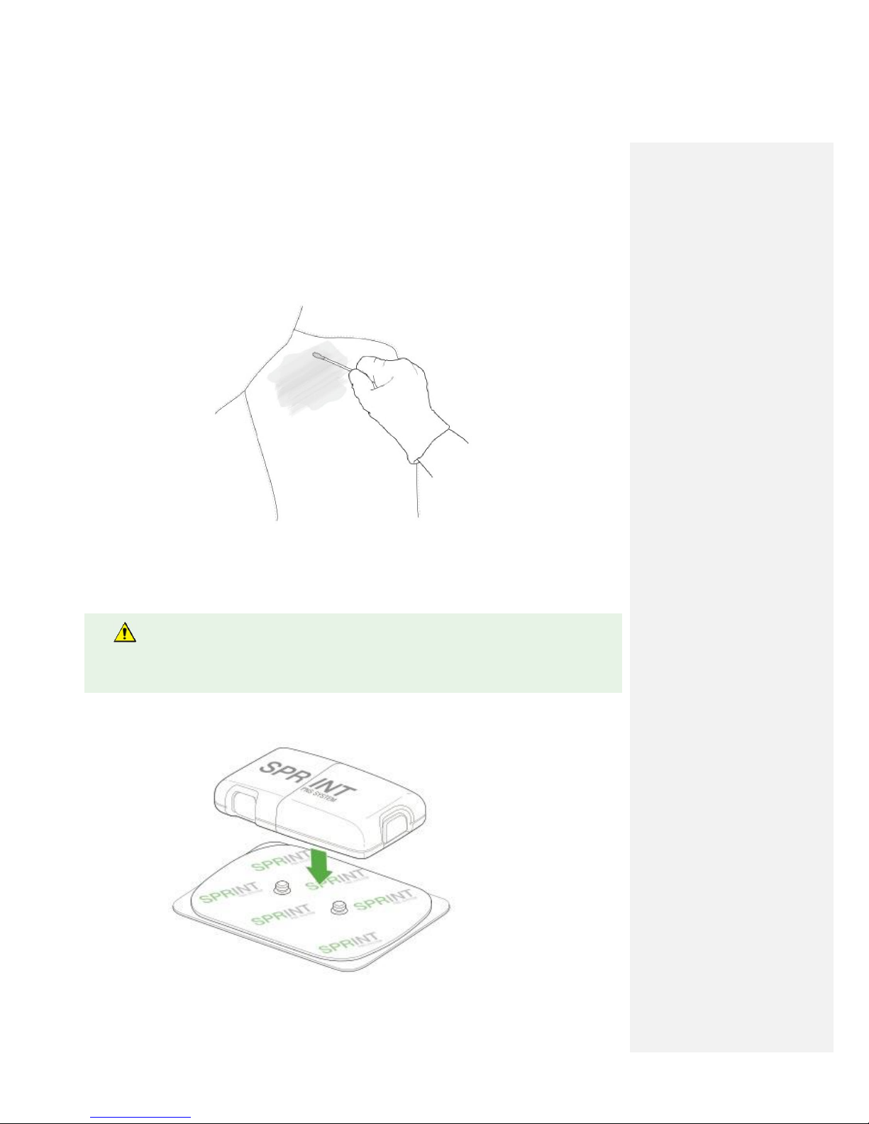
3.5) Prepare the MicroLead Exit Site(s)
1. With the patient appropriately positioned, clean the skin following your institution’s guidelines
for aseptic technique. Clip (do not shave) hair as necessary.
2. If desired, administer local anesthetic around the planned insertion site(s) for the MicroLead.
Local anesthesia may be provided at the discretion of the clinician. Anesthesia may be applied
subcutaneously (e.g., lidocaine), topically (e.g., EMLA cream), or both.
3.
Snap the Pulse Generator onto the Mounting Pad.
Do not administer the local anesthetic into deep tissues. Administering anesthetics close to
the terminal position of the electrode could affect the response to stimulation.
Chapter 3: Procedure Preparation
19
| SPRINT
®
PNS System – Clinician Instruction for Use [L0090-MAN-000 Rev F]
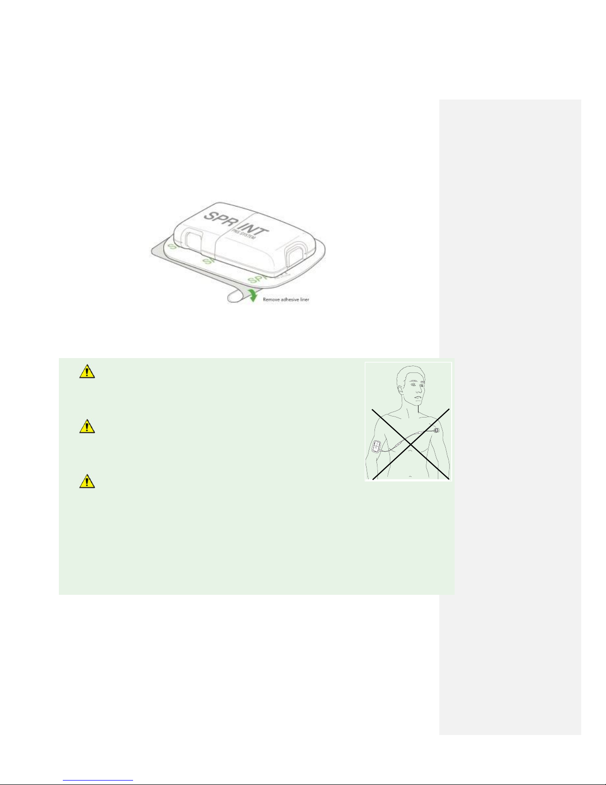
4. Remove Mounting Pad adhesive liner.
5.
Attach the Mounting Pad with Pulse Generator onto clean skin outside of the sterile field, in an
area away from motor points and away from the lead insertion site. Sensations of motor activity
may occur beneath the Mounting Pad and Pulse Generator.
Do not cross the chest when placing the Mounting Pad to prevent
passing current across the heart. The introduction of electrical current
into the chest may cause rhythm disturbances to the heart, which could
be lethal.
Do not place the Mounting Pad on the head or on the front of
the throat. Stimulation in these areas may cause severe muscle
spasms resulting in closure of the airway, difficulty breathing, or
adverse effects on heart rhythm or blood pressure.
Mounting Pads should only be placed on clean healthy skin.
Placement on unhealthy skin (i.e., irritated or injured skin, rashes or
wounds) may further irritate the area and cause stimulation to feel different or be uncomfortable. It is
acceptable to apply the Mounting Pad to a birthmark and hair baring areas. If the patient experiences
sensitivity or poor adhesion, move the Mounting Pad to another location.
Chapter 4: MicroLead Placement & System Set-Up
20
| SPRINT® PNS System – Clinician Instruction for Use [L0090-MAN-000 Rev F]
4 MicroLead Placement & System Set-up
4.1) Identifying Lead Placement Target using the OnePass Introducer™ System
1. Locate the target peripheral nerve. (see Appendix G: Lead Placement in Proximity to Peripheral
Nerves for example lead placements)
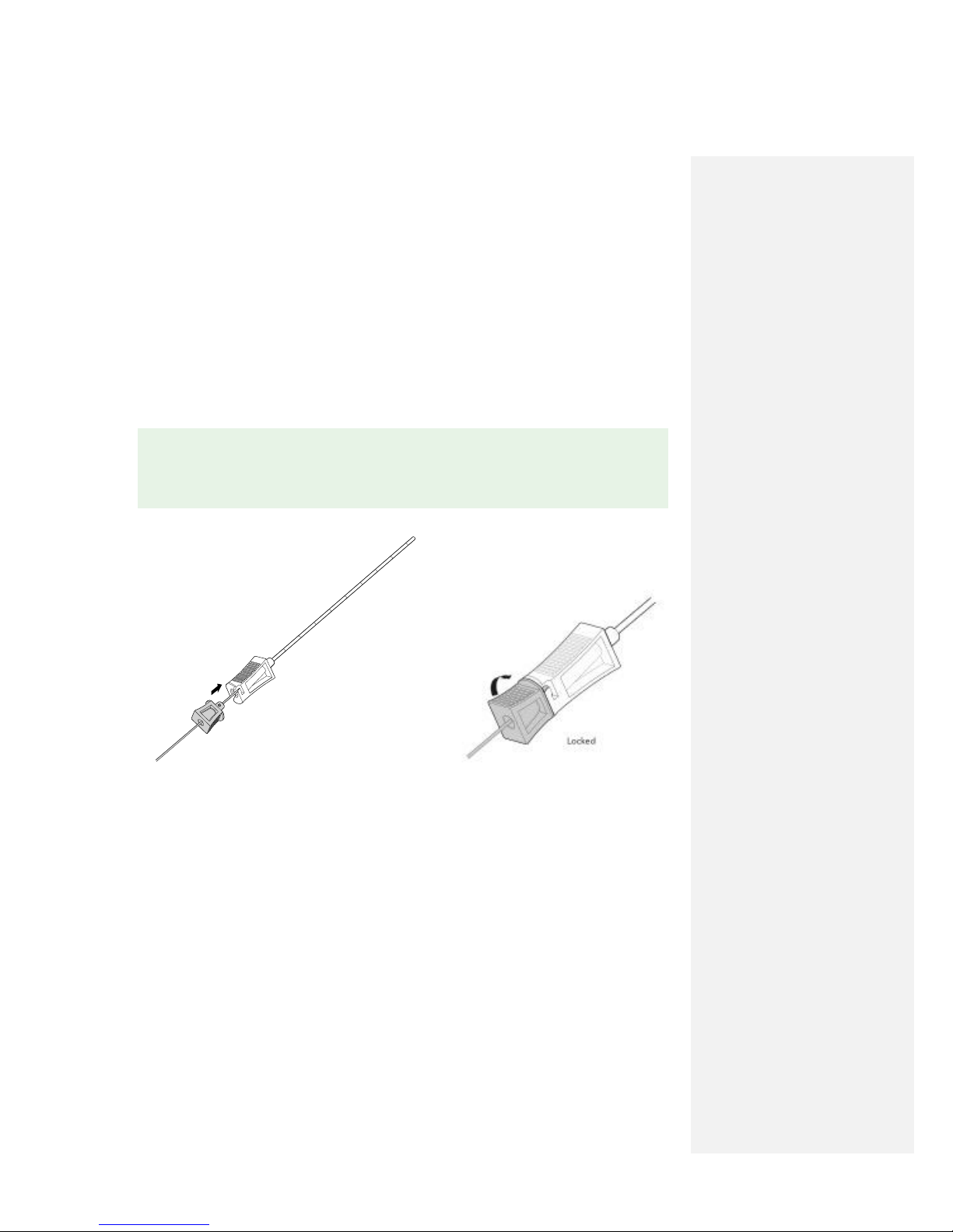
2. Insert the Stimulating Probe into the Percutaneous Sleeve. Align hub components and rotate the
Stimulating Probe clockwise to lock components together prior to insertion into the body.
✎ NOTE: If using the Stimulating Needle instead of the OnePass Introducer™ System to
test stimulation and place the MicroLead, see Appendix F: Using the Stimulating Needle for
MicroLead Placement Procedure.
Table of contents
Other SPR Therapeutics, Inc. Medical Equipment manuals


