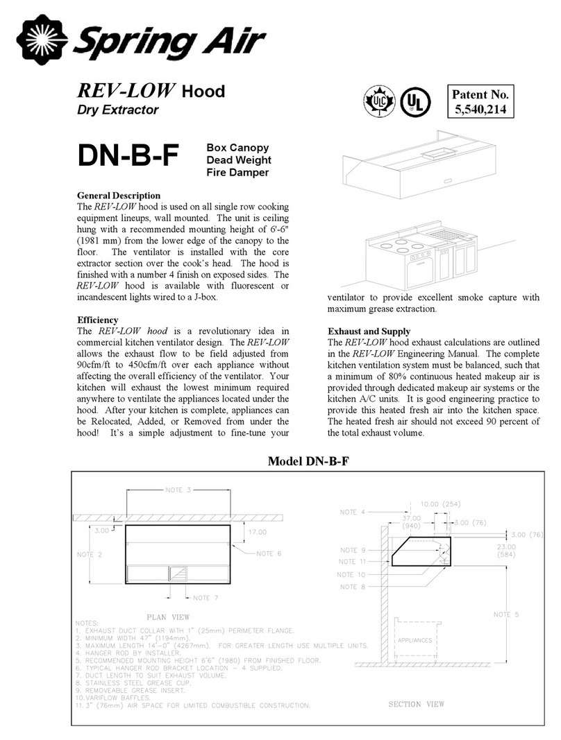
Spring Air Systems KES Enviro User manual

KES Enviro
Maintenance Manual
___________________________
Spring Air Systems Inc., Oakville, Ontario


KES Enviro Maintenance Manual
Table of Contents
Introduction....................................................................................... 1
The System...................................................................................... 1
Control System: Water Wash Ventilator SB, SBA Panels............... 2
Control System: Water Wash Ventilator AP, MP Panels.................. 4
Filter Hood or Dry Grease Extractor................................................. 5
Control Circuit.................................................................................. 7
Setting the Day and Time................................................................ 13
Setting the Weekday Fan “ON” and “OFF” Times............................ 14
Setting Weekend Operation............................................................. 15
Odor Spray Systems........................................................................ 15
Where to Purchase Filters................................................................ 19
Replacement Filter Equivalents........................................................ 19
Trouble Shooting.............................................................................. 20
KES Maintenance Schedule............................................................ 22
KES Enviro Start-Up Report............................................................. 24
Filter Frequency Chart...................................................................... 26


Enviro Maintenance Manual 2004
KES OPERATIONS AND MAINTENANCE MANUAL
INTRODUCTION
The SPRING AIR SYSTEMS INC. kitchen Enviro system (KES), Exhaust Cleaning Assembly for Kitchen
Exhaust Duct, “Enviro Unit” is ULC and UL listed for use in a commercial kitchen exhaust system. KES
units are available in sizes ranging from 1,000 CFM to 40,000 CFM for indoor or outdoor applications.
The primary function of a KES Enviro unit is to filter the grease, lint and dust particles and remove the odor
from the exhaust air.
The Underwriters’ Laboratories of Canada Limited (ULC) listing allows the use of non-NFPA-96 exhaust
ductwork after the exhaust air is discharged from the KES unit. In other words the discharge ductwork can
be treated similar to standard HVAC ducting. Also after the kitchen exhaust air has been treated with the
KES unit the exhaust can be discharged outdoors at low levels.
The Underwriters Laboratories Inc. (UL) listing allows the kitchen exhaust air to be discharge to atmosphere
at low levels.
Prior to any installation the installer must seek approval from the authorities having jurisdiction.
THE SYSTEM
The grease-laden air rises from the cooking equipment into a UL or ULC exhaust hood. The exhaust hood
removes some of the airborne grease particulate. Typically most micronand submicron particles escape
into the exhaust ductwork. The exhaust ducting is connected from the hood to the inlet of the KES Enviro
unit. This exhaust ductwork must be supplied and installed in accordance with the NFPA-96 code.
KES System Schematic
Figure 1
Within the KES unit the exhaust air travels through three stages of particulate filters:
1Two (2) inches pleated-30 percent ASHRAE 52-76 prefilters.
2Twenty-one (21) to twenty-two (22) inch bag-90 percent ASHRAE 52-76 filters.
3Twelve (12) inchesbox -95 percent DOP filters.
Discharge Ductwork
KESF Fan Box
Interconnecting Ductwork
KES-ISH Filter Box
NFPA-96 Ductwork
Listed Exhaust Hood
Water Wash
Panel
Remote
RPW(D) Panel
Appliance Line-up
Exhaust to
atmophere at
low level

Enviro Maintenance Manual 2004
Once through the particulate filter sections the exhaust air enters the optional odor removal section. The
odor section is only required when discharging cooking smells may be offensive. This section consists of
two optional odor removal systems.
1.Odor Cells filled with activated alumina impregnated with potassium permanganate. The odor is controlled
through a combination of sorption and the chemical modification of the gaseous contaminates. The
odor media is non-toxic and non-flammable.
1.Odor spray solution. The odor is control by spraying an odor reducer into the exhaust air stream
intermittently during the operation of the cooking systems.
2. KES-ISH and KESF Enviro components
Figure 2
The exhaust air is discharged from the KES unit through a single width, single inlet (SWSI) or double width,
double inlet (DWDI) exhaust fan. The discharge ductwork transfers the exhaust air outdoors.
CONTROL SYSTEM
Water Wash Ventilator System: SB, SBA Panels
The KES unit off/on operation is controlled from the SB, or SBA water wash ventilator control panel. Power
is fed to the RPW10 panel through terminals 1 & 4. When the fan selector switch on the water wash control
panel closes a signal is sent through terminal 3 to the RPW10 panel to activate the KES unit.
ALL REMOTE ELECTRIAL WIRING
AND NATIONAL CODE REQUIREMENTS
SHALL CONFORM TO ALL LOCAL
NOTE 1:
INTERNAL WIRING BY SPRING AIR
CURCUIT BREAKER
HOT WATER SOLENOID
1 2
Q1
H
B
Q2
1 2 1 2
Q3
1 2
Q4
LOGO!
Mo 09:00
01. 20. 03
LN
ESC OK
I4I1 I2 I3 I5 I6 I7
FAN SWITCH
OFF/ON
FAN PILOT
OPTIONAL COLD
WATER SOLENOID
PUMP
WASH PILOT
DETERGENT
G
7
1
C
I8
4
4
4
8
9
3
9
8
4
9
4
7
1
1
1
3
4
1
TWO (2) WIRES TO THE
HEAD 120V/1/60 - 1A.
WET CHEMICAL CONTROL
END SWITCH
WHITE
RED
(OPTIONAL) POWER SUPPLY TO SUPPLY FAN
MOTOR STARTER - 120V/1/60 - 2 AMPS MAXIMUM
(OPTIONAL) THREE (3) WIRES TO SUPPLY AIR MOTORIZED
SHUTOFF DAMPER AND END SWITCH 120V/1/60
PANEL - 120V/1/60 - 5 AMPS MAXIMUM.
POWER SUPPLY TO THE SB10H/C PANEL
24 HOURS/DAY - 120V/1/60 - 15 AMPS
THREE (3) WIRES TO THE KES UNIT RPW10 CONTROL
NORMALLY OPEN
2 AMPS MAXIMUM.
REMOTE WIRING BY TRADES
Typical KES wiring to SB10C water wash panel
Figure 3
KES-ISH
Fire Damper
Box Filter
Exhaust Fan
Odour Removal Section
EXHAUST OUTLET
TO THE OUTDOORS TO THE KESF FAN
EXHAUST OUTLET
KESF
Bag Filter
2 inch prefilter
Pressure switches
LV-10 Panel
FROM THE HOOD
EXHAUST INLET

Enviro Maintenance Manual 2004
The “NORMAL” operation pilot energizes on the RPW10 remote kitchen annunciation panel. After 30
seconds the RPW10 control circuit is activated. The RPW10 is a stainless steel panel located remote from
the SB or SBA panel. See Figure 5 for RPW10 wiring and dimensions. The KES exhaust fan motor is
energized through the terminals 5 & 4 to the LV10 J-Box located on the KESF fan section. See figure 11 for
internal wiring of the LV10 J-box. See figure 3 or 5 for a SB water wash panel.
LOGO!
Mo 09:00
01. 20. 03
Typical KES wiring to SBA10C water wash panel
Figure 4
END SWITCH
NORMALLY OPEN
END SWITCH
NORMALLY OPEN
THREE (WIRES) TO THE WATER WASH CONTROL
TO KES UNIT LV10 PANEL ON FILTER
PANEL - 120V/1/60 - 10 AMPS
120V/1/60 - 10 AMPS.
BOX - TEN (10) WIRES
CONTROL HEAD, 120V/1/60 - 1AMP
TWO (2) WIRES TO THE WET CHEMICAL
SWITCH, 120V/1/60 - 1 AMP
MOTORIZED INLET DAMPER AND END
(OPTIONAL) THREE (3) WIRES TO
(OPTIONAL) POWER SUPPLY TO SUPPLY FAN
MOTOR STARTER, 120V/1/60 - 2 AMPS
DRY CONTACT FOR BUILDING FIRE ALARM
FIRE ANUNCIATION, 5 AMPS MAXIMUM, N/O
1
4
1
4
3
12
14
13
16
17
18
15
5
OVERIDE SWITCH
RPW10 ELECTRICAL DATA
15 AMP CURCUIT BREAKER
4
8
9
1
7
1
7R6
I4I3I1NI2
Q2Q1
RUN/STOP
21
Q4
21
21
Q3
21
WARNING
R6
NORMAL
FIRE
FILTER REMOVED
PREFILTER CLOGGED
BOX FILTER CLOGGED
BAG FILTER CLOGGED
I7 I8I6I5
OKESC
I3I2NLI1
Mo 09:00
LOGO!
01. 20. 03
I4
2
Q3
12
Q4Q2
1 2
Q1
21 1
L
AUX!
RED
WHITE
RED
WHITE
POWER SUPPLY FROM BREAKER PANEL
KES FAN/NORMAL OPERATION
FILTER OUT/LOW AIR
0DOR SPRAY UNIT
BOX FILTER CLOGGED
BAG FILTER CLOGGED
BMS START/STOP
FIRESTAT - HIGH LIMIT
PREFILTER CLOGGED
LV10 RESET
15
20&21
17
18
16
1&4
12
14
13
5
TERMINAL DESCRIPTION
LEGEND
POWER WIRING BY GENERAL CONTRACTOR
FACTORY WIRING BY SPRING AIR SYSTEMS
CONTROL WIRING BY MECHANICAL CONTACTOR
RPW10 Wiring Schematic
Figure 5

Enviro Maintenance Manual 2004
FILTER
NORMAL
PREFILTER
CLOGGED
BAG FILTER
CLOGGED
OVERIDE
BOX FILTER
CLOGGED
REMOVED
WARNING
FILTER
FIRE
14.0"
PANEL MOUNTING
HOLES LOCATED
IN PANEL BACK.
8.0"
5.0"
Remote RPW10 Panel Dimensions
Figure 6
Water Wash Ventilator System: AP, MP Panels
The KES unit off/on operation is controlled from the MP or AP water wash ventilator control panel. The fan
selector switch on the water wash control panel closes and sends power through terminals 3 & 4 to the
RPW10 remote panel to energize the exhaust fan through terminals 5 & 4 in the LV-10 J-Box. (The LV10 J-
Box is mounted on the KES-ISH filter section).
The “NORMAL” operation pilot energizes on the RPW10. After 30 seconds the KES control circuit within the
RPW10 remote panel is activated. See Figure 5 for RPW10 internal wiring. The exhaust fan motor is
energized through the terminals 9 & 4 to the motor starter located on the KESF fan section. See figure 11
for internal wiring of LV10 J-Box with RPW10 remote panel.
AUX!
LOGO!
01. 20. 03
Mo09:00
Typical KES wiring to AP20C water wash panel
Figure 7

Enviro Maintenance Manual 2004
Remote wiring of KES Enviro units with Water Wash Hood and Panel
Figure 8
Filter Hood or Dry Grease Extractor: RPD10 Remote Panel
The KES unit off/on operation is controlled from RPD10 remote annunciation panel. The fan selector switch
on the RPD10 remote panel closes and sends power through terminals 5 & 4 to the LV10 J-Box to energize
the exhaust fan circuit. (The LV10 J-Box is mounted on the KES-ISH filter section). The “NORMAL”
operation pilot on the RPD10 remote kitchen annunciation panel energizes and after 30 seconds the KES
control circuit within the RPD10 remote panel is activated. The exhaust fan motor is energized through the
terminals 5 & 4 to the motor starter. See figure 8 for the RPD10 remote panel wiring and figure 9 for
dimensions.
JUMPER MUST BE IN PLACE AS NOTED TO OPERATE FROM BMS
OPTIONAL BMS START/STOP - 120V/1/60
CLOSE CONTACT ACROSS 20&21 TO START UNIT
OPEN CONTACT ACROSS 20&21 TO STOP UNIT
RPD10 CONTROL PANEL - 120V/1/60 - 15 AMPS
TO KES UNIT LV10 PANEL ON FILTER
POWER SUPPLY TO THE KES UNIT
MOTOR STARTER, 120V/1/60 - 2 AMPS
(OPTIONAL) POWER SUPPLY TO SUPPLY FAN
FIRE ANUNCIATION, 5 AMPS MAXIMUM, N/O
DRY CONTACT FOR BUILDING FIRE ALARM
(OPTIONAL) THREE (3) WIRES TO
MOTORIZED INLET DAMPER AND END
SWITCH, 120V/1/60 - 1 AMP
TWO (2) WIRES TO THE WET CHEMICAL
CONTROL HEAD, 120V/1/60 - 1AMP
LOGO!
2
2
Q3Q1
1 2
Q2
1 2 1 2
Q4
1 2
ESC OK
1
Q3
1
Q1
1 2
Q4
1 2
Q2
15 AMP CURCUIT BREAKER
AUX!
FAN SWITCH
I4I2LNI1 I3
01. 20. 03
Mo 09:00
I5 I6 I7 I8 LN
OVERIDE SWITCH
OFF/ON
RPD10A ELECTRICAL DATA
I1 I2 I3 I4
RUN/STOP
BOX - TEN (10) WIRES
120V/1/60 - 10 AMPS.
PANEL MOUNTING
FILTER
BOX FILTER
CLOGGED
WARNING
REMOVED
FILTER
CLOGGED
PREFILTER
CLOGGED
BAG FILTER
HOLES LOCATED
IN PANEL BACK.
OVERIDE
NORMAL
KES
OFF/ON
RPD10 DIMENSIONAL DATA
8.0"
FIRE
14.0"
POWER SUPPLY FROM BREAKER PANEL
CONTROL WIRING BY MECHANICAL CONTACTOR
FACTORY WIRING BY SPRING AIR SYSTEMS
POWER WIRING BY GENERAL CONTRACTOR
14 BOX FILTER CLOGGED
FIRESTAT - HIGH LIMIT
0DOR SPRAY UNIT
BMS START/STOP
LV10 RESET
FILTER OUT/LOW AIR
18
20&21
17
16
15
PREFILTER CLOGGED
BAG FILTER CLOGGED
KES FAN/NORMAL OPERATION
TERMINAL
5
13
12
1&4
LEGEND
DESCRIPTION
5"
RPD10 Wiring Schematic
Figure 9
TO RPD10 REMOTE
INTERLOCK BETWEEN KES-ISH LV10 AND KESF MOTOR STARTER
POWER SUPPLY
KES-ISH
TO KESF FAN UNIT
POWER SUPPLY
SB10C OR SB10H
WATER WASH
PANEL MODEL
WATER WASH PANEL
RPW10 PANEL FROM
THREE (3) WIRES TO
TO SB10 WASH PANEL
POWER SUPPLY
120V/1/60
EXHAUST DISCHARGE
DUCTWORK DUCTWORK AS REQUIRED
FIELD INTERCONNECTING
KESF
CONTROLLER
RPW10
EXHAUST INLET
DUCTWORK
J-BOX - 120V/1/60
THE RPW10 CONTROLLER
FROM THE KES-ISH LV10
TEN (10) WIRES FROM

Enviro Maintenance Manual 2004
RPD10 Internal Wiring
Figure 10
REMOVED
WARNING
CLOGGED
BOX FILTER
FILTER
OVERIDE
BAG FILTER
CLOGGED
PREFILTER
CLOGGED
NORMAL FIRE
IN PANEL BACK.
HOLES LOCATED
PANEL MOUNTING
KES
OFF/ON
FILTER
8.0"
14.0"
5"
RPD10 Remote Panel Dimensions
Figure 11

Enviro Maintenance Manual 2004
Remote wiring of KES Enviro units with Dry Hood
Figure 12
CONTROL CIRCUIT
Filter Clogged:
During normal operation of the KES unit three-filter stages collect grease, dust, and lint particulate. The type
of cooking equipment and the hours of operation determines the useful life of the individual filters.
(SET AT 1.2 in. W.C.)
(SET AT 1.0 in. W.C.)
(SET AT 1.0 in. W.C.)
P1 - PLEATED FILTER
CLOGGED SWITCH
P3 - BOX FILTER
CLOGGED SWITCH
P2 - BAG FILTER
CLOGGED SWITCH
FILTERFILTER
(SET AT 0.25 in. W.C.)
P5 - BOX FILTER
(SET AT 0.25 in. W.C.)
P4 - BAG FILTER
REMOVED SWITCH
COPPER TUBING
REMOVED SWITCH
SECTION TO RIGHT OF BOX FILTER ACCESS DOOR
PRESSURE SWITCHES LOCATED ON KES-ISH FILTER
BOX
P5
BAG
P4
P3 P2
PREFILTER
P1
Pressure Switch Locations
Figure 13
TO RPD10 REMOTE
INTERLOCK BETWEEN KES-ISH LV10 AND KESF MOTOR STARTER
POWER SUPPLY
KES-ISH
TO KESF FAN UNIT
POWER SUPPLY
KESF
DUCTWORK
EXHAUST DISCHARGE DUCTWORK AS REQUIRED
FIELD INTERCONNECTING
J-BOX - 120V/1/60
EXHAUST INLET
FROM THE KES-ISH LV10
THE RPD10 CONTROLLER
TEN (10) WIRES FROM
DUCTWORK
RPD10
CONTROLLER

Enviro Maintenance Manual 2004
KESTELEMOTORSTARTER
IN EEMAC12 ENCLOSURE
MOUNTEDONFANUNIT
95
1
KESFAN/NORMALOPERATION
30 AMP DISCONNECT
IN EEMAC12 ENCLOSURE
MOUNTED ON FAN UNIT
T1L1 M1
T2
T3
L2
L3
96 G1
____FLA
____V/3/60
POWERSUPPLY
RESET
DESCRIPTION
LEGEND
4
1
12
14
13
5
15
16
17
18
5
TERMINAL
1&4 POWERFROMRPD10
13
14
16
17
15
18
BAG FILTER CLOGGED
FIRESTAT - HIGH LIMIT
0DOR SPRAY UNIT
FILTER OUT/LOW AIR
BOX FILTER CLOGGED
LV10 RESET
PREFILTER CLOGGED12
TEN (10) WIRES TO THE
RPW10 - 120V/1/60 - 10 AMPS.
TO REMOTE CONTROL STATION LOCATED IN
IN THE KITCHEN AREA MODEL RPD10 OR
417
LOCATED ON KES FAN SECTION
EXHAUSTFANMOTOR
____ HP
4.2 AMPS. MAXIMUM. WIRES BY SPRING AIR
TO THE ODOUR CONTROL UNIT 120V/1/60
WIRING FROM EXHAUST FAN MOTOR STARTER
OPTIONALODOURCONTROLPANEL
FILTER REMOVED SWITCHES
LV10 J-BOX
LOCATEDON
KESFILTER
UNIT
P1
P3
P4
P2
FILTER CLOGGED PRESSURE SWITCHES
P2 - BAG FILTER (SET AT 1.0" W.C.)
P1 - PREFILTER (SET AT 1.0" W.C.)
P3 - BOX FILTER (SET AT 1.2" W.C.)
P5-BOXFILTERS(SETAT0.25"W.C.)
P5
TH1
EXHAUST INLET SET AT 225 °F
HI TEMP STAT LOCATED IN THE
P4-BAGFILTERS(SETAT0.25"W.C.)
L1
O/L
L2
L3
T1
T3
T2
A1A2
63 7
M1
WIRINGHARNESSIN
MOTOR STARTER
THREE WIRES FROM LV10 PANEL TO EXHAUST FAN MOTOR STARTER BY
MECHANICAL WHEN KES FAN AND FILTER SECTIONS ARE SPLIT 120V/1/60, 5 AMPS
1
FACTORY WIRING BY SPRING AIR SYSTEMS
POWER WIRING BY GENERAL CONTRACTOR
CONTROL WIRING BY MECHANICAL CONTACTOR
KESF FAN SECTION
KES-ISH FILTER SECTION
Typical indoor KES, motor starter, LV10 J-Box with odor spray wiring schematic
Figure 14
Pressure switches have been installed to determine when the filters are totally used andmust be replaced.
As the filter reaches the grease loading capacity the static pressure across each filter increases. When the
maximum static pressure is reached the pressure switch is activated. The exhaust fan shuts off, the
“NORMAL” pilot energizes, and the kitchen remote panel annunciates a filter-clogged condition. (The
remote panel indicates which stage of filters has clogged; PREFILTER, BAG FILTER, or BOX FILTER.) In
addition the screen of the LOGO controller in the RPD10 or RPW10 has a text message also indicating
which filter is clogged.
AUX!
LOGO!
AUX!
LOGO!
AUX!
LOGO!
Change
Prefilter Change
BagFilter
Change
BoxFilter
RPD10 or RPW10 LOGO controller indicating Box Filter clogged text messages
Figure 15

Enviro Maintenance Manual 2004
The clogged filter must be replaced and the system reset to resume normal operation. If this condition
occurs during normally operating hours rotate the OVERRIDE selector switch and the fan will come back on.
The systems can run in the OVERRIDE position for about 4 hours. (See the section the OVERRIDE switch)
If the system runs longer than 4 hours the fan will shut down. The filters must be changed and the system
reset. It is recommended that the filters be changed prior to the filter clogged light energizing. A filter usage
chart is attached to record when the filters are being changed. Using this chart a regular maintenance
schedule can be set up to ensure constant uninterrupted operation of the commercial kitchen.
Filter Removed:
Should the bag or box filters be removed during normal operation the KES unit is automatically shut down.
A pressure switch across the bag filters and box filters monitors a minimum pressure drop of 0.25” W.C.
When the filter is removed the pressure differential falls and the pressure switch is activated. The exhaust
fan shuts off, the “FILTER REMOVED” pilot light on the RPD10 or RPW10 energizes and the screen of the
LOGO controller in the RPD10 or RPW10 has a text message indicating “FILTER REMOVED/LOW
EXHAUST. To resume normal operation the filter must be replaced and the system reset. (See the section
the OVERRIDE switch)
AUX!
LOGO!
Removed
or Low
Exhaust
Filters
RPD10 or RPW10 LOGO controller indicating filter removed text message
Figure 16
Fire:
In the event of a high temperature in the ductwork leading to the KES unit or within the KES unit a firestat
located at the inlet of the KES filter section is activated. When the exhaust air reaches 160 F the firestat is
energized. The exhaust fan shuts off, the “NORMAL” pilot goes off, and a “FIRE” pilot energizes on the
remote RPD10 or RPW10 panel. Should the exhaust temperature continue to rise the fusible link melts and
closes the fire damper in the exhaust discharge of the KES filter section. This fire damper is always located
between the fan and filter section. The fire damper fusible link is rated at 165 F. Shut off all cooking
equipment andnotify the fire department. To resume normal operation, replace the fusible link and reset the
system. An authorized SPRING AIR SYSTEM INC. service technician should be called to inspect the unit.
Override Switch: (located on RPW10 or RPD10 panel)
In the event that the filter clogged annunciation shuts off the KES unit during a peak cooking time rotate the
OVERRIDE SWITCH located on the RPW10 panel clockwise. The WARNING pilot light will energize and
the FILTER CLOGGED and NORMAL lights will turn off. This is a temporary override to allow for the
cooking equipment to be shut off prior to changing the filters. The systems can run in the OVERRIDE
position for 4 hours. If the system runs longer than 4 hours the fan will shut down. The filters must be
changed and the system reset. It is recommended that the filters be changed prior to the filter clogged light
energizing. A filter usage chart is attached to record when the filters are being changed. Using this chart a
regular maintenance schedule can be set up to ensure constant uninterrupted operation of the commercial
kitchen.
Once the dirty filter has been replaced rotate the OVERRIDE SWITCH to counter clock wise to resume
normal operation.

Enviro Maintenance Manual 2004
AUX!
LOGO!
Service
Filters
Within
4hours
RPD10 or RPW10 LOGO with Override selector in on position
Figure 17
System Reset:
After any of the safety circuit annunciation, the system must be reset. The system is reset by toggling the
“RESET” switch in the LV10 J-box, or switching the OVERRIDE SWITCH on the RPW10 or RPD10, or
turning the fanselector switch to the “OFF” and then to the “ON” position.
Logo Processor
Figure 18

Enviro Maintenance Manual 2004
RPD10 Face Plate
Figure 19
RPW10 Face Plate
Figure 20

Enviro Maintenance Manual 2004
LV10 PANEL
LOCATEDON
KES FILTER
____ HP
EXHAUST FAN MOTOR
THREE WIRES FROM LV10 PANEL TO EXHAUST FAN MOTOR STARTER BY
MECHANICAL WHEN KES FAN AND FILTER SECTIONS ARE SPLIT 120V/1/60, 5 AMPS
TEN (10) WIRES TO THE
RPW10 - 120V/1/60 - 10 AMPS.
TO REMOTE CONTROL STATION LOCATED IN
IN THE KITCHEN AREA MODEL RPD10 OR
1&4
15
18
16
17
12
14
13
5
14
TERMINAL
18
16
17
15
5
13
12
1
4
POWER FROM RPD10
KES FAN/NORMAL OPERATION
BAGFILTERCLOGGED
FIRESTAT - HIGH LIMIT
0DOR SPRAY UNIT
FILTER OUT/LOW AIR
BOXFILTERCLOGGED
PREFILTER CLOGGED
LV10 RESET
DESCRIPTION
LEGEND
RESET 1
UNIT
ENCLOSURE
TRANSFORMER
DISCONNECT
30AMP
EEMAC3R
T2L2T2L2
T3
M1
WIRING HARNESS IN
MOTOR STARTER
120V
XXXV
L3
71 3 6
95
G1
96
T3
A2
L3
A1
T1
KES TELE MOTOR STARTER
INEEMAC4ENCLOSURE
MOUNTED ON FAN UNIT
L1
EEMAC4
M1
T1
O/L
L1
FILTER REMOVED SWITCHES
EXHAUST INLET SET AT 225 °F
HI TEMP STAT LOCATED IN THE
P5 - BOX FILTERS (SET AT 0.25" W.C.)
P4 - BAG FILTERS (SET AT 0.25" W.C.)
TH1
P5
P4
FILTERCLOGGEDPRESSURESWITCHES
P2 - BAG FILTER (SET AT 1.0" W.C.)
P1 - PREFILTER (SET AT 1.0" W.C.)
P3 - BOX FILTER (SET AT 1.2" W.C.)
P2
P3
P1
17
TO THE ODOUR CONTROL UNIT 120V/1/60
4.2 AMPS. MAXIMUM. WIRES BY SPRING AIR
WIRING FROM EXHAUST FAN MOTOR STARTER
4
LOCATED ON KES FAN SECTION
OPTIONAL ODOUR CONTROL PANEL
TO FACTORY MOUNTED BASEBOARD HEATER
WITH THERMOSTAT FOR SPRAY ENCLOSURE
____ FLA
POWERSUPPLY
____V/3/60
CONTROL WIRING BY MECHANICAL CONTACTOR
FACTORY WIRING BY SPRING AIR SYSTEMS
POWER WIRING BY GENERAL CONTRACTOR
KESF FAN SECTION
KES-ISH FILTER SECTION
Wiring diagram for Outdoor KES, motor starter, LV10 J-Box, and odor unit
Figure 21

Enviro Maintenance Manual 2004
until the correct day appears.
switch is on. Just rotate the switch and the correct display will blink.
If the SERVICE FILTERS WITHIN 4 HOURS displays instead the OVERRIDE
until correct year appears.
Press to move to day.
until correct day appear. Press to
7. To change the date press again. The month will be highlighted. Press
until correct minutes appears.
Press to move to minutes.
6. To change the time press once. The hour will be highlighted. Press
1. When power is first applied to the RPD10 panel the following display will blink
>Stop
Su 06:16
01. 06. 03
Su 06:16
Set Clock
MM.DD.YY
01. 06. 03
Set Clock
MM.DD.YY
01. 01. 00
Th 00:00
Su 06:16
01. 01. 00
MM.DD.YY
Set Clock
Set Clock
MM.DD.YY
01. 01. 00
Th 00:00
Set Clock
Su 00:00
01. 01. 00
MM.DD.YY
Prg Name
>Set Clock
Set Parma
Set Clock
Set Parma
Prg Name
Stop
to return to the operating screen.
8. You have finished setting the clock.
move to year. Adjust the year by pressing
Adjust the day by pressing
until the correct month appears.
Adjust the minutes by pressing
until the correct hour appears.
7. Press and
OK ESC
or
or
or
or
or
5. To change the day press
4. Press and the following screen will appear.
2. Press and the following screen will appear.
OK
3. Press twice.
OK
Su 00:00
01.01.00
ESC
1 2
Q1 Q2
1 2
Q3
1 2
01.01.00
Su 00:00
LOGO!
221
Q4
1
Q3
1 2
Q4
2
AUX!
OK
1
Q1
1
Q2
2
RUN/STOP
I6
Setting the Day and Time
LNI2I1 I3 I4 I5 I7 I8 LNI2I1 I3 I4
Setting the clock on RPD10A automatic panels
Figure 22

Enviro Maintenance Manual 2004
to program a second (Weekend Operation) or third weekly setting go the the section
You have completed programming one weekly fan "On" and "Off" cycling. If you wish
12. If your selection is complete press and to return to the operating screen.
10. Press to move to the hour that the fan will stop in the evening. Press
to change the hour you want the fan to stop each evening. Press to move
to the minute the fan stop in the evening. Press to change the minutes.
to the minute the the fan will start in the morning. Press to change the minutes.
to change the hour you want the fan to start in each morning. Press to move
9. Press to move to the hour that the fan will start in the morning. Press
fan will not automatically operate on Monday, Saturday or Sunday.
not required to operate on that given day. The screen on the left indicates the
7. Press to remove Monday from the weekly schedule. The - dash indicates
The cursor will move to M = Monday.
5. The clock has been factory set to turn the fan on at 6:00 a.m. and off
8. Press to move to the next day of the week. Press each time the fan is
Setting the Weekend Fan "ON" and "OFF" times
Su 06:16
01. 06. 03
B04: No1
D = MTWTF- -
On = 06: 30
Off = 22: 30
D = - TWTF- -
B04: No1
On = 06: 30
Off = 2 3: 00
On = 0 6: 00
B04: No1
D = - TWTF- -
Off = 23: 00
B04: No1
On = 06: 00
Off = 23: 00
D = - TWTF- -
"Setting Weekend Operation"
11.Press
OK
ESC ESC
B04: No1
Off = 23: 00
D =MTWTFSS
On = 06: 00
B04: No1
D =MTWTFSS
On = 06: 00
Off = 23: 00
Off = 23: 00
On = 06: 00
D =MTWTFSS
B04: No1
01. 06. 03
Su 06:16
>Set Parma
Prg Name
Set Clock
Set Parma
Set Clock
Prg Name
Off = 23: 00
On = 06: 00
D = MTWTF-S
B04: No1
Stop
>Stop
until the B04: No1 timer appears. This is the
time setting for start and stop each weekday.
the fan will not start automatically any given day.
at 23:00 hours or 11:00 p.m.
6. To change the above settings press
4. Press
OK
2. Press once.
3. Press
OK
1. Press ESC
Setting the Week Day Fan On and Off Timers on RPD10A automatic panels
Figure 23

Enviro Maintenance Manual 2004
6. Press five times to move to Saturday. Press to turn fan on Saturday.
7. Press to move to the hour that the fan will start in the morning. Press
to change the hour you want the fan to start in each morning. Press to move
to the minute the the fan will start in the morning. Press to change the minutes.
to the minute the fan stop in the evening. Press to change the minutes.
to change the hour you want the fan to stop each evening. Press to move
8. Press to move to the hour that the fan will stop in the evening. Press
If your selection is complete press and to return the
9. Press
operating screen.
10. You have completed programming weekend fan "On" and "Off" cycling.
01. 06. 03
Su 06:16
B04: No2
On = 10: 00
D = - - - - - SS
B04: No2
Off = - - : - -
Off = 23: 30
D = - - - - - SS
On = 10: 00 OK ESC ESC
Press once to move to Sunday. Press to turn fan on Sunday.
4. Press
time setting for start and stop each weekday.
1. Press
OK
3. Press
2. Press once.
Setting Weekend Operation
5. Press to program the weekend operation.
Prg Name
B04: No2
D = - - - - - SS
On = - - : - -
Off = - - : - -
B04: No2
D = - - - - - SS
Off = - - : - -
On = - - : - -
D = - - - - - - -
B04: No2
Off = - - : - -
On = - - : - -
On = - - : - -
D = - - - - - - -
Off = - - : - -
B04: No2
01. 06. 03
>Set Parma
Set Clock
Stop
Set Parma
Set Clock
Prg Name
>Stop
Su 06:16
until the B04: No1 timer appears. This is the
OK
ESC
Setting the and Weekend Fan On and Off Timers on RPD10A automatic panels
Figure 24

Enviro Maintenance Manual 2004
ODOR SPRAY SYSTEM
Operating and Maintenance
The Spring Air Systems Inc. odor spray unit has a one-year warranty from startup. The two timers, cycle
timer B01, and spray timer B02, are factory set (5 minute cycle and 2 second spray) and then adjusted
during startup to the odor reducing intensity required for the application. The B01 cycle timer is generally set
between 5 to 10 minutes. The B02 spray timer is generally set between 2 to 60 seconds.
How does it Work?
The odor spray setting is a qualitative measurement. The spray timers are field set to provide adequate
odor reduction for the installation. This is completely subject to what a particular person feel is an
acceptable discharge odor.
During the spray timer activation the combination air compressor and air-atomizing nozzle injects a volume
of odor solution into the exhaust discharge. This solution is carried along the discharge duct and vented to
atmosphere. The spray solution chemically activates with the kitchen exhaust air to reduce the kitchen
exhaust odors. As the solution is carried down the duct some adheres to the duct walls. We will call this the
spray residue. During the cycle time when the spray is not activated this spray residue continues the odor
reducing process as the exhaust air passes. Therefore installation with longer discharge ducts can normally
use a longer cycle time because there will be more spray residue. A shorter run of discharge duct usually
results in shorter cycle time.
A. When adjusting the timers the object is to use as little spray solution as possible to provide adequate
odor reduction:
1. First adjust the spray cycle, B01 timer.
2. Reduce this setting by ½ of the original cycle setting and check the operation. If ½ proves
adequate, increase the cycle back to ¾ of the original cycle setting. If this is adequate increase to
7/8 of the original setting and so forth.
3. If reducing the setting by ½ is not adequate decrease the cycle to ¼ of the original setting. If this is
not adequate adjust the spray timer B02.
a. Increase the spray time B02 in increments of 5 seconds. After each 5 second increase
evaluate the quality of the exhaust discharge air to determine if it is acceptable to the user.
b. When the spray timer setting equals the cycle timer settings the spray will be continuous.
The maximum setting of B02 should not exceed the cycle timer B01.
The odor spray bottle must be changed regularly depending on the length of time set on timers B01 and
B02. The odor spray line from the spray bottle to the spray nozzle must be cleaned every 6 months in a
water and detergent mixture. The compressed air gauge should read between 10 and 15 psi. When the air
gauge is reading below 10 psi clean out the compressed air line. If the pressure is still low proceed to the
next step compressor maintenance.
When there is odor in adjoining floors or office spaces
A kitchen located in the interior of an office building must be very negative to keep the kitchen odor within
the kitchen. We recommend the kitchen be a minimum 20% negative. The fresh air supply is 80% of the
total exhaust air from the kitchen space. When there is odor in adjoining spaces check the following.
1. The kitchen is not negative enough to keep the smell of the kitchen in the kitchen. If this is the
case the odor is usually present all the time, even when there is no cooking. Reduce the amount of
fresh air to the kitchen by adjusting the supply fan volume.
2. The kitchen may be connected to the same building A/C unit as the rest of the floor. If this is the
case the return air grilles in the kitchen draws the kitchen odor to the main A/C unit and disperses
the odor throughout the floor. The main A/C return must be blocked from the kitchen and put on a
separate A/C unit.
3. The floor above the kitchen have odor. There are three possibilities.
a. The exhaust shaft is not sealed and the kitchen exhaust is leaking out onto the floors
above the kitchen. Either adjust the amount of odor spray per section "A" above or install
Table of contents
Other Spring Air Systems Ventilation Hood manuals
