Spring USA SM-351WCR User manual

127 Ambassador Drive, Suite 147 | Naperville, Illinois 60540 | Phone 630.527.8600 |
Fax 630.527.8677
Owner’s Manual
Fire Suppression MAX
Induction Cooking Stations
127 Ambassador Drive, Suite 147 | Naperville, Illinois 60540 | Phone 630.527.8600 | Fax 630.527.8677127 Ambassador Drive, Suite 147 | Naperville, Illinois 60540 | Phone 630.527.8600 | Fax 630.527.8677
Introduction
Thank you for purchasing Spring USA’s Fire Suppression MAX Induction
Cooking Station. The Fire Suppresion MAX Induction Cooking Stations
are equipped with an integrated pre-engineered Buckeye BFR-5 UL-300
fire suppression system, recirculating downdraft filtration system and a
drop-in MAX Induction System. Please follow the recommended safety,
installation, operation and maintenance instructions in this manual to
ensure the best performance and safe operation of the appliance.
Warning is used to indicate the presence of a hazard that can cause
severe personal injury, death, or substantial property damage if the
warning is ignored.
WARNING
Caution is used to indicate the presence of a hazard that will or can
cause minor personal injury or property damage if the caution is
ignored.
CAUTION
Notice is used to note information that is important but not
hazard-related.
NOTICE
Safety Instructions & Warnings
• Cooking surface and surrounding area are hot when the unit is in
use; avoid touching the surface when using the appliance.
• Before operating the unit make sure all filters, panels, and grease
collectors are in place.
• Do not let grease accumulate around the appliances while in use.
• Do not use a hose or a wash down method to clean the induction
appliances or the surrounding area, avoid letting water or food
escape the cooking surface.
• Persons with a cardiac pacemaker should consult their doctor
whether they are safe near an induction unit.
• Do not obstruct the air intake and exhaust of the induction
appliances to avoid unit shutdown from overheating.
• If the power cord is damaged, have it replaced immediately by an
approved service technician.
• Clean the Air Inlet Filter weekly or as often as necessary to keep
dirty air filter from blocking fresh air inlet. Make sure it is dry before
installing it.
Nominal Supply Voltage Maximum Tolerance +6/-10 %
Supply Frequency 50/60 Hz
Maximum Ambient Temperature +41°F to +99°F (+5° C to
+40°C)
Maximum Relative Air Humidity 1500 (2 seconds)
Recommended Make Up Air 120 V, 60 Hz
Operating Conditions
• Induction can heat up metallic objects very quickly. Do not place
any cans, aluminum foil, cutlery, jewelry or watches on the cooking
surface.
• Do not place any objects made of aluminum or plastics on the
cooking surface.
• The appliance is equipped with locking casters. Make sure the feet
are locked in place prior to use.
• Do not open the electrical box or attempt to service any electrical
components while power is present. Disconnect power prior to
performing any service work.
• Do not cook with any flammable liquids such as alcohol as the flame
may trigger the fire suppression system.
• Do not attempt to service while power is present.
• Do not attempt to bypass or modify any fire suppression
components.
• Do not lean over hot surfaces, serious burns may occur.
• Do not place any objects inside the duct work that could get lodged
in the blower intake or wheel.
• Do not store or use gasoline or other flammable vapors or liquids in
the vicinity of this or any other appliance.
• Do not move the mobile cooking unit while it’s plugged into an
electric outlet. When moving the appliance, ensure the power
cable is pulled up and laying within the appliance so it doesn’t get
damaged by the wheels.
• Refer to cooking appliance user manual for safety, operation and
troubleshooting instructions.
Griddle Unit Only:
• Do not place any object other than food on griddle surface. The
griddle surface must only be used for cooking.
• Do not use the griddle to heat cookware as this could damage the
griddle plate.
• Do not leave any foreign objects on the griddle plate such as paper,
cardboard or cloth to avoid starting a fire.
• Do not place any objects on the griddle plate that are sensitive to
magnetic waves such as credit cards and tapes.

127 Ambassador Drive, Suite 147 | Naperville, Illinois 60540 | Phone 630.527.8600 | Fax 630.527.8677127 Ambassador Drive, Suite 147 | Naperville, Illinois 60540 | Phone 630.527.8600 | Fax 630.527.8677
Limited Warranty
Unless otherwise specified, all fire suppression mobile cooking stations
are warranted against defects in materials and workmanship for a period
of 1 year from the date of purchase and applies to the original purchaser
only.
Each induction unit can be removed from the cart for hassle-free
replacement. Spring USA offers a 1 year, overnight exchange warranty on
all induction ranges for customers in the U.S. View the “Induction Range
Limited Warranty” to learn more about our induction warranty and
exchange program.
This warranty is void if it is determined that, upon inspection by an
authorized service agency, the equipment has been modified, misused,
misapplied, improperly installed, improperly maintained or damaged
in transit or by fire, flood or act of God. Damage to the glass cooktop
or the range housing is not covered. Any alteration of the cord or
plug voids the warranty. Cooking Station Warranty is void if the serial
nameplate has been removed, or if service is performed by unauthorized
personnel.
Additional Warranty Exclusions
• Resetting of safety interlocks, circuit breakers, over load protectors,
and/or fuse replacement is not covered by this warranty unless
warranted conditions are the cause. The discharge of the fire
suppression system may damage the Fire Suppression MCS
Mobile Cooking Station. Warranty is no longer valid after the fire
suppression system is discharged.
• All problems due to operation at voltages or phase other than
specified on equipment nameplates are not covered by this
warranty. Conversion to correct voltage and/or phase is the
customer’s responsibility.
• All problems due to electrical connections not made in accordance
with electrical code requirements and wiring diagrams supplied with
the equipment are not covered by this warranty.
• Replacement of items subject to normal wear such items as filters
and normal maintenance functions including adjustment of micro
switches and replacement of fuses are not covered by this warranty.
• Damage to electrical cords and/or plug due to exposure to excessive
heat are not covered by this warranty.
Agency Listing Information
ETL Listed in compliance with ANSI/UL710B and ANSI/NSF standards
Receiving and Inspection
Use caution when removing the packaging around the mobile cooking
unit as components may have shifted in transit. Avoid using sharp
objects to cut through the packaging material as this may damage the
unit. Remove all packaging, shipping restraints and inspect the appliance
for any damage. Contact Spring USA if any damage is present.
Use caution when moving the mobile cooking unit off the pallet as it
is heavy and can cause crush injuries. Use caution on uneven surfaces,
never leave the appliance free to move or push it uncontrolled. Read,
understand, and follow all instructions in this manual before installing
or using this appliance. Keep all documentation with the appliance for
future reference.
UL197
• Customer is responsible to perform and maintain a log of preventive
maintenance, servicing and cleaning items as described in this
service manual. Failure to follow proper cleaning and servicing
schedules will void this warranty.
• Any use of non-genuine Spring USA parts completely voids any
warranty.
• Installation and labor are not considered warranty and are not
covered by this warranty.
• Spring USA cannot assume liability for damage or loss incurred
in transit. Equipment is carefully inspected and packaged before
leaving our factory. Upon acceptance of this shipment, the
transportation company assumes full responsibility for the appliance
during transit.
• This warranty is only valid in the United States and void elsewhere.
Electrical Specifications and Symbols
1. Only use the designated power outlets that are marked for that
specific appliance
2. Do Not attempt to modify any electrical or air flow components
3. Do Not access the electrical enclosure while power is present
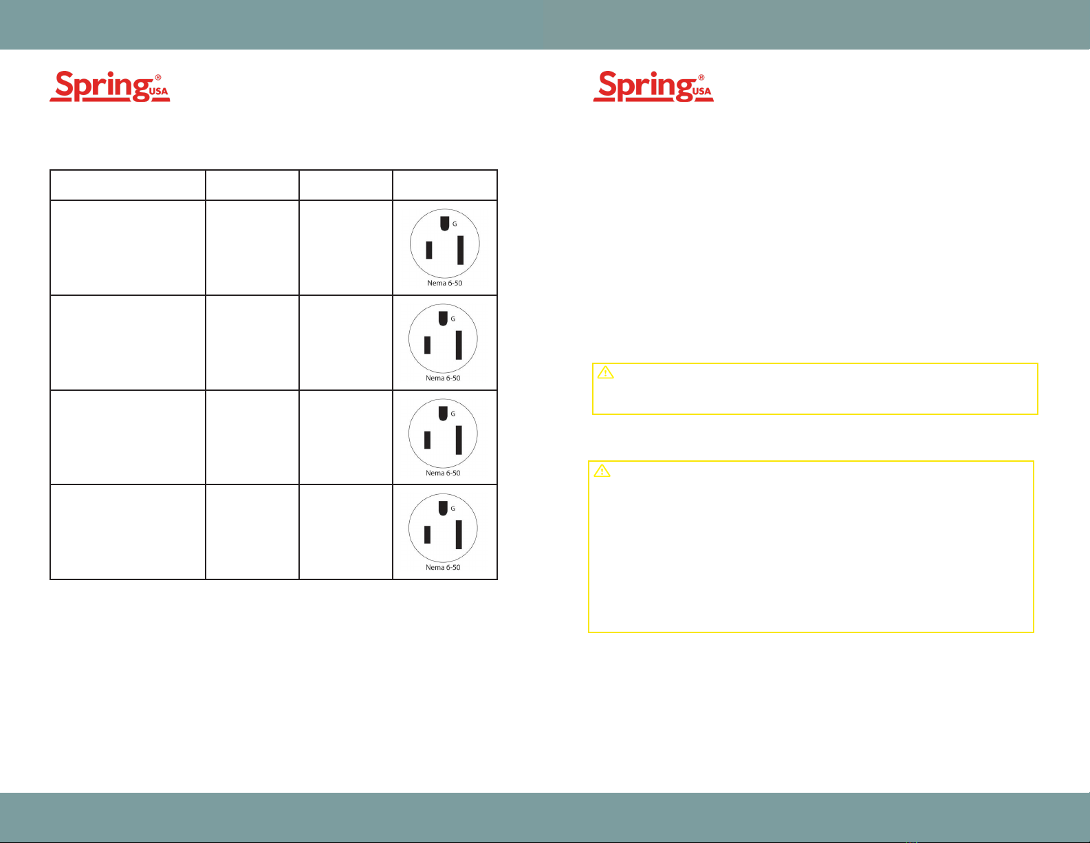
4. This mobile cooking unit is equipped with a NEMA 6-50P plug
before connecting, always make sure the voltage and frequency are
correct and match the nameplate
5. Circuit breakers contain international labels for “On” and “Off “ as
shown below
Features
• Exhibition Style Mobile Cooking
• Heavy Duty Stainless Steel Construction
• MAX Induction System
• Recirculating 4 Stage Downdraft Filtration System
(Grease Baffle Filters, Pre-filter, HEPA, Carbon)
• FLEX - Filter Life Extension Technology
• Safety Interlocks and Filter Detection System
• Integrated Fire Suppression System
• Touchscreen Status Display
• Cutting Board
• Easy to Clean and Maintain
• Energy Efficient
• Low Cost to Operate
• Cooking temperatures up to 450°F and 20 power levels on “Cook”
mode
127 Ambassador Drive, Suite 147 | Naperville, Illinois 60540 | Phone 630.527.8600 | Fax 630.527.8677127 Ambassador Drive, Suite 147 | Naperville, Illinois 60540 | Phone 630.527.8600 | Fax 630.527.8677
I = ON O = O
Installation
Installation, use, and maintenance of this product are to be in
accordance with the Standard for Ventilation Control and Fire Protection
of Commercial Cooking Operations, NFPA 96.
1. Contact your building contractor to arrange fire suppression setup
2. Position the mobile cooking unit on a level floor and lock the casters
in place
3. Confirm HEPA, PRE-FILTER, BAFFLE and CARBON ODOR filters are
properly installed
4. Confirm grease collector drawer and grease pan are installed
5. Confirm all closure panels are properly installed
6. Plug in the mobile cooking unit using the supplied NEMA 6-50P plug
7. Check the status display screen to make sure no fault codes are
present
Do Not Operate the unit without first contacting your building
contractor to arrange setup of the fire suppression system by an
authorized Buckeye Fire Suppression Dealer.
WARNING
Fire Suppression
Always make sure protective bands are installed on the fire suppression
nozzles.
PART NUMBER
MCS59-400 Baffle Filters 2
Pre-Filter 1
HEPA Filter 1
Carbon Order Filter 1
Grease Cup 1
Fire Damper 1
MCS59-401
MCS59-402
MCS59-403
MCS59-333
INQUIRE
MCS59-259 Cutting Board 1
ITEM DESCRIPTION QUANTITY
Included Components Check the pressure gauge on the fire suppression tank on a daily basis.
Refer to the Buckeye Fire Suppression Manual for additional safety,
operating and maintenance instructions.
This Appliance is equipped with a MANUAL PULL STATION that allows
for a manual activation of the fire suppression system.
Manual Activation Instructions (ONLY DO IN A FIRE EMERGENCY)
Pull the ring on the pull station to its full extent to activate the fire
suppression.
Power On Procedure
1. Press the power button on the left column to turn on the filtration
system
2. Check the screen to make sure no error codes or messages are
present
3. Turn the control knob to the desired temperature to power on the
induction appliance; unit is now ready for operation. Temperature
can be adjusted from 90-400°F (32-204°C) for models MCS-59-
FPS-SP251G, MCS-59-FPS-SP261-1, and MCS-59-FPS-SP351WCR-2
and 90-450°F (32-230°C) for model MCS-59-FPS-SP350-2
127 Ambassador Drive, Suite 147 | Naperville, Illinois 60540 | Phone 630.527.8600 | Fax 630.527.8677127 Ambassador Drive, Suite 147 | Naperville, Illinois 60540 | Phone 630.527.8600 | Fax 630.527.8677
MODEL
Included Components
VOLTAGE POWER PLUG
CONFIGURATION
MCS-59-FPS-SP251G 208-240 5000W
10.4 X 2 AMPS
MCS-59-FPS-SP261-2 208-240 5200W
11 AMPS
MCS-59-FPS-SP350-2 208-240 7000W
17 AMPS
MCS-59-FPS-SP351WCR-2 208-240 7000W
15 AMPS
Power Off Procedure
1. Turn the Control knobs on the appliance to the OFF-Position.
NOTE: The filtration system will continue to operate for a period
of 30 Minutes before turning off . DO NOT press the power button
on the column to initiate an abrupt shutdown of the unit. Repeated
abrupt shutdowns may damage the appliances and void warranty.
Once the surface is cool the induction units will go into the stand-by
mode. When in the stand-by mode, the point on the display blinks once
every second.
Avoid touching the glass surface as it may get hot from the heat of
the pan.
CAUTION
The griddle plate is hot when the unit is in use. To avoid burn injuries,
do not touch the surface.
The induction ranges have a very short pre-heat time and can reach
450°F in 4 Minutes. DO NOT leave unattended during operation.
Do not remove or open air closure panels while system is operating.
Do not remove any filters while system is operating, this can cause
the system to shutdown.
CAUTION
Operating Instructions
4. As you turn the control knob the digital display will show the tem-
perature, stop turning the knob when the desired temperature is
displayed

127 Ambassador Drive, Suite 147 | Naperville, Illinois 60540 | Phone 630.527.8600 | Fax 630.527.8677127 Ambassador Drive, Suite 147 | Naperville, Illinois 60540 | Phone 630.527.8600 | Fax 630.527.8677
Figure 1
PART NUMBER
MCS59-400 Baffle Filters Dishwasher Safe, Wash Daily
Pre-Filter Recommended 30 Days
HEPA Filter Recommended 90 Days
Carbon Order Filter Recommended 180 Days
MCS59-401
MCS59-402
MCS59-403
ITEM DESCRIPTION REPLACEMENT SCHEDULE
Filter Installation & Replacement Schedule
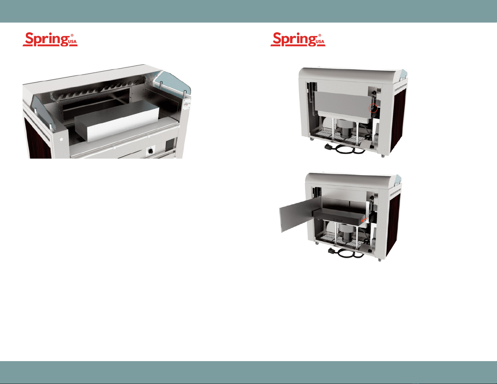
Filter Installation Procedure
Bae Filters
Baffle Filters are re-usable, dishwasher safe, and should be cleaned
daily. Remove the Baffle Filters by pulling up on the filter and sliding the
bottom out as shown below. Only use genuine Spring USA replacement
filters to maintain safe and optimal operation. Use of non-genuine
Spring USA filters will void the warranty. To avoid service disruptions
it is recommended to keep a spare set of filters on hand. Spring USA
assumes no liability for loss of business due to filter related shutdown.
• Do not place empty cookware on the cooking zone, empty pans and
pots can heat up very quickly. Instead, place grease or liquid into the
pan prior to placing the pan on the cooking surface.
• If using oil or grease during the cooking process, constantly check
the pan to make sure the contents don’t overheat and burn.
• Keep the pan in the center of the heating area.
• Do not place any flammable objects such as cardboard between the
pan and the heating area as this may cause a fire.
• Do not leave pans unattended.
• Do not place any metallic objects such as jewelry, closed cans,
aluminum foil, cutlery, watches etc. on the heating surface of the
induction appliance. Metallic objects heat up very quickly when
placed on the induction cooktop.
• Avoid placing any objects sensitive to magnetism on the glass
cooking surface.
• Do not let any liquid overflow the pan onto the cooker surface.
• If the heating surface is damaged (cracked or broken) discontinue
use and contact Spring USA. Do not touch any parts inside the
appliance.
• Do not operate in ambient temperature of more than 100°F, doing
so can cause overheating and shutdown of the appliance.
• Always make sure the unit is OFF when not actively cooking on the
appliance.
Griddle Instructions:
• Always season the griddle surface before placing any protein on it.
• If cooking frozen food avoid using the same positions on the griddle.
Otherwise the surface could deform locally overtime.
Operating Instructions
Before operating the unit ensure all objects are removed from the
induction surface and the grease pan, grease collector, and filters
are installed properly.
NOTICE
127 Ambassador Drive, Suite 147 | Naperville, Illinois 60540 | Phone 630.527.8600 | Fax 630.527.8677127 Ambassador Drive, Suite 147 | Naperville, Illinois 60540 | Phone 630.527.8600 | Fax 630.527.8677
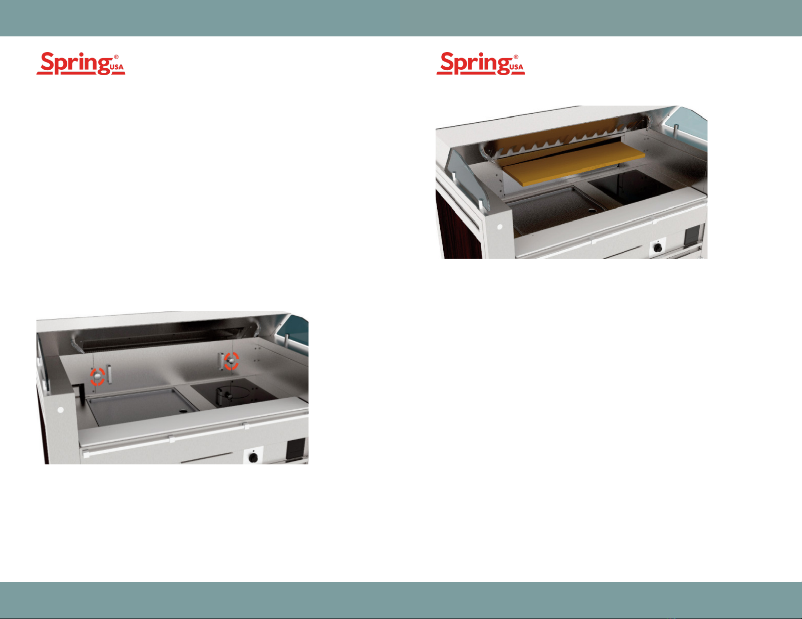
Pre-Filter Replacement Procedure
Pre-Filter
The Pre-Filter (Part No. MCS59-401) is a low cost disposable hi-temp
filter. Do not operate the appliance without the pre-filter, doing so will
shorten the life of the HEPA filter. Do not attempt to clean the Pre-Filter,
replace in 30 days or sooner.
1. Remove the Baffle Filters as shown (Figure 1)
2. Remove the Filter Access Panel as shown below by removing the
panel knobs
3. Slide the bottom of the access panel towards you and then lift up to
remove the panel
4. Install the Pre-Filter in the correct orientation (air-flow arrow
pointing down)
5. Install the filter access panel
6. Install the access panel knobs and tighten. To avoid stripping the
thread, do not over-tighten
7. Replace the baffle filters
Figure 2
Figure 3
HEPA Filter Replacement Procedure
HEPA Filter
HEPA Filter (Part No. MCS59-402) is a disposable filter that should be
replaced every 6 months or sooner.
1. Remove the Baffle Filters (Figure 1)
2. Remove the Filter Access Panel
3. Remove the Pre-Filter (Figure 3)
4. Remove the HEPA filter by lifting it up and sliding it out of the
duct work (Figure 4)
5. Replace the HEPA Filter in the correct orientation (Gasket side
down and air-flow arrow pointing down)
6. Place the Pre-Filter on top of the HEPA
7. Install front access panel and tighten the knobs
8. Reinstall the Baffle Filters
127 Ambassador Drive, Suite 147 | Naperville, Illinois 60540 | Phone 630.527.8600 | Fax 630.527.8677127 Ambassador Drive, Suite 147 | Naperville, Illinois 60540 | Phone 630.527.8600 | Fax 630.527.8677
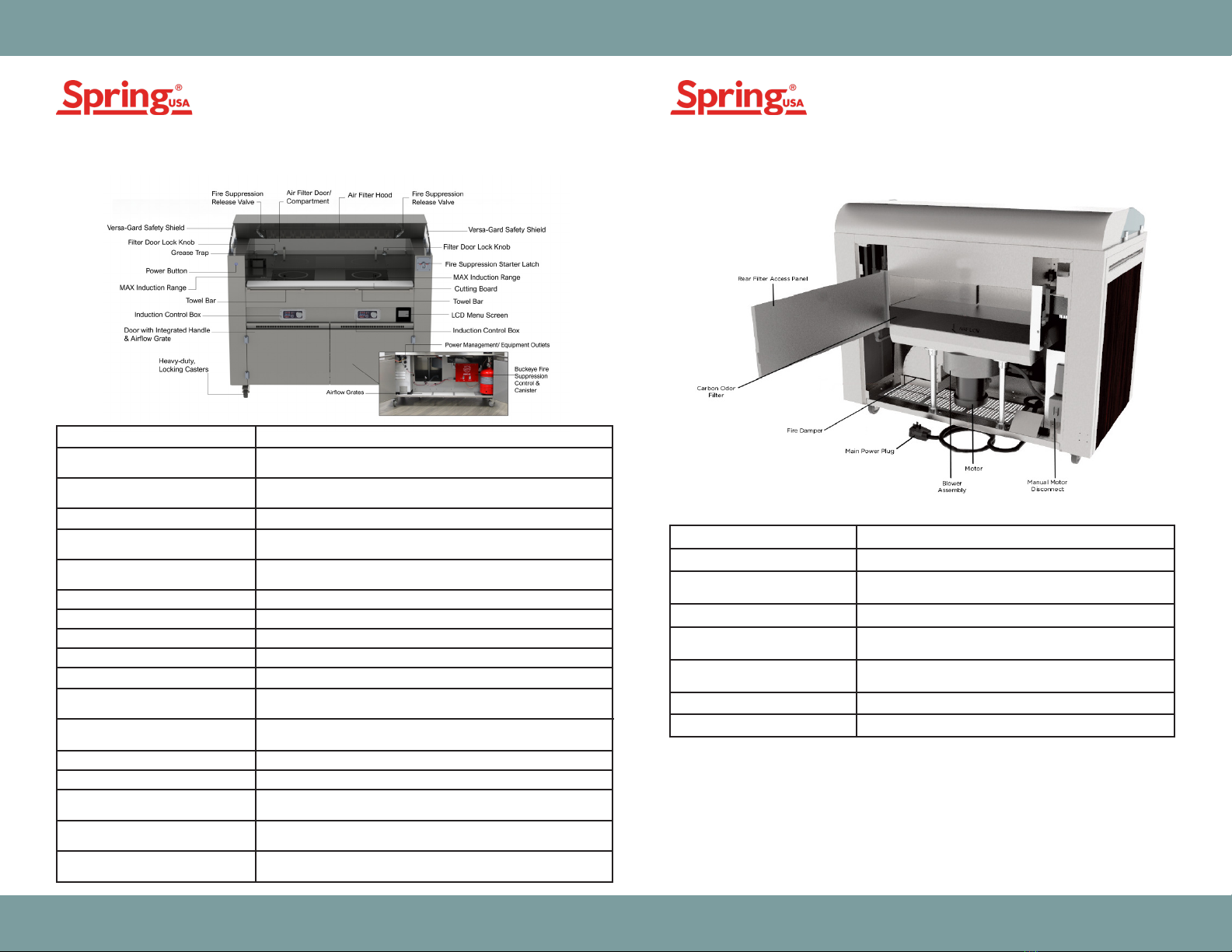
Carbon Odor Filter
Carbon Odor Filter (Part No. MCS59-403) is a disposable odor filter that
should be replaced every 6 months or sooner.
1. Remove the back panel by lifting up on it
2. Open the rear access panel shown below
3. Remove the carbon Odor Filter
4. Replace the Carbon Odor Filter in the correct orientation (air-flow
arrow pointing down)
5. Close and latch the rear filter access panel and install the back
access panel
Figure 4
Figure 5
Figure 6

127 Ambassador Drive, Suite 147 | Naperville, Illinois 60540 | Phone 630.527.8600 | Fax 630.527.8677127 Ambassador Drive, Suite 147 | Naperville, Illinois 60540 | Phone 630.527.8600 | Fax 630.527.8677
Cleaning Instructions
Turn off the appliances by placing the controls in the OFF position. Make
sure the 30min timer expired and the filtration system is shutdown.
Allow the appliances to cool before proceeding.
1. Remove the BAFFLE FILTERS, GREASE CUP, CUTTING BOARD, and
GREASE COLLECTION DRAWER.
2. Clean the BAFFLE FILTERS, GREASE CUP, CUTTING BOARD, and
GREASE COLLECTION DRAWER in a sink or dishwasher using mild
detergent and warm water.
3. Remove the Filter access panel and using a clean moistened cloth
with warm water and mild detergent wipe the inside of the grease
drain channel.
4. Wipe the countertop, filter access panel and surrounding areas with
a clean moistened cloth with warm water and mild detergent. Rinse
by wiping with a clean cloth moistened with warm water.
5. Dry the removed components with a clean non-abrasive cloth.
6. Reinstall the removed components.
1. Open the front doors and remove the appliance AIR INTAKE
FILTERS shown below by pressing up on its corners.
2. Clean the AIR INTAKE FILTERS in a dishwasher. Wipe the Filters DRY
before inserting them back into the filter holders.
DAILY OR AS NEEDED CLEANING INSTRUCTIONS
WEEKLY CLEANING INSTRUCTIONS
1. Clean the mobile cooking unit and appliances by following the Daily
Cleaning Instructions.
2. Remove the BAFFLE FILTERS AND THE FRONT FILTER ACCESS
PANEL in this order.
3. Remove the PRE-FILTER and the HEPA FILTER.
4. Wipe the inside of the of the duct work surrounding areas with a
clean moistened cloth with warm water and mild detergent. DO NOT
spray water or any other liquid inside the duct work. Do not grab
onto the fusible links or the cable supporting them.
5. Reinstall the HEPA, PRE-FILTER, FRONT FILTER ACCESS PANEL
and BAFFLE FILTERS in this order.
6. Remove the back panel.
7. Open the rear Filter access panel. Remove the CARBON ODOR
FILTER.
8. Wipe the inside of the of the duct work surrounding areas with a
clean moistened cloth with warm water and mild detergent. DO NOT
spray water or any other liquid inside the duct work. Rinse by wiping
with a clean cloth moistened with warm water.
9. Reinstall the Carbon Odor Filter, close the rear filter access panel
and replace the back panel.
MONTHLY CLEANING INSTRUCTIONS
Cleaning the Countertop and Surrounding Areas:
Allow Unit to cool and shutoff before cleaning.
CAUTION
Ensure no liquid can enter into the induction unit. Do not let water or
food overflow the cooking area. Do not use hoses to clean or power
wash the induction unit or its vicinity. Clean the mobile cooking station
by wiping only.
CAUTION
Cleaning the griddle plate can produce hot steam. DANGER OF
BURN INJURIES.
CAUTION
Do not use strong detergents or dissolvers such as Ketone, Ester,
and alkaline detergents to clean the griddle surface as they may
damage the surface
CAUTION
127 Ambassador Drive, Suite 147 | Naperville, Illinois 60540 | Phone 630.527.8600 | Fax 630.527.8677127 Ambassador Drive, Suite 147 | Naperville, Illinois 60540 | Phone 630.527.8600 | Fax 630.527.8677
Heavy-duty, Locking Casters 5" casters are more durable & easier to push than industry-
standard 4" casters
Induction Control Box Use to turn on/off induction range and set cooking temperature
Towel Bar Can be used as a towel bar, utensil holder, or a handle to help
operator pull the cart out to access the back panel
MAX Induction Range More even heat distribution and precise temperature control
for a more efficient solution over traditional gas or electric
Power Button Use to turn cart on/off
Grease Trap Part No: MCS59-333 Dishwasher Safe, remove and wash daily
Versa-Gard Food Shield NSF-compliant food shields
Fire Suppression Release Valve Always make sure protective bands are installed on the nozzles
Air Filter Door / Compartment Remove to access HEPA and Pre-Filter. Must be in place for
unit to operate
Air Filter Hood Part No: MCS59-400 Baffle Filters, Dishwasher safe, remove
and wash daily
Cutting Board Part No: MCS59-259
LCD Screen Displays appliance status and error codes
Power Management / Equipment
Outlets
Power source for induction ranges
Buckeye Fire Suppression
Control & Canister
Do Not Open. Service to be performed by qualified personnel
Airflow Grates Grates that release air that has been filtered through the
4-stage air filtration system
Filter Door Lock Knob Part No: MCS59-304
Door with Integrated Handle &
Airflow Grate
Vents that release air after it has run through the 4-stage
filtration system
DESCRIPTION DETAILS
Rear Filter Access Panel Must be closed for unit to operate
Fire Damper Part No. INQUIRE. Replace annually
Main Power Plug NEMA 6-50P power plug. Disconnect before
performing service
Blower Assembly Do not place any foreign objects in the duct work that
may obstruct the blower
Motor 1 HP TEFC 56C Frame 3Phase Motor
Manual Motor Disconnect Use only in emergency to disconnect power to motor
Carbon Odor Filter Part No. MCS59-403. Recommended replacment
interval 6 months or sooner
DESCRIPTION DETAILS
Appliance Front View Appliance Rear View

127 Ambassador Drive, Suite 147 | Naperville, Illinois 60540 | Phone 630.527.8600 | Fax 630.527.8677127 Ambassador Drive, Suite 147 | Naperville, Illinois 60540 | Phone 630.527.8600 | Fax 630.527.8677
Baffle Filter Missing Missing filters or duct
air pressure ports
blocked
Install missing filters. Check air pressure
ports inside of the duct for any
obstruction. If necessary, disconnect
the air line via push-to-fitting to clear
blockage. Reinstall the air line making
sure it’s fully seated within the fitting.
HEPA or Pre-Filter
Missing
Missing filters or duct
air pressure ports
blocked
Install missing filters. Check air pressure
ports inside the hood for obstruction.
If necessary, disconnect the air line
via push-to-fitting to clear blockage.
Reinstall the air line making sure it’s fully
seated within the fitting.
Carbon Filter
Missing
Missing filters or duct
air pressure ports
blocked.
Install missing filters. Check air pressure
ports inside the hood for obstruction.
If necessary, disconnect the air line
via push-to-fitting to clear blockage.
Reinstall the air line making sure it’s fully
seated within the fitting.
Front Filter Access
Panel Open
Panel missing or not
installed properly
Check front filter access panel to make
sure it’s installed properly.
Rear Filter Access
Panel Open
Rear filter access
panel not closed
Confirm rear filter access panel is closed
and latched properly.
Motor Overload Blower intake
blockage
Inspect and replace dirt filters.
CPU Battery Low Bad Battery Contact Spring USA for replacement.
Fire Suppression
Not Ready
Fire suppression not
set up
Contact Spring USA or Buckeye
Authorized Dealer to inspect and charge
system. DO NOT tamper with the fire
suppression system.
FAULT CODE POSSIBLE CAUSES SUGGESTED ACTION
Cooking appliances
do not power on
• Confirm all filters are installed
• Confirm all closure panels are installed properly
• Confirm ventilation is on
• Check for fault codes on the status display screen
• Confirm cooking appliances are plugged in at the provided
receptacles only
• Disconnect main power and confirm circuit breakers are not
tripped
Ventilation does not
turn on
• Confirm fire suppression is charged and in ready state
• Confirm all closure panels are closed
• Check blower for any obstruction inside the duct work
• Disconnect main power and confirm circuit breakers are not
tripped
Ventilation does not
turn off
Confirm cooking appliances are in the off position.
Ventilation noise
has increased
significantly
Replace filters
Cooking appliance
power is reduced
• Confirm that cooking appliance air intake filters are clean
• Confirm that ambient temperature is below 100°F
ISSUE SUGGESTED ACTION
Troubleshooting Guide - Status Display Codes Troubleshooting Guide
Required Maintenance
1. Part # MCS59-400 Baffle Grease Filters Dishwasher Safe Wash Daily
1. Replace part # MCS59-401 Disposable 1 Pre-Filter
2. Clean induction cook-top intake filters (if supplied – model specific)
3. Inspect all filters for damage - replace if damaged
4. Confirm Fire damper is installed properly
5. Inspect duct work for any grease build-up within the duct work
- Clean by wiping with a damp cloth and gleaning agent. Do Not
Wash Down With Pressure
6. Inspect cook-top joints for silicon adhesive integrity – re-apply
food grade silicon if necessary. Always confirm that no liquid is
penetrating below cooktops
7. Inspect casters are not damaged and when locked successfully
prevent appliance movement. Replace if necessary
Maintenance Schedule
Daily Or After Each Use:
Monthly:

127 Ambassador Drive, Suite 147 | Naperville, Illinois 60540 | Phone 630.527.8600 | Fax 630.527.8677127 Ambassador Drive, Suite 147 | Naperville, Illinois 60540 | Phone 630.527.8600 | Fax 630.527.8677
8. Verify that the extinguishing system is in its proper location
9. Verify that the manual actuators are unobstructed
10. Verify that the tamper indicators and seals are intact
11. Verify that the maintenance tag or certificate is up to date and in place
12. Verify that no obvious physical damage or condition exists that might
prevent operation
13. Verify that the extinguishing system pressure gauge is in the operable
range
14. Verify that the nozzle blow off caps are intact and undamaged
15. Verify that the hood, duct, electrical controls, safety interlocks and
cooking appliances have not been replaced, modified, or relocated
1. Replace HEPA filter part # MCS59-402
2. Re-place carbon filter Part # MCS59-403
1. Inspect pneumatic tubing for damage and grease buildup – replace
or clean if needed
2. Clean pitot tube, pneumatic fittings and ports
1. Replace Fire Damper
1. Check and inspect the system in accordance with steps 1 – 7 of
semi-annual maintenance instructions
2. Disconnect the Systems Releasing Module from the cylinder valve
by removing the four screws securing the SRM to the top of the
valve and separate. DO NOT lose or damage the Interface Gasket
because it will be required to reconnect the SRM. If the SRM is
mounted remotely, remove all Model BFR-CAP(s), Valve Cap
Assembly from each of the cylinder valve(s) by unscrewing the
four mounting screws and remove them from the cylinder valve(s).
1. Check that the hazard area 1 has not changed.
2. Check the cylinder pressure gauge, making sure it is in the operable
range.
3. Check all nozzle orifices to assure that they are unobstructed and
that all nozzle caps are in place
4. If any BFR-UBC stainless steel metal caps are used, they must be
removed, cleaned and checked to assure that they slide easily on
and off the nozzle body. If the cap does not slide easily off the
nozzle tip, the o-ring and cap must be replaced.
5. Remove the face plate from the control head
6. Remove the actuation nitrogen cartridge from the systems releasing
module. If the use of the Keeper pin is desired to prevent the
operation of the gas valve and miniature electric
7. Check entire system for mechanical damage
8. Inspect fusible link detection line for grease build-up or mechanical
damage. Replace corner pulleys or conduit, if necessary.
Quarterly:
Semi-annually:
Annually:
Semi-annual maintenance of the Kitchen Mister System
Is required by NFPA-17A and Buckeye Fire Equipment
And must be performed by a factory trained, Authorized
Buckeye Fire Equipment Dealer. Semi-annual
Maintenance shall include the following:
Annual maintenance of the Kitchen Mister System
Is required by NFPA-17A and Buckeye Fire Equipment
And must be performed by a factory trained, Authorized
Buckeye Fire Equipment Dealer. Annual
Maintenance shall include the following:
9. Activate the Systems Releasing Module by releasing tension from
the end of the fusible link line by cutting or melting the last link.
Make certain that the Systems Releasing Module fires, the gas
valve closes, and all auxiliary devices connected to the micro-
switch operate or stop
10. Replace all fusible link detectors
11. Reset the Systems Releasing Module and then activate the system
by using the remote pull station. Make certain that the Systems
Releasing Module fires, the gas valve closes, and all auxiliary
devices connected to the micro-switch operate or stop
12. After the SRM has been tested and is functioning properly, the
system can be put back into service
13. If a Keeper Pin was used, remove it from the Systems Releasing
Module
14. Before installing the Nitrogen Cartridge, it is necessary to make
sure that the Actuating Pin is moving freely. Insert the Actuation
Pin Resetting Tool into the threaded hole of the Manifold Mounting
Block where the Nitrogen Cartridge is installed and then remove
the BFR-PRT
15. Install the Nitrogen Actuation Cartridge by completely screwing
the cartridge into the manifold block
16. Re-install the Systems Releasing Module cover
17. Verify that the date on the cartridge is visible in the viewing
window

127 Ambassador Drive, Suite 147 | Naperville, Illinois 60540 | Phone 630.527.8600 | Fax 630.527.8677127 Ambassador Drive, Suite 147 | Naperville, Illinois 60540 | Phone 630.527.8600 | Fax 630.527.8677
Contact an Authorized Spring USA Distributor
immediately If any deficiencies are found.
Note: A record of monthly inspections is to be kept by the
owner of the system that includes the date of inspection,
the person performing the inspection, and any corrective
action required.
3. Reinstall the Nitrogen Activation Cartridge. To check the
satisfactory operation of the fusible link system, cut the terminal
link or the “S” Hook attached to the terminal link. This will release
tension on the fusible link line causing the following to occur:
1. 1 The Systems Releasing Module will operate, causing
the detection arm assembly to move back to the left,
disengaging the trigger, and allowing the actuation lever
to operate. The actuation pin will puncture the nitrogen
cartridge and allow the nitrogen gas to discharge through
the bottom of the SRM or BFR-CAP(s)
2. The pressurization indicator of each Test Valve Assembly
(when used) will be fully extended and there are no leaks in
the copper tubing
3. The gas valve will close, stopping gas flow to any gas fueled
appliances
4. All auxiliary devices connected to the miniature electrical
switch(s) provided in the Systems Releasing Module will
have operated
1. The Systems Releasing Module will operate, causing
the detection arm assembly to move back to the left,
disengaging the trigger, and allowing the actuation lever to
operate
2. All auxiliary devices connected to the miniature electrical
switch(es) provided in the Systems Releasing Module will
have operated
4. Remove the used nitrogen cartridge and discard immediately
5. Replace all fusible link detectors
6. After testing the fusible link line, repair the terminal link and re-set
the control head
7. Once the Systems Releasing Module is reset, the mechanical pull
station must be checked. To do so, pull the handle on the remote
pull station and make sure that the following occurs:
8. Disconnect the discharge piping from the cylinder valve. Using
air or nitrogen, blow out the discharge piping and make sure all
the nozzle caps have blown off. If any nozzle cap(s) fails toblow
off during test, carefully examine piping system and nozzle(s) to
determine cause and take appropriate corrective action. Repeat
test to assure both piping system and nozzles are unobstructed.
9. Reconnect the discharge piping to the cylinder valve and check
that all nozzle caps are installed properly
10. Reconnect the Systems Releasing Module or Valve Cap Assembly(s)
to the appropriatecylinder valve(s) and secure each with the four
provided screws.
11. Before installing the Nitrogen Cartridge it is necessary to make
sure that the Actuating Pin is moving freely. Insert the Actuation
Pin Resetting Tool into the threaded hole of the Manifold Mounting
Block where the Nitrogen Cartridge is installed.
12. Install a new Nitrogen Actuation Cartridge by completely screwing
the cartridge into the manifold block.
13. Write the current date on the gray band of a new Nitrogen Actuation
Cartridge so that it can be seen in the viewing window of the SRM.
14. Re-install the Systems Releasing Module cover. Verify that the date
on the cartridge is visible in the viewing window.
1. In addition to the required annual maintenance, all agent cylinders
must 1 be removed from the system, discharged, and hydrostatically
tested as per the requirements of NFPA-17A. The cylinder should
then be recharged in accordance with Buckeye Kitchen Mister
manual and returned to service. Note: New extinguishing agent must
be used when performing this procedure.
2. Replace motor input shaft seal.
12 Year Maintenance:
127 Ambassador Drive, Suite 147 | Naperville, Illinois 60540 | Phone 630.527.8600 | Fax 630.527.8677127 Ambassador Drive, Suite 147 | Naperville, Illinois 60540 | Phone 630.527.8600 | Fax 630.527.8677
Required Maintenance OWNER’S MONTHLY INSPECTION LOG
PERFORMED BYFREQUENCYDESCRIPTION
Owner/UserMonthlyFire Suppression System Inspection per
manufacturer’s recommendations
Owner/UserAs Needed
Change Filter
Owner/UserAs Needed
Clean Mobile Cooking Unit following
Daily/Weekly and Monthly Instructions
Authorized Buckeye
Dealer
Semi-AnnualPerform semi-annual maintenance
of the fire suppression system as
described in the Buckeye Kitchen Mister
System Manual Chapter 5 (System
Inspection and Maintenance)
Authorized Buckeye
Dealer
Semi-AnnualPerform inspection and testing of
safety interlocks and fire damper
Authorized Buckeye
Dealer
Semi-Annual
Replace fusible links
Authorized Buckeye
Dealer
AnnualPerform annual maintenance of
suppression system as described in the
Buckeye Kitchen Mister System
Manual Chapter 5 (System Inspection
and Maintenance)
Authorized Buckeye
Dealer
AnnualReplace the fire damper Part No.
32000024
It’s the Owner’s responsibility to conduct a monthly inspection of the fire suppression system in
accordance to manufacturer’s operation manual including the items listed in the inspection log.
Verify the extinguishing system
is in its proper location.
The manual actuators are
unobstructed.
The tamper indicators and
seals are intacr.
The maintenance tag or
certificate is up to date and
in place
No obvious physical damage
or condition exists that might
prevent operation.
The pressure guage is in the
operable range.
The nozzle blow off caps are
intact and undamaged
The hood, duct, and cooking
appliances have not been
replaced, modified, or
relocated.
The maintenance log is in place
and up to date.
ITEMS TO VERIFY NAME/
DAT E
NAME/
DAT E
NAME/
DAT E
NAME/
DAT E
NAME/
DAT E
NAME/
DAT E
NAME/
DAT E
NAME/
DAT E
NAME/
DAT E
NAME/
DAT E
NAME/
DAT E
NAME/
DAT E
127 Ambassador Drive, Suite 147 | Naperville, Illinois 60540 | Phone 630.527.8600 | Fax 630.527.8677127 Ambassador Drive, Suite 147 | Naperville, Illinois 60540 | Phone 630.527.8600 | Fax 630.527.8677
MAX Induction
Before You Begin:
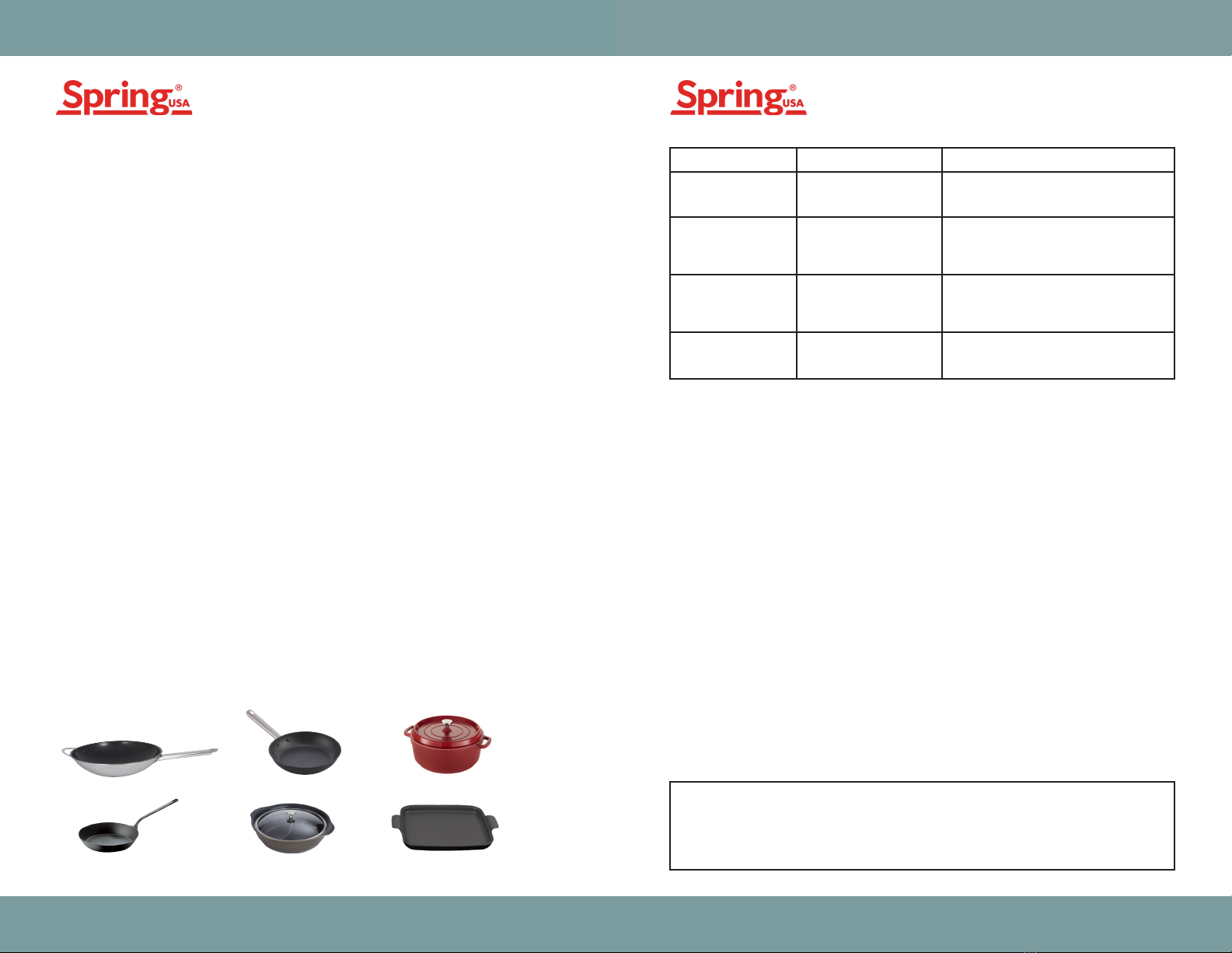
Suitable Serving Ware:
Safety Precautions & Key Points:
Read the following instructions in their entirety. Use proper serving
vessels. All serving vessels must be induction-ready.
Your MAX Induction®Range must have proper ventilation in order to
operate correctly. There must be at least 7" of space available under
a mounted induction range. Cabinets housing the induction range (s)
should have intake & exhaust vents. Active ventilation may be needed.
For optimal performance, the inside temperature of the cabinet should
not exceed 90°F / 32° C.
Ensure that you have dedicated power to the installed location. Refer to
the grid on Page 6 for Electrical Specifications.
Cabinet Ventilation must be provided. The inside temperature of the
cabinet must not exceed 90°F / 32° C. Regularly inspect air intake grill
on underside of ranges. Clean by vacuuming, as needed. Ventilation
areas into and out of the cabinet should be provided. Active ventilation
may be necessary dependent on cabinet design. Attach Control Panel to
range prior to connecting to power source.
Actual range temperatures may vary due to a number of variables such
as ambient temperature in the immediate surrounding area, content and
volume of food being heated or cooked, and whether or not you are
utilizing a cover on the vessel you are using.
Never attempt to service any part of your MAX Induction®Range on
your own. Contact our Service Department by calling (1) 630-527-8600.
Attempting to service your Induction Range on your own, or through
an unauthorized repair facility automatically voids your warranty. For
service forms, visit the Spring USA Website. Always disconnect from
power source prior to removing range from cabinet.
For Limited Warranty Information, visit www.springusa.com/warranty
Your MAX Induction®Range works with induction-ready serving vessels.
Visit the Spring USA Website for a full line of induction-ready,
professional serve ware.
Serving pieces must have a flat bottom, in order to make full contact
with the countertop.
Serving pieces that are footed, or that have a raised ridge, are not for
use on this system, as they cannot make full contact with the counter
surface.
Vessels must have a bottom diameter greater than 4".
Glass Cookware is not suited for use on your induction warming system.
Serving vessels must be centered on the induction warmer for optimal
heating and performance.
Non-Stick Wok Aluminum Fry Pan
Aluminum Cookware with
Induction Disc
Cast Iron
IronLite Cookware
Carbon Steel
E0 Range does not
detect a pan on the
range.
Place an induction ready pan on the
range.
E1 Range has overheated
due to blocked
ventilation and has
shut down the range.
Clear vents, let range cool down, then
restart. If error message continues, your
range needs to be serviced.
E2 Overheating
protection has been
activated & the range
has been shut down.
Remove the cookware from the range.
Let the unit cool down, then restart.
Make sure the cookware you are using is
induction ready.
E3 Range is experiencing
temporary voltage
overload.
Let the induction range cool down
completely, before restarting. Review
dedicated power requirements.
ERROR CAUSES SOLUTION
This equipment uses, generates and can radiate radio frequency
energy. If not installed correctly and used in accordance with
the instructions, may cause harmful interference to radio
communications.
NOTICE

127 Ambassador Drive, Suite 147 | Naperville, Illinois 60540 | Phone 630.527.8600 | Fax 630.527.8677127 Ambassador Drive, Suite 147 | Naperville, Illinois 60540 | Phone 630.527.8600 | Fax 630.527.8677
Mounting Control Panel
How To Operate
To mount the Control Panel (B), use the template provided. Place the
template on a plane or panel, perpendicular to the MAX Induction®
Range, centering it to the range whenever possible.
The Control Panel cutout should measure 53/4"x 23/4 ”. Place the Control
Panel (B) into cutout hole. Using the four (C) wood screws provided,
secure the Control Panel into place.
Using Your MAX Induction®Range:
Attach Control Panel to range prior to connecting to power source. Turn
the induction range on (remember, the induction unit, by default, will
start out in cook mode). An ‘E0’ message will appear in the panel. Place
an induction-ready pan or server on the induction range. The display will
begin to read the set temperature.
Set a stainless steel pan or server filled with water on top of the granite
directly over the induction range mounted underneath. The blinking LED
light should go solid. This means the induction range is reading the pan.
Your MAX Induction®Range is designed to operate in two modes:
“Cook” or “Temp”.
“Cook” Mode offers you high-speed heating, used for sautéing, omelet
stations, pasta bars or demonstration cooking.
In “Cook” Mode:
• An ‘E0’ code will flash until suitable cookware is placed on the glass
surface of the range
• The LED panel will display a two-digit number indicating the power
level. Power levels run from 1 thru 20
• As a safety precaution, if no cookware is placed on the induction
range plate after 2-1/2 minutes, the unit will shut off
• Once suitable cookware has been placed on the glass induction
plate, the unit will continue to cook until the range is manually shut
down, or the mode is changed over to “Temp” mode
Note: There must be at least 7” of space available under a mounted
induction range. Cabinets housing the induction ranges should have
both vents & circulation fans installed. The inside temperature of the
cabinet must not exceed 90°F / 32° C.
In “Temp” Mode:
• An ‘E0’ code will flash until suitable cookware is placed on the glass
surface of the range
• The LED panel will display a three-digit number indicating the
temperature setting. To increase the temperature setting, turn the
dial clockwise To decrease the setting, turn the dial to the counter-
clockwise.
• The induction range will continue to warm the food until the set
temperature has been reached. Once the temperature has been
reached, the range will maintain that pre-selected temperature
setting.
• Temperature settings in “Temp” mode, in fahrenheit are: 110°, 120°,
130°, 140°, 150°, 160°, 170°, 180°, 190°, 200°, 220°, 240°, 260°, 280°,
300°, 320°, 340°, 380° & 400°
Celsius: 43°, 49°, 54°, 60°, 66°, 71°, 77°, 82°, 88°, 93°, 104°, 116°, 127°,
138°, 149°, 160°, 171°, 182°, 193° & 204°.
MODEL # VOLTAGE/AMPS PEAK POWER PLUG TYPE
SM-351WCR 208-220 Volts
14.6 Amps 3500 Watts 50-60 Hz NEMA 6-20 6" Cord
SM-261R 208-220 Volts
11.8 Amps 2600 Watts 50-60 Hz NEMA 6-20 6" Cord
SM-350R 208-220 Volts
14.6 Amps 3500 Watts 50-60 Hz NEMA 6-20 6" Cord
SM-251-2CR 208-220 Volts
10.4 x 2 Amps 2500 X 2 Watts 50-60 Hz NEMA 6-30P
“Temp” Mode offers you thermostatically controlled holding
temperatures for use with soups, sauces, buffets or pastry work. The
LED display allows for more accurate temperature selection.

127 Ambassador Drive, Suite 147
Naperville, IL 60540-4079
P: 630-527-8600
F: 630-527-8677
www.springusa.com
This manual suits for next models
3
Table of contents
Other Spring USA Cooker manuals


Popular Cooker manuals by other brands

Ninja
Ninja Foodi MC1001UK instructions

SKLADOVA TEHNIKA
SKLADOVA TEHNIKA Plamak instruction manual

Bosch
Bosch HGA120B29S User manual and installation instructions

Proline
Proline EFG 502 user manual

Electrolux
Electrolux EKE 5101 Instruction book

Siemens
Siemens HQ738155E Instructions for installation and use

Modena
Modena Giusto Series User manual book

Falcon
Falcon Professional+ FX 100 Dual Fuel User's guide & installation instructions

Kenwood
Kenwood CK 304 G Instructions for use

Indesit
Indesit K3E11/R Instructions for installation and use

ROBAND
ROBAND DIPO DCR23 operating instructions

Gorenje
Gorenje GM 145 manual


