Spring Well CF+ Operating and safety instructions

CF+ System
Setup And Installation
Questions? Call (800)-589-5592 1

Setup And Installation
System Contents
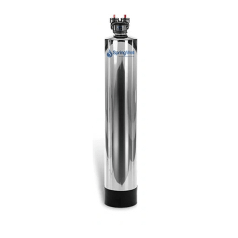
Carbon Filter
Tank (CF+)
Pre-Filter
Gasket and Lube
Spanner
Wrench
Sediment
Filter
Mounting
Bracket
Recommended Supplies
Primer and Cement
1.5-inch Tee
Connector (Slip) (x2)
1 Roll Plumbers
Tape
1.5-inch PVC Pipe (10’ used in this
manual)
1.5-Inch PVC Shut Off
Valves (x3)
System Configuration
Water Source
From Outside Home Filtered and Softened
Water Into Home
(1) Water from your
source will begin by
entering the Pre-Filter
(2) The Carbon Filter
Filter (CF+) will be the
second tank and will
remove chemicals such
as chlorine
1
2
Hose Bib
Assembly (2)
1.5-inch Elbow
Connector (Slip) (x8*) 1.5-inch Adapter (Slip
x Thread) (x4)
CF+ System
Questions? Call (800)-589-5592 2
* The quantities are suggestions. Your system configuration may vary depending on installation area.

Leaning Tank
PLEASE READ INSTRUCTIONS FULLY PRIOR TO ATTEMPTING INSTALLATION. Be sure to follow
all applicable plumbing codes. The system must be installed on a main water supply line
Caution: Do not install on well water unless you have spoken to a customer service
representative first.
CF+
Tank Width 13”
Tank Height 54” (58” with Head)
Flow Rate 20 GPM Service
Connection Size 1.5”
Operating Pressure 25-80 PSI
Operating
Temperatures
36 –120 F
Pre-Filter
Change/Replacement
Every 6-9 Months
Media
Change/Replacement
Every 10 years or 1
Million Gallons
Product Specs
Tank Boot
Level Tanks
If the tank is not perfectly straight, carefully lift the tank straight up a few inches and tap it on the ground until
the tank stands vertically and fits snuggly into the tank boot.
Questions? Call (800)-589-5592 3
CF+ System

IMPORTANT! The carbon media inside the filter system MUST soak in water for a minimum of
48 hours prior to installation
Carbon Soak Instructions (48 Hours Prior)
Carbon Filter
Tank (CF+)
Hose Bib
Assembly (x2)
Lawn Hoses (x2) and
access to a faucet
This step will require the materials listed below
2) Due to weight, stage the tank
near the installation area. The
two connectors will allow you to
route 1 hose to the tank and 1
hose away from the tank.
3) Connect the hose from the
faucet into the Inlet on the tank.
Connect the open hose to the
outlet and lead away from your
work area.
4) Run the faucet until you see
water exiting the other hose.
5) Disconnect the Hose Bib
adapters from the Carbon Filter
Tank
6) Set the tank aside and
allow it to sit for 48 hours.
1) Thread a Hose Bib into the
inlet and outlet of the Carbon
Filter Tank (CF+)
Questions? Call (800)-589-5592 4
CF+ System

IMPORTANT! The carbon media must be flushed on both tanks prior to install
Carbon Flush Instructions
This step will require the materials listed below
7) This step can only be
performed after the tank has
been soaked for 48 hours.
8) Attach the Hose Bib
Assembly onto the inlet and
outlet ports.
9) Attach the hoses to the tank.
The hose leading to the inlet will
be connected to a faucet. The
outlet hose will allow the water
to drain.
10) Run the hose and allow the
water to flush out the tank until
the water runs clear.
11) Switch the hoses to now
run the water through the
outlet. Allow the water to
flow in the opposite
direction until it runs clear.
12) Remove the hose bib
assemblies from the Carbon
Filter tank.
Carbon Filter
Tank (CF+)
Hose Bib
Assembly (x2)
Lawn Hoses (x2) and
access to a faucet
Questions? Call (800)-589-5592 5
CF+ System

Assembling a Bypass Valve
Bypass Operation
13) Prior to working with the
pre-plum you must ensure the
water to the main has been shut
off.
14) Prep the pre-plumb and
identify the water flow
direction.
15) To keep the bypass accessible
it is recommended to work it
upwards. Start by connecting an
elbow to each connection
pointing them upwards.
Note: The tank does not have a built-
in bypass valve. Therefore you will
need to build a bypass to allow for
easy system maintenance. Bypass on. No water flow to
system
Bypass off. Water flows
through system
Recommended Supplies
Primer and Cement
1.5-inch Tee
Connector (Slip) (x2)
1.5-inch PVC Pipe (Cut to fit)
1.5-inch Elbow
Connector (Slip) (x4*)
1.5-Inch PVC Shut Off
Valves (x3)
IMPORTANT: The system will be
under pressure so all slip connections
must be primed (1) then cemented
(2) in place.
1
2
Questions? Call (800)-589-5592 6
* The quantities are suggestions. Your system configuration may vary depending on installation area.
CF+ System

Assembling a Bypass Valve
22) Connect one of the shut off
valves to the PVC leading
between the connections.
23) Complete the connection by
cutting a piece of PVC to fit
between the connections.
24) This is what the bypass will
look like after step 23.
16) Cut two 3” pieces of PVC for the
next step.
17) Insert one piece of the cut
PVC into each of the elbows
facing upward.
18) Attach one of the 3-way
splitters with the openings
facing up and towards the
other connector
19) Cut and attach a piece of
PVC approx. 1/3rd of the length
to the neighboring connector.
20) This is what your bypass
should look like after step 19.
21) Attach the other 3-way
splitter to the opposite
connector. Ensure the openings
are facing up and inward.
Questions? Call (800)-589-5592 7
CF+ System

Assembling a Bypass Valve
31) Connect a shut off valve to
both sides of the bypass
assembly.
32) Assembly of the bypass
valve is now complete.
25) Cut two more 3” pieces of PVC
for the next step.
26) Insert one piece of the cut
PVC into each of the 3-way
splitters facing upward.
27) To limit the height of the
other valves, elbows are
suggested. Connect one to
both sides of the bypass
assembly facing outwards.
29) Insert the PVC pieces into
each of the elbows.
30) The bypass should look like
this after steps 25 thru 29.
28) Cut two more 3” pieces of
PVC for the next step.
Questions? Call (800)-589-5592 8
CF+ System

Prepping the Pre-Filter This step will require the materials listed below
Pre-Filter Housing Sediment Filter O-Ring w/Lube
33) Unscrew the lid from the
Pre-Filter Housing.
34) Insert the Sediment Filter
into the Pre-Filter Housing.
Ensure it sits beneath the edges
of the housing.
35) The O-Ring will now be laid
into the groove around the top
of the Pre-Filter Housing tank.
36) Squeeze the lubricant onto
the O-Ring then spread it using
your finger.
37) Flip the O-Ring over and
lubricate the opposite side as
well.
38) Replace the lid and fully
tighten it
Questions? Call (800)-589-5592 9
CF+ System

Installing the Pre-Filter This step will require the materials listed below
Prepped Pre-Filter
Housing
39) Note: Plumbers tape will
need to be applied to all PVC
threads during the installation.
40) Install a PVC adapter onto
one side of the Pre-Filter
Housing. Fully tighten.
41) Repeat on the other side. Fully
tighten.
42) Identify the optimal area to
secure the mounting bracket
and mark for pre-drilling. The
bracket should mount to a stud
due to weight.
43) Pre-drill the holes for the
mount using the 3/16” drill bit.
Mounting
Bracket
1.5-inch Adapter (Slip x
Thread)(x2)
Plumbers Tape
44) Use 4 of the provided bolts and
washers to secure the mounting
bracket in place using a half inch
socket.
Drill with 3/16” drill bit
1/2” Socket and
Ratchet
1.5-inch Elbow
Connector (Slip) (x2*)
1.5-inch PVC Pipe (Cut to fit)
Questions? Call (800)-589-5592 10
* The quantities are suggestions. Your system configuration may vary depending on installation area.
CF+ System

Installing the Pre-Filter (cont.)
47) Fully tighten the bolts.
51) Connect an elbow pointing
towards the pre-filter inlet.
46) The other 4 bolts will be used
to secure the pre-filter housing to
the bracket.
48) Now connect the pre-filter
to the incoming side of the
bypass you built earlier. Start by
adding a length of PVC to lead
towards the inlet of the pre-
filter.
49) Add an elbow facing
towards the pre-filter inlet.
50) Add another length of PVC to
reach the inlet connection of the
pre-filter.
52) Add a final piece of PVC to
connect the incoming water
flow to the inlet on the pre-
filter.
53) The pre-filter is now installed.
Your system should look similar
to this.
45) Take note of the in versus out
flow markings on the top of the
pre-filter housing. Mount the pre-
filter housing to allow for optimal
routing for your plumbing.
Questions? Call (800)-589-5592 11
CF+ System

Installing the Tank
59) Connect the PVC to the
inlet on the CF+ tank.
55) Connect a 1.5-inch adapter
to the inlet and outlet on the
tank. Fully tighten.
56) Make note of the water
flow direction on the tank.
57) The Carbon Filter Tank will
now be installed. Stage it inline
with the pre-filter.
58) Cut a piece of PVC to bridge
between the outlet of the pre-
filter to the inlet on the CF+ tank
and install into the pre-filter.
Carbon Filter
Tank
This step will require the materials listed below
Plumbers Tape
1.5-inch Adapter (Slip x
Thread)(x2)
1.5-inch Elbow
Connector (Slip) (x2*)
1.5-inch PVC Pipe (Cut to fit)
54) Note: Plumbers tape will need
to be applied to all PVC threads
during the installation.
Questions? Call (800)-589-5592 12
* The quantities are suggestions. Your system configuration may vary depending on installation area.
60) Start to build the connection
to the CF+ tank from the other
side of the bypass. Insert a piece
of PVC into the shut off valve.
CF+ System

66) Prior to turning the water
back onto the system use the
spanner wrench to fully tighten
the pre-filter housing to avoid
any leaks.
64) Add a length of PVC to close
the gap between the
connections.
62) Add a length of PVC to the
elbow to align with the
connection of the CF+ tank.
65) The system connections
should look similar to this upon
completion.
61) Add an elbow pointing
towards the outlet connection on
the CF+ tank.
Questions? Call (800)-589-5592 13
63) Add an elbow to the PVC
pointing towards the outlet on
the CF+ tank.
CF+ System

Testing the System
71) Turn the bypass off and allow
water to flush through the system.
Allow the system to flush for at
least 5 minutes. Check for leaks.
70) Fully turn on the cold water
on a bathtub faucet in your
home.
67) There is a slot in the
mounting bracket to store the
spanner wrench.
69) Start with the bypass on to
check it for leaks prior to
flushing the combo system.
Congratulations, the
installation is now
complete.
Questions? Call (800)-589-5592 14
CF+ System
This manual suits for next models
1
Table of contents
Other Spring Well Water Filtration System manuals
Popular Water Filtration System manuals by other brands
Waterdrop
Waterdrop WD-AS08 instruction manual
WaterLogic
WaterLogic WL250 Pre-installation guide
Culligan
Culligan Mark 100 Service manual

NatureWater
NatureWater NW-RO50-D1 Operation manual
Hahn
Hahn HF-RO3-RM Replacement instructions
Hydro International
Hydro International Up-Flo Operation and maintenance manual
Mar Cor Purification
Mar Cor Purification WRO 300 H Operator's manual

WCC
WCC PS-5 Series manual
Intex
Intex ECO8110 user manual
Zip
Zip HydroTap G4 installation instructions
KENT
KENT EXCELL Mineral RO 11003 Instruction handbook for installation, operation and maintenance
APS Chlorinators
APS Chlorinators Surechlor 2500 quick start guide
