SPRSUN CGK/C-9 User manual
Installation manual
CGK/C-9 220V/50Hz/1ph
(Product No: A11244)
Air source heat pump (heating + hot water)
PCB No: CG248027
Operating panel No: CG248028

Safety precaution
a. To avoid electrical shock, make sure to disconnect power supply
1minute or more before operating the electrical part. Even after
1minute, always measure the voltage at the terminals of main
circuit capacitors or electrical parts and, before touching, make
sure that those voltages are lower than the safety voltage.
b. Power supply wire line size must be selected according to this
manual. And must be grounded.
c. Don’t put in hands or stick to air outlet grill when fan motor are
working.
d. Don’t use wet hand touch wire lines, and don’t pull any wire lines of
the unit.
e. Water or any other kind liquid is forbidden to poured into the unit.
f. Select correct air breaker and leakage protection switch.
g. Don’t touch the fin of source side heat exchanger, it may hurt your
finger.
h. If any wire line is loose or damaged, suggest let qualified person to
fix it.
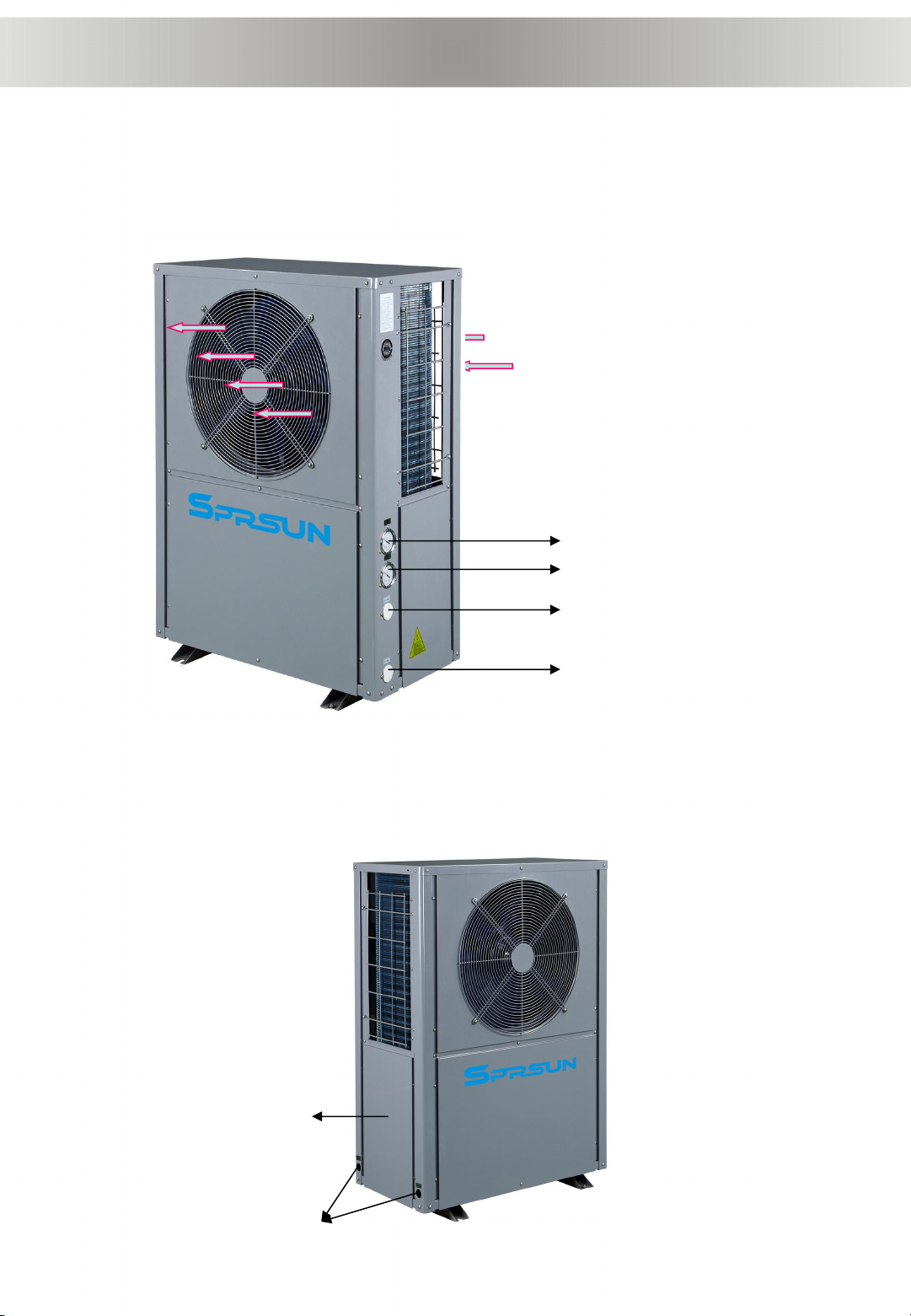
To know the product from exterior
High pressure gauge
Low pressure gauge
Water outlet
Water inlet
Air inlet
Air outlet
Electric
box plate
Cable
holes
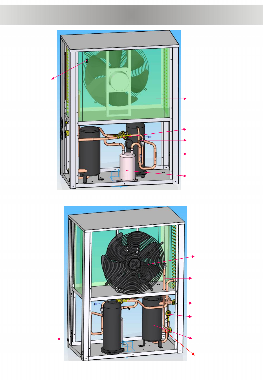
Important parts in heat pump
T1
EVA
4WV
T3
G-L
Fan
T4
T5
EEV
CONCOM
T2
T6
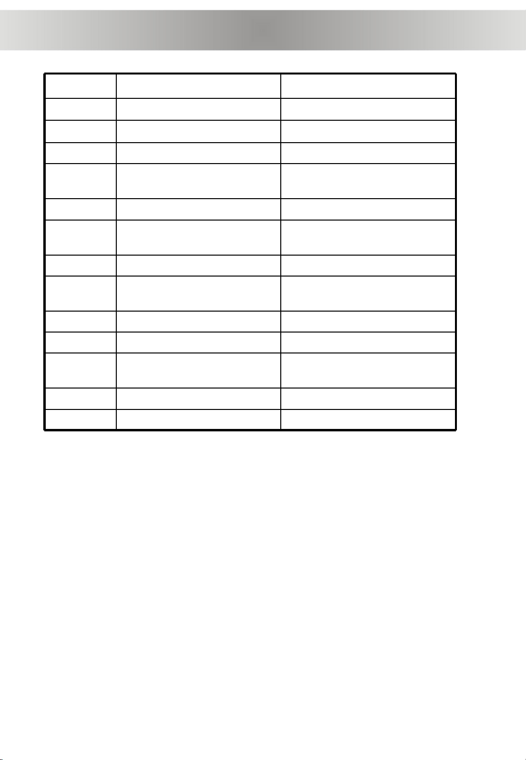
Important parts in heat pump
Code
Name
Remarks
T1
Ambient temp sensor
Connect to port CN11 on PCB
T2
Outlet gas temp sensor
Connect to port CN12 on PCB
T3
Inlet gas temp sensor
Connect to port CN8 on PCB
T4
Air heat exchanger coil temp
sensor
Connect to port CN9 on PCB
T5
Outlet water temp sensor
Connect to port CN3 on PCB
T6
Floor heating water temp
sensor
Connect to port CN6 on PCB
Fan
Fan motor
EVA
Evaporator
Source side air-gas heat
exchanger
G-L
Gas-liquid separator
COM
Compressor
CON
Condenser
Load side water-gas heat
exchanger
EEV
Electronic expansion valve
4WV
Four way valve
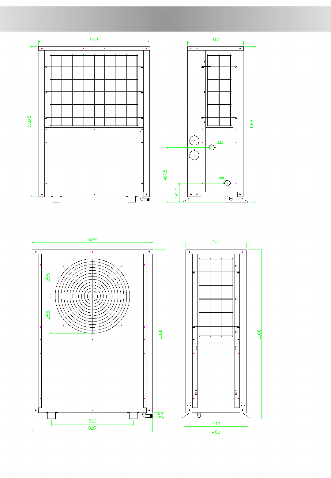
Heat pump size
Back view Right view
Front view Left view
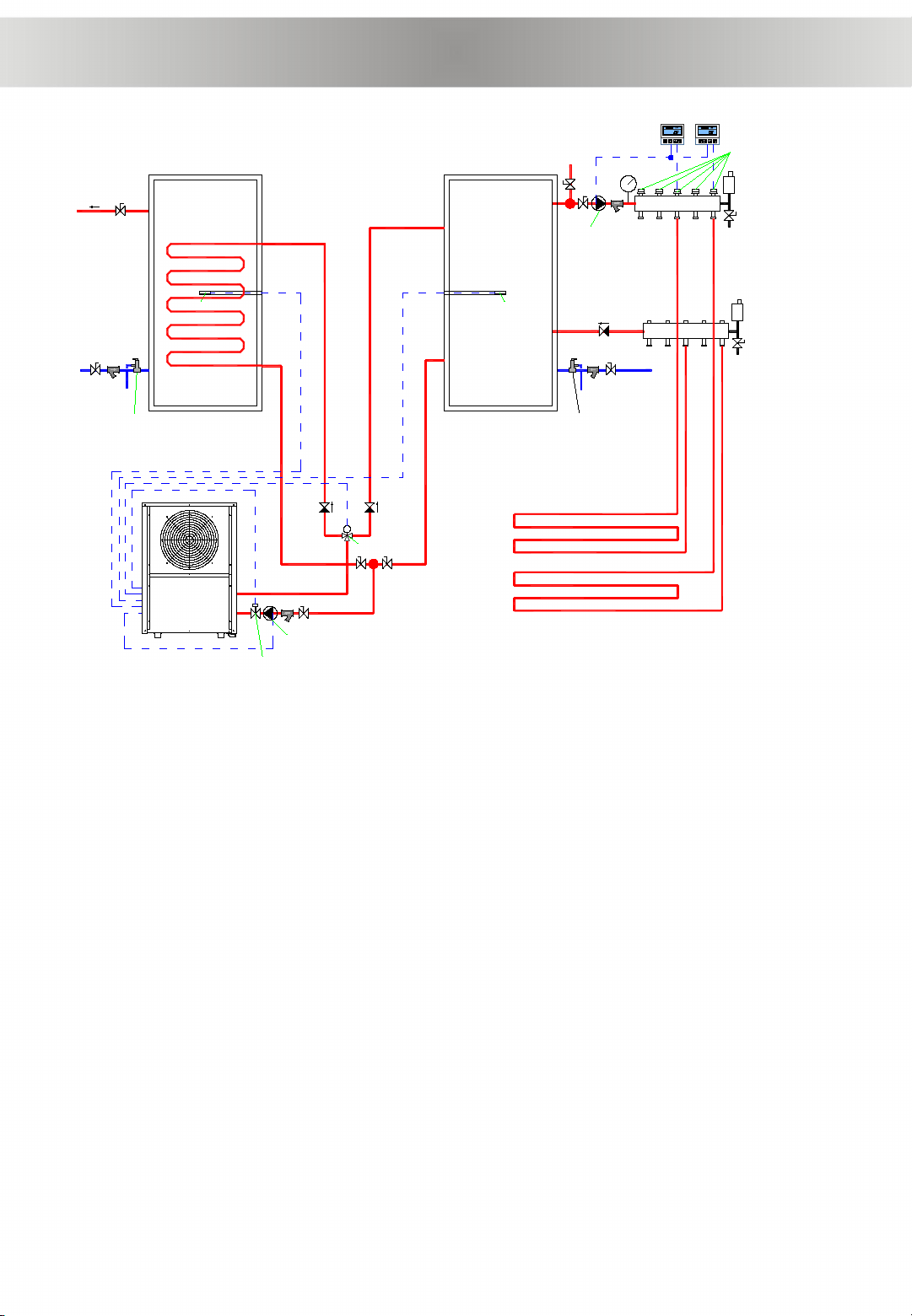
M
Hot water
outlet
Connect to
city water
Hot
water
tank
AC water
tank
Connect to
city water
T1 T2
Heat pump
3WV
P1
P2
Floor heating
Room thermostat
Special valve for floor
heating loop
Water separator
Water collector
WFS
F1
F2 F3
F4
NRV2NRV1
NRV3
SV2SV1
Installation diagram

1. Hot water tank temp sensor (T1)
The sensor should be put in the sensor tube which is
installed in hot water tank.
2. Floor heating water temp sensor (T2)
2.1 Floor heating temp sensor has been installed on the
inlet water pipe inside heat pump before leave factory.
2.2 If floor heating system doesn’t install water tank,
installer needn’t deal with the temp sensor (we don’t
suggest the system without floor heating water tank)
2.3 If floor heating system has water tank, installer should
remove the sensor from inlet pipe and install it in water
tank (we suggest install a floor heating water tank).
Note: Water temp sensors probe can’t touch water directly,
should be put in sensor tube which is installed in water
tank, like the drawing.
Introduction of the system
3. Heat pump circulating water pump (P1)
3.1 This water pump is controlled by heat pump controller.
3.2 Hot water side and floor heating side share the circulating water pump.
3.3 By setting parameter F5 through password 0814, installer can set P1 stop or
non-stop when both hot water and floor heating side have reached preset temp.
3.4 P1 rated water flow is: 1820L/H, head should be ≥5m + water pressure drop
of other parts outside heat pump.
4. Floor heating terminal water pump (P2)
4.1 This water pump is not controlled by heat pump controller, but by floor heating
room thermostat. When any floor heating start, P2 will start, when all floor heating
stop, P2 will stop.
4.2 The wiring diagram of P2 connect to room thermostat can refer to following
parts.

5. Three way valve (3WV):
5.1 Three way valve is controlled by heat pump controller.
5.2 When room linkage switch is connected: hot water is priority, means if both hot water
side and floor heating side need be heated, the three way valve will change to hot
water side, until hot water tank reach preset temp, then the valve will change to floor
heating side. If hot water needn’t be heated, the three way valve will stat at floor
heating side.
5.3 When room linkage switch is disconnected: the three way valve will only stay at hot
water side.
6. Water flow switch (WFS)
6.1 Water flow switch must be installed.
6.2 Because factory hasn’t install the water flow switch in heat pump, so installed should
install it outside heat pump
6.3 Water flow switch is controlled by heat pump controller, input ON/OFF signal to
controller, the port is dry contact.
7. Water pipes:
7.1 Circulating water pipe size should be DN25 (PPR pipe is Φ32), water pipe connector
on heat pump is DN25, copper material, internal thread.
7.2 Water pipes must be insulated.
8. About water filled in floor heating pipe
8.1 The water must be purified.
8.2 The water is suggested mixed anti-freeze (same as anti-freeze in car). Because some
place is very cold, and if user leave home for long time, and need turn off the heat
pump, floor heating system may ice up.
Introduction of the system

8. About hot water tank
8.1 Because the three way valve, a coil heat exchanger must be installed in hot
water tank. Otherwise, the sanitary hot water will be mixed with floor heating water.
8.2 The coil heat exchanger capacity should be about 18KW. And the inner
diameter of coil should be ≥DN25. If <DN25, can install two coil in parallel.
8.3 Hot water tank is suggested to be pressured type. Because heat pump
controller doesn’t have cool water compensating controlling function.
8.4 Hot water tank compensating water pipe must be connected to city water
system. And make sure the pressure of city water is stable and ≥0.15Mpa
9. Floor heating water tank
9.1 The water tank is suggested to be pressured type
9.2 Water compensating pipe should be connected to city water. And the valves
must be opened. In case there is leakage or after cleaned Y filter water reduced, can
compensate water automatically.
10. Y type filter (F1-F4)
10.1 Y type filter must be installed on water compensating pipe of water tank.
10.2 Y type filter must be installed in front of P1.
10.3 Y type filter must be installed on water separator of floor heating.
Y type filter should be checked and cleaned if there is abnormal condition.
11. Safe valve (SV1, SV2)
11.1 On the water compensating pipe of water tank, always install a safe valve.
11.2 The safe valve will release water if water tank pressure is over 0.7Mpa to
protect.
11.3 The safe valve have the function of non-return valve when water tank pressure
is less than 0.7Mpa.
Introduction of the system

Heat pump installation notes
1) The heat pump must be installed in open space. Normally is installed on the
roof of house.
2) The unit should be placed in dry and well-ventilated environment. If the
environment is humid, electronic components may get corroded or short circuit.
3) Heat pump mustn’t be installed in the environment where corrosive, volatile, or
flammable liquid or gas exists.
4) Because of the noise is a little loud, please don’t install the heat pump near
bedroom or living room or meeting room.
5) The bottom of the heat pump should be at least 50cm higher than ground,
because rain water, snow may enter inside if the installation is on ground.
Heat pump can be installed on concrete basic or steel support.
6) Please install a shed for the heat pump, otherwise, rain water can reduce the
lifetime of the shell, and snow may cover the air outlet.
7) Water drainage ditch should be set around the heat pump, when heat pump is
working, there is condensing water flow down, or when defrosting, there are
plenty of water flow down too.
8) Heat pump should far away from kitchen exhaust, because the finned tube is
not easy to clean if there is oil on it.
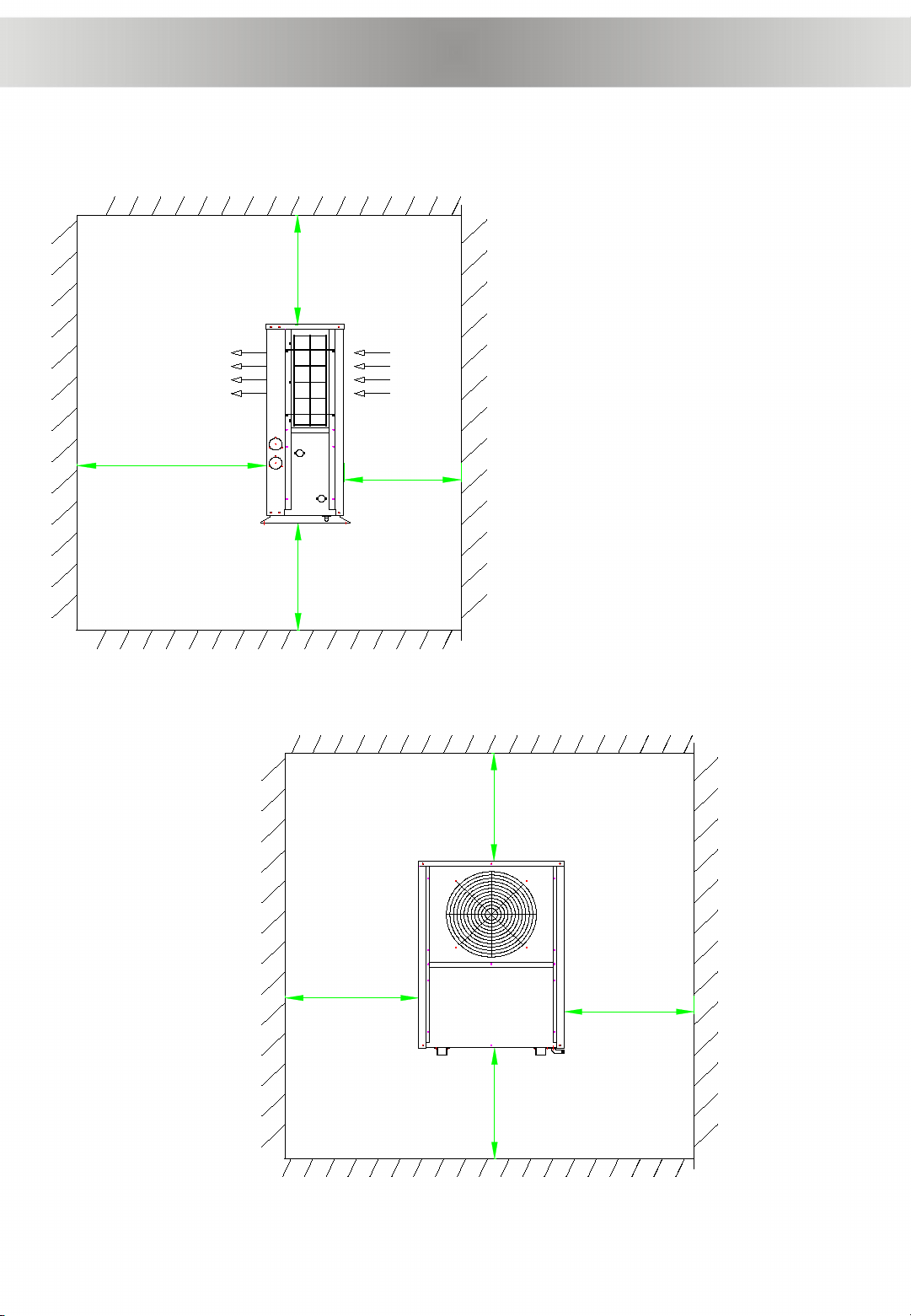
≥0.5m
≥0.5m
≥2m
≥0.5m
Top side
Ground
Front
side
Back
side
2. Installation
2.4 Distances to barrier and ground
≥0.5m
≥1m
≥0.5m
≥0.5m
Top side
Ground
Front
side
Back
side

Other notes of installation
1) Heat pump must be installed on flat concrete blocks or a raised concrete
platform, or steel bracket.
2) Between heat pump and basic or bracket, at leas 4pcs anti-shock pads
should be placed
Concrete basic Steel bracket
Anti-shock pad
Expansion bolt
3) Before make basic or bracket, please check heat pump dimension
4) Before fix heat pump on basic, please confirm heat pump direction according to
project design.
5) Normally use expansion bolt to fix heat pump on concrete basic.
6) Make sure circulating water pipe must be ≥DN25 (or PPR32), and pipes must be
insulated.
7) When install water temp sensor on pipe or in water tank, make sure temp
sensor will not touch water directly, best through a sensor tube. Like below
picture.
Wiring diagram
Secondary
AC-N
OUT1
CN1
CN2
Electric expansion valve
COM
Primary
N input
S3
Figure
ON
S2
S1
COM2 IN1 IN2 IN3 IN4 IN5 IN6 IN7 IN8
Compressor
OUT2 OUT3 OUT4 OUT5 OUT6 OUT7 OUT8
Communication
CN1 CN2 CN3 CN6 CN8 CN9 CN11 CN12 CN13 CN14
AR
B
C
GND 12V
GND
Cycle
heating
Instant + cycle
heating
1 phase
3 phase
S4
Hot water
Swimming pool
Tank
L N
Fan
motor
A1 A2
1L1 3L2 5L3
2T1 4T2 6T3
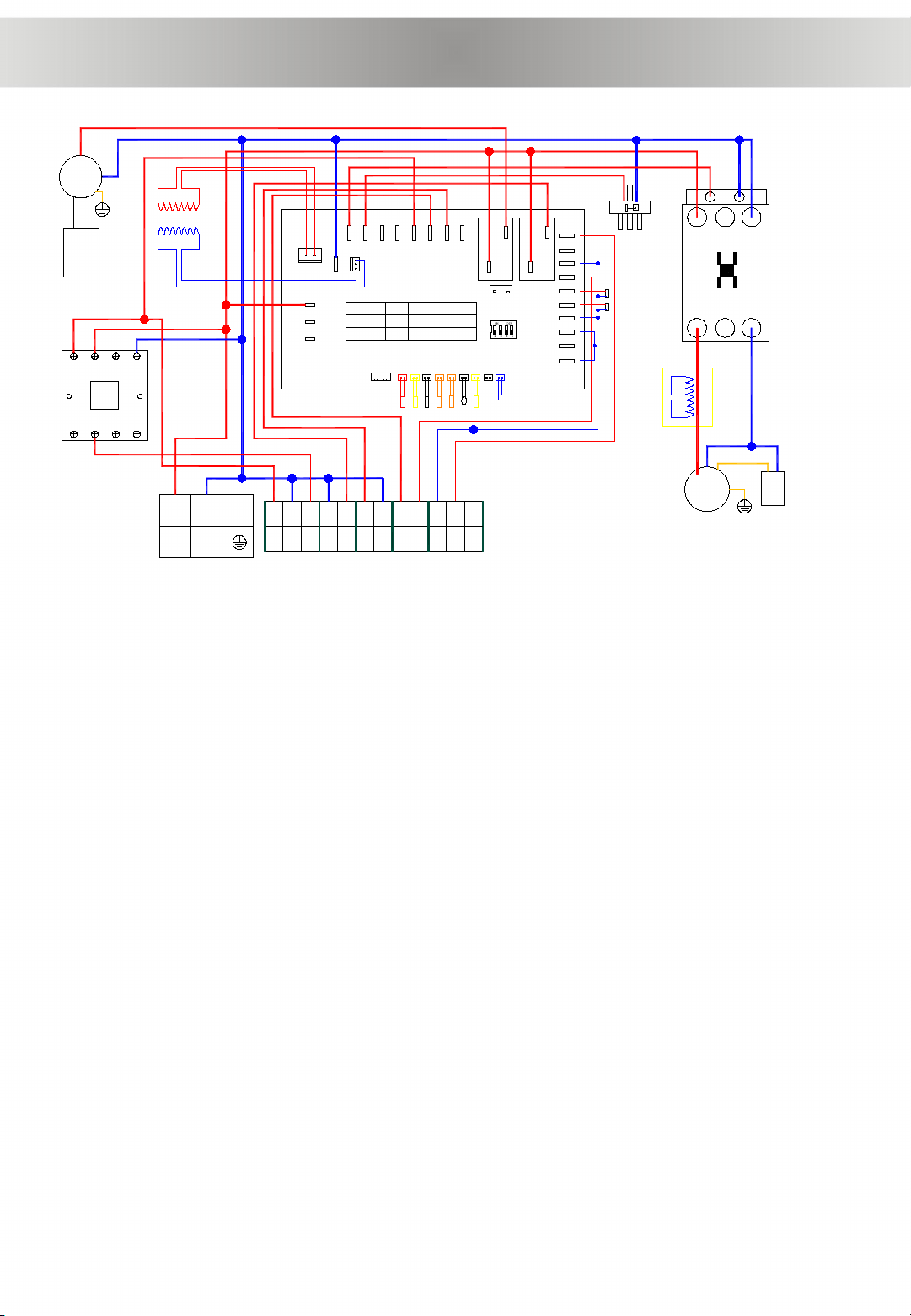
220V/50Hz/1ph single compressor system
wiring diagram
Fan motor
capacitance
Transformer
Current
transformer
Compressor
CS
R
Compressor
capacitance
4-way valve
Solenoid valve A
3-way valve
A/C electric heater
Hot water electricheater
Solenoid valve B
L input
Fan motor
L input
Cycle water pump
Linkage
Water pressure switch
Water flow switch
High pressure switch
Low pressure switch
High water level
Low water level
S
T
Standby
Standby
floor heating
Air HE coil
Outlet gas
Inlet gas
Air
Standby
Current
4-way valve
high pressure switch
low pressure switch
6 5 4 3
7 8 1 2
Cycle water pump
Water flow
Room Linkage
floor heating valve
hot water valve
N
Crankcase heater
N
Outlet water
room linkage
Hot water electric heater
Floor heating electric heater
REMARKS:
The max current of the hot water cycle water pump is 10A
The max current of the Hot water electric heater is 6A
The max current of the floor heating electric heater is 6A
N
COM
COM

Cycle water pump
Water flow
Room Linkage
Floor heating valve
hot water valve
Hot water electric heater
Floor heating electric heater
1 N 2 N N3 4 5 6 F 7 F
F a c t o r y s i d e
I n s t a l l e r s i d e
Terminal details of wiring
1. Floor heating valve:
When floor heating side work, 3-way valve coil get electricity. The terminal supply
220V/1ph voltage.
2. Hot water valve:
When hot water side work, 3-way valve coil loss electricity. The terminal supply
220V/1ph voltage.
3. Cycle water pump:
Rated current should be less than 12A, and power supply is 220V/1ph, if the
current is larger than 12A, should through AC contactor, like below drawing.
4. Hot water electric heater:
Max carrying current is 6A. 220V/50Hz/1ph. If electric heater input power is >1KW,
should though a AC contact to connect to the terminal.

5. Floor heating electric heater:
Max carrying current is 6A. 220V/50Hz/1ph.
(This terminal is optional, it can be chassis electric heater of heat pump too. When place
your order from factory, If select there is chassis electric heater, then floor heating electric
heater will not be included, but will change to chassis electric heater)
6. Water flow switch:
It is ON/OFF input signal, dry contact.
We didn’t install water flow switch inside, please install the water flow switch on water
pipe and connect the wire line to water flow terminals. If don’t install water flow switch,
please bridge connecting it.
7. Room linkage:
It is ON/OFF input signal, dry contact.
At hot water + heating mode:
If room linkage connects, heat pump will performs heating + hot water mode.
If room linkage disconnects, heat pump will performs hot water mode only.
Factory have connects the room linkage switch manually.
If installer want that when any floor heating start, heat pump performs heating + hot
water mode, when no floor heating work, heat pump only performs hot water mode, can
connect all room thermostat to the linkage. Drawing details can refer to below drawing.

Communication
CN1 CN2 CN3 CN6 CN8 CN9 CN11 CN12 CN13 CN14
Tank
floor heating
Air HE coil
Outlet gas
Inlet gas
Air
Standby
Current
Outlet water
Communication: connect operating panel
Tank: Hot water tank temp sensor (installer should install the probe in tank)
Outlet water: Outlet water temp sensor (has been installed in heat pump)
Air HE coil: Source side (air) heat exchanger coil temp sensor (has been installed in
heat pump)
Outlet gas: outlet gas temp sensor of compressor (has been installed in heat pump)
Inlet gas: Inlet gas temp sensor of compressor (has been installed in heat pump)
Air: ambient air temp sensor (has been installed in heat pump)
Floor heating: floor heating water temp sensor (has been installed in heat pump,
installer can move the probe into floor heating water tank)
Current: detect compressor current (has connected by factory)
Analog signal input
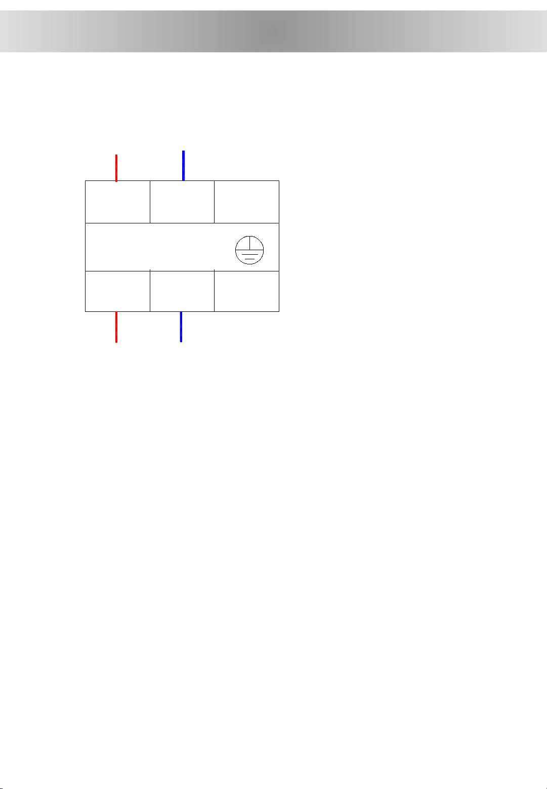
Power supply terminal block
L N Power Supply
Input
Output
Size of power supply line:
L line: 1.5mm2
N line: 1.5mm2
Voltage: 220V~240V/50Hz/1Ph
Max working current: 17A
Circuit breaker: 32A

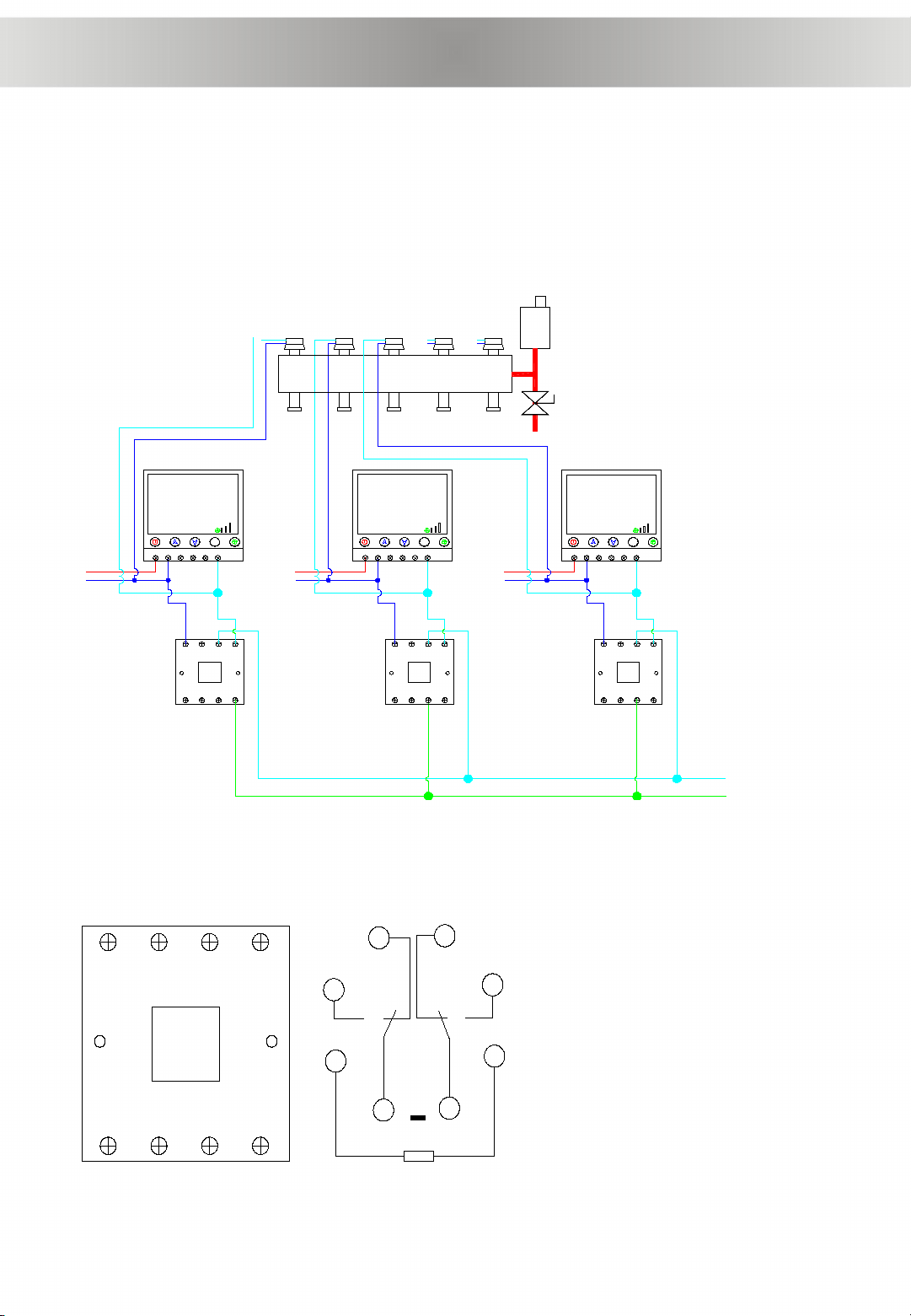
For floor heating system, if want P2 (heating system water pump)
stops when all floor heating loops needn’t work, can connect all the
room thermostat to P2h, the wiring diagram as below.
Wiring diagram of all room thermostat control water pump (P2)
AC 220V
L
N
P2
L1 L3 L5
T2 T4 T6
L1 L3 L5
T2 T4 T6
L1 L3 L5
T2 T4 T6
AC 220V
L
N
AC 220V
L
N
Water separator
AC
contactor
M
L N H M L V
20C°
M
23:25
L N H M L V
20C°
M
23:25
L N H M L V
20C°
M
23:25
Room
thermostat
Floor heating
water separator
Wiring diagram of all room thermostat connect to room linkage terminal
AC 220V
L
N
Room
linkage
AC 220V
L
N
AC 220V
L
N
Water separator
L N H M L V
20C°
M
23:25
L N H M L V
20C°
M
23:25
L N H M L V
20C°
M
23:25
65
4
3
7 8 1 2
65
4
3
7 8 1 2
65
4
3
7 8 1 2
Change-over
switch
Room
thermostat
Floor heating
water separator
If want heat pump only performs at hot water side when floor heating side no need,
can connect all room thermostats to “Room linkage” terminal.
6
5
4
3
7 8 1 2
2
1
8
7
6
54
3
coil
2 and 7 input side connect 220V
power supply,output side connect
coil
1,3,4 are a group,1 and 3 normal
open,1 and 4 normal close。when
coil loss electricity, 1 and 4
connects,when coil get electricity,1
and 3 connects。
8,6,5 are a group. 8 and 5 normal
close,8 and 6 normal open. when
coil loss electricity, 5 and 8
connects,when coil get
electricity,6 and 8 connects.
This manual suits for next models
1
Table of contents
Other SPRSUN Heat Pump manuals

 Series User manual")


 Product data")

