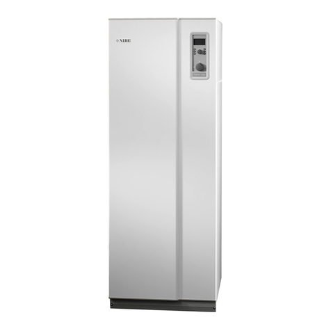
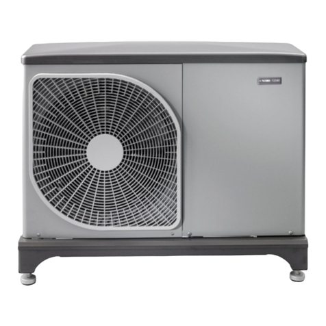
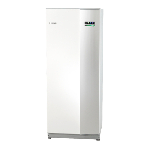
Nibe HBS 05 Series User guide

Installer manual
LEK
HBS 05
HBS 05-6 / 05-12 / 05-16
SPLIT box
IHB EN 1746-1
331901


Table of Contents
41 Important information
4System solution
4Safety information
6Serial number
6Recovery
6Environmental information
7Inspection of the installation
8Checklist: Checks before commissioning
92 Delivery and handling
9Transport and storage
9Assembly
10Supplied components
11Removing the covers
123 The heat pump design
12Component location HBS 05 (EZ102)
13List of components HBS 05 (EZ102)
14Electrical panel
154 Pipe connections
15General
16Connecting refrigerant pipes (not supplied)
17Pipe connection
18Pressure test and leak test
18Vacuum pump
18Filling refrigerant
18Insulating refrigerant pipes
19Pipe coupling heating medium circuit
19Pressure drop, heating medium side
19Docking alternatives
225 Electrical connections
22General
24Electrical components
24Accessibility, electrical connection
24Connection between HBS 05 and AMS 10
25Connection between HBS 05 and VVM
26Connection between HBS 05 and SMO
28Connections
28Connecting accessories
296 Commissioning and adjusting
29Preparations
29Start-up and inspection
29Inspection of the installation
30Readjusting, heating medium side
30Adjustment, charge flow
317 Control - Heat pump EB101
31Heat pump menu 5.11.1.1
328 Disturbances in comfort
32Troubleshooting
379 Alarm list
4010 Accessories
4111 Technical data
41Dimensions
42Technical specifications
44Electrical circuit diagram
46Item register
51Contact information
3Table of Contents |HBS 05

System solution
HBS 05 is intended for installation with outdoor
module (AMS 10) and indoor module (VVM) or con-
trol module (SMO) for a complete system solution.
Safety information
This manual describes installation and service procedures
for implementation by specialists.
The manual must be left with the customer.
This appliance can be used by children
aged from 8 years and above and per-
sons with reduced physical, sensory or
mental capabilities or lack of experience
and knowledge if they have been given
supervision or instruction concerning use
of the appliance in a safe way and under-
stand the hazards involved. The product
is intended for use by experts or trained
users in shops, hotels, light industry,
farming and similar environments.
Children must be instructed/supervised
to ensure that they do not play with the
appliance.
Do not allow children to clean or main-
tain the appliance unsupervised.
This is an original manual. It may not be
translated without the approval of NIBE.
Rights to make any design or technical
modifications are reserved.
©NIBE 2017.
Symbols
NOTE
This symbol indicates danger to person or ma-
chine .
Caution
This symbol indicates important information
about what you should observe when maintain-
ing your installation.
TIP
This symbol indicates tips on how to facilitate
using the product.
Marking
The CE mark is obligatory for most products sold
in the EU, regardless of where they are made.
CE
Classification of enclosure of electro-technical
equipment.
IP21
Danger to person or machine.
!
Read the User Manual.
Safety precautions
Caution
Install the system in full accordance with this installation
manual.
Incorrect installation can cause bursts, personal injury, water leaks,
refrigerant leaks, electric shocks and fire.
Pay attention to the measurement values before working on
the cooling system, especially when servicing in small rooms,
so that the limit for the refrigerant’s concentration is not ex-
ceeded.
Consult an expert to interpret the measurement values. If the refri-
gerant concentration exceeds the limit, there may be a shortage
of oxygen in the event of any leak, which can cause serious injury.
Use original accessories and the stated components for the
installation.
If parts other than those stated by us are used, water leaks, electric
shocks, fire and personal injury may occur as the unit may not work
properly.
Ventilate the working area well – refrigerant leakage may occur
during service work.
If the refrigerant comes into contact with naked flames, poisonous
gas is created.
Install the unit in a location with good support.
Unsuitable installation locations can cause the unit to fall and cause
material damage and personal injury. Installation without sufficient
support can also cause vibrations and noise.
Ensure that the unit is stable when installed, so that it can
withstand earthquakes and strong winds.
Unsuitable installation locations can cause the unit to fall and cause
material damage and personal injury.
The electrical installation must be carried out by a qualified
electrician and the system must be connected as a separate
circuit.
Power supply with insufficient capacity and incorrect function can
cause electric shocks and fire.
Use the stated cables for the electrical connection, tighten the
cables securely in the terminal blocks and relieve the wiring
correctly to prevent overloading the terminal blocks.
Loose connections or cable mountings can cause abnormal heat
production or fire.
Check, after completed installation or service, that no refriger-
ant leaks from the system in gas form.
If refrigerant gas leaks into the house and comes into contact with
an aerotemp, an oven or other hot surface, poisonous gases are
produced.
Switch off the compressor before opening/breaching the refri-
gerant circuit.
If the refrigerant circuit is breached /opened whilst the compressor
is running, air can enter the process circuit. This can cause unusually
high pressure in the process circuit, which can cause bursts and
personal injury.
Switch off the power supply in the event of a service or inspec-
tion.
HBS 05Chapter 1 | Important information4
1 Important information

If the power supply is not shut off, there is a risk of electric shocks
and damage due to the rotating fan.
Do not run the unit with removed panels or protection.
Touching rotating equipment, hot surfaces or high voltage parts
can cause personal injury due to entrapment, burns or electric
shocks.
Cut the power before starting electrical work.
Failure to cut the power can cause electric shocks, damage and in-
correct function of the equipment.
Care
Carry out the electrical installation with care.
Do not connect the ground lead to the gas line, water line, lightning
conductor or telephone line's ground lead. Incorrect grounding
can cause unit faults such as electric shocks due to short-circuiting.
Use main switch with sufficient breaking capacity.
If the switch does not have sufficient breaking capacity, malfunc-
tions and fire can occur.
Always use a fuse with the correct rating in the locations where
fuses are to be used.
Connecting the unit with copper wire or other metal thread can
cause unit breakdown and fire.
Cables must be routed so that they are not damaged by metal
edges or trapped by panels.
Incorrect installation can cause electric shocks, heat generation
and fire.
Do not install the unit in close proximity to locations where
leakage of combustible gases can occur.
If leaking gases collect around the unit, fire may occur.
Do not install the unit where corrosive gas (for example nitrous
fumes) or combustible gas or steam (for example thinner and
petroleum gases) can build up or collect, or where volatile
combustible substances are handled.
Corrosive gas can cause corrosion to the heat exchanger, breaks
in plastic parts etc. and combustible gas or steam can cause fire.
Do not use the unit where water splashes may occur, for ex-
ample in laundries.
The indoor section is not waterproof and electric shocks and fire
can therefore occur.
Do not use the unit for specialist purposes such as for storing
food, cooling precision instruments, freeze-conservation of
animals, plants or art.
This can damage the items.
Do not install and use the system close to equipment that
generates electromagnetic fields or high frequency harmonics.
Equipment such as inverters, standby sets, medical high frequency
equipment and telecommunications equipment can affect the unit
and cause malfunctions and breakdowns. The unit can also affect
medical equipment and telecommunications equipment, so that
it functions incorrectly or not at all.
Do not install the outdoor unit in the locations stated below.
- Locations where leakage of combustible gas can occur.
- Locations where carbon fibre, metal powder or other powder
that can enter the air.
- Locations where substances that can affect the unit, for example,
sulphide gas, chlorine, acid or alkaline substances can occur.
- Locations with direct exposure to oil mist or steam.
- Vehicles and ships.
- Locations where machines that generate high frequency harmon-
ics are used.
- Locations where cosmetic or special sprays are often used.
- Locations that can be subjected to direct salty atmospheres. In
this case, the outdoor unit must be protected against direct intakes
of salty air.
- Locations where large amounts of snow occur.
- Locations where the system is exposed to chimney smoke.
If the bottom frame of the outdoor section is corroded, or in
any other way damaged, due to long periods of operation, it
must not be used.
Using an old and damaged frame can cause the unit to fall and
cause personal injury.
If soldering near the unit, ensure that solder residue does not
damage the drip tray.
If solder residue enters the unit during soldering, small holes can
appear in the tray resulting in water leakage. To prevent damage,
keep the indoor unit in its packing or cover it.
Do not allow the drainage pipe to exit into channels where
poisonous gases, containing sulphides for example, can occur.
If the pipe exits into such a channel, any poisonous gases will flow
into the room and seriously affect the user's health and safety.
Insulate the unit's connection pipes so that the ambient air
moisture does not condense on them.
Insufficient insulation can cause condensation, which can lead to
moisture damage on the roof, floor, furniture and valuable personal
property.
Do not install the outdoor unit in a location where insects and
small animals can inhabit.
Insects and small animals can enter the electronic parts and cause
damage and fire. Instruct the user to keep the surrounding equip-
ment clean.
Take care when carrying the unit by hand.
If the unit weights more than 20 kg, it must be carried by two
people. Use gloves to minimize the risk of cuts.
Dispose of any packaging material correctly.
Any remaining packaging material can cause personal injury as it
may contain nails and wood.
Do not touch any buttons with wet hands.
This can cause electric shocks.
Do not touch any refrigerant pipes with your hands when the
system is in operation.
During operation the pipes become extremely hot or extremely
cold, depending on the method of operation. This can cause burn
injuries or frost injuries.
Do not shut off the power supply immediately after operation
has start.
Wait at least 5 minutes, otherwise there is a risk of water leakage
or breakdown.
Do not control the system with the main switch.
This can cause fire or water leakage. In addition, the fan can start
unexpectedly, which can cause personal injury.
5Chapter 1 | Important informationHBS 05

Serial number
You can find the serial number (PF3) under the cover,
both on the front and on top of HBS 05.
UN
UN
PF3
PF3
Caution
You need the product's (14 digit) serial number
for servicing and support.
Recovery
Leave the disposal of the packaging to the in-
staller who installed the product or to special
waste stations.
Do not dispose of used products with normal
household waste. It must be disposed of at a
special waste station or dealer who provides this type of
service.
Improper disposal of the product by the user results in
administrative penalties in accordance with current legis-
lation.
Environmental information
The equipment contains R410A, a fluorinated green-
house gas with a GWP value (Global Warming Potential)
of 2088. Do not release R410A into the atmosphere.
HBS 05Chapter 1 | Important information6

Inspection of the installation
Current regulations require the heating installation to be inspected before it is commissioned. The inspection must
be carried out by a suitably qualified person. Fill in the page for information about installation data in the User
manual.
DateSignatureNotesDescription
✔
Heating medium (page 15)
System flushed
System vented
Particle filter
Shut-off and drain valve
Charge flow set
Electricity (page 22)
Fuses property
Safety breaker
Earth circuit-breaker
Heating cable type/effect
Fuse size, heating cable (F3)
Communication cable connected
AMS 10 addressed (only when cascade
connection)
When installing AMS 10-6 / HBS 05-6,
check that the software version of the in-
door module/control module is at least
v8320.
Miscellaneous
Condensation water pipe
Caution
HBS 05-6 only compatible with AMS 10-6
HBS 05-12 only compatible with AMS 10-8 / AMS 10-12.
HBS 05-16 only compatible with AMS 10-16.
7Chapter 1 | Important informationHBS 05

Checklist: Checks before commissioning
CheckedNotesRefrigerant system
Pipe length
Height difference
Pressurization test
Leak testing
End pressure vacuum
Pipe insulation
CheckedNotesElectrical installation
Property's main fuse
Group fuse
Current limiter/current sensor
KVR 10
CheckedNotesCooling
Pipe system, condensation insulation
HBS 05Chapter 1 | Important information8

Transport and storage
HBS 05 should be transported and stored vertically in a
dry place.
NOTE
Ensure that the heat pump cannot fall over
during transport.
Assembly
■It is recommended that HBS 05 is installed in a room
with existing floor drainage, most suitably in a utility
room or boiler room.
■The brackets for HBS 05 are screwed to the wall using
the enclosed screws. Mounting template enclosed.
■Route pipes so they are not fixed to an internal wall
that backs on to a bedroom or living room.
■Ensure that there is approx. 800 mm free space in front
of and 400 mm above the product for any future ser-
vice. Ensure that there is sufficient space above the
machine for pipework and valves.
Caution
HBS 05 will end up approx. 10 mm out from
the wall when it has been mounted on the
brackets.
NOTE
Condensation hose (WP3) must be connected
to holes in the underside of HBS 05.
Mounting the SPLIT box HBS 05
LEK
21
LEK
3
1. Position the enclosed mounting template horizontally
against the wall. (See the dimensions on the mounting
template.) Mark for drilling holes.
LEK
21
LEK
3
2. Screw the brackets to the wall using the enclosed
screws.
UN
3. Install HBS 05 on the brackets. Finally, install the cover.
9Chapter 2 | Delivery and handlingHBS 05
2 Delivery and handling

Installation area
There should be free space on at least one side, for any
service to HBS 05 in the future. Ensure that there is also
approx. 80 cm free space in front of HBS 05.
Recommendation for positioning on wall
LEK
LEK
Placering vägg/hörn. Placering vägg.
Min. 30 cm
Min. 20 cmMin. 20 cm
Recommendation for positioning on wall / in corner
LEK
LEK
Placering vägg/hörn. Placering vägg.
Min. 40 cm
Min. 40 cm
Supplied components
Filterball (G1").
LEK
Condensation hose (WP3)
LEK
Brackets kit
HBS 05Chapter 2 | Delivery and handling10

Removing the covers
HBS05
LEK
LEK
LEK
LEK
11Chapter 2 | Delivery and handlingHBS 05

Component location HBS 05 (EZ102)
UN
UN
AA23
AA23-X100
X1
AA23-X1 A23-F3
BT15
BP4
BT3
XL53XL52XL1XL2UB3UB1 UB2
BT12
EP2
HZ2
PF1
PF3
AA23-X4 WP3
AA23-S3
PF4
PF3
HBS 05Chapter 3 | The heat pump design12
3 The heat pump design

List of components HBS 05
(EZ102)
Pipe connections
Climate system supplyXL1
Climate system returnXL2
Connection, gas lineXL52
Connection, liquid lineXL53
Valves etc.
Heat exchangerEP2
Drying filterHZ2
Filterball (supplied)QZ2
Electrical components
Communication boardAA23
Fuse for external heating cableAA23-F3
DIP switch, addressing of outdoor unitAA23-S3
Terminal block, incoming supply, connec-
tion of KVR
AA23-X1
Terminal block, communication with in-
door module / control module
AA23-X4
Terminal block, communication outdoor
module AMS 10
AA23-X100
Terminal block, incoming supplyX1
Sensor, thermostats
Pressure sensor, high pressureBP4
Temperature sensor, heating medium, returnBT3
Temperature sensor, condenser, supplyBT12
Temperature sensor, fluid pipeBT15
Miscellaneous
Rating platePF1
Serial number platePF3
Sign, pipe connectionsPF4
Cable glandUB1
Cable glandUB2
Cable glandUB3
Condensation hoseWP3
Designations in component locations according to standard IEC 81346-1 and 81346-2.
13Chapter 3 | The heat pump designHBS 05
Electrical panel
HBS 05
UN
UN
AA23
AA23-S3
AA23-X1
AA23-X4
AA23-X100
AA23-F3
X1
UN
1 2 3 4 5 6
X1
AA23
AA23-S3
AA23-X100
AA23-X4
AA23-F3
AA23-X1
Electrical components HBS 05
Communication boardAA23
Fuse for external heating cableAA23-F3
DIP switch, addressing of outdoor unitAA23-S3
Terminal block, incoming supply, connec-
tion of KVR
AA23-X1
Terminal block, communication with in-
door module / control module
AA23-X4
Terminal block, communication outdoor
module AMS 10
AA23-X100
Terminal block, incoming supplyX1
Designations in component locations according to standard IEC 81346-1 and 81346-2.
HBS 05Chapter 3 | The heat pump design14

General
Pipe installation must be carried out in accordance with
current norms and directives.
AMS 10 and HBS 05 work up to a return temperature of
approx. 55°C and an outgoing temperature from the
heat pump of approx. 58 °C.
HBS 05 is not equipped with shut off valves on the water
side, these must be installed to facilitate any future ser-
vicing.
When docking with HBS 05 free flow in the climate sys-
tem is recommended for correct heat transfer. This can
be achieved by use of a bypass valve. If free flow cannot
be ensured, it is recommended that a buffer tank (NIBE
UKV) is installed.
15Chapter 4 | Pipe connectionsHBS 05
4 Pipe connections

Connecting refrigerant pipes
(not supplied)
Install the refrigerant pipes between the outdoor module
AMS 10 and HBS 05.
Installation must be carried out in accordance with cur-
rent norms and directives.
Parameters AMS 10
■Maximum pipe length, AMS 10 (L): 30 m.
■Maximum height difference (H): ±7m.
L
H
L
H
HBS05
HBS05
AMS10
AMS10
Pipe dimensions and materials
AMS 10-6
Liquid pipeGas pipe
Ø6.35 mm (1/4")Ø12.7 mm (1/2")Pipe dimension
Flare - (1/4")Flare - (1/2")Connection
Copper quality SS-EN 12735-1 or
C1220T, JIS H3300
Material
0.8 mm1.0 mmMinimum material
thickness
AMS 10-8, AMS 10-12 and AMS 10-16
Liquid pipeGas pipe
Ø9.52 mm (3/8")Ø15.88 mm (5/8")Pipe dimension
Flare - (3/8")Flare - (5/8")Connection
Copper quality SS-EN 12735-1 or
C1220T, JIS H3300
Material
Liquid pipeGas pipe
0.8 mm1.0 mmMinimum material
thickness
HBS 05Chapter 4 | Pipe connections16

Pipe connection
Pipe connection, refrigerant pipe
■Perform pipe installation, on the refrigerant side
between outdoor module (AMS 10) and SPLIT box
(HBS 05), with the service valves (QM35, QM36) closed.
■Connect refrigerant pipes between the service valves
(QM35 and QM36) on the outdoor module (AMS 10)
and the connections (XL52 and XL53) on SPLIT box
(HBS 05).
UN
UN
XL53
XL52XL1
XL2
■Ensure that water or dirt does not enter the pipes.
■Bend the pipes with as large a radius as possible (at
least R100~R150). Do not bend a pipe repeatedly. Use
a bending tool.
■Connect the flare connector and tighten to the follow-
ing torque. Use the "Tightening angle" if a torque
wrench is not available.
Recommen-
ded tool
length
(mm)
Tightening
angle (°)
Tightening
torque
(Nm)
Outer dia-
meter, cop-
per pipe
(mm)
15045~6014~18Ø6.35
20030~4534~42Ø9.52
25030~4549~61Ø12.7
30015~2068~82Ø15.88
NOTE
Gas shielding must be used when soldering.
Flare connections
Expansion:
A
A (mm)Outer diameter, copper pipe (mm)
9.1Ø6.35
13.2Ø9.52
16.6Ø12.7
19.7Ø15.88
Ejection:
B
B, with a conven-
tional tool (mm)
B, with an
R410A tool
(mm)
Outer diameter,
copper pipe
(mm)
1.0~1.50.0~0.5Ø6.35
0.7~1.30.0~0.5Ø9.52
1.0~1.50.0~0.5Ø12.7
0.7~1.30.0~0.5Ø15.88
(Follow instructions for the tool used.)
17Chapter 4 | Pipe connectionsHBS 05

Pressure test and leak test
Both HBS 05 and AMS 10 are pressure tested and leak
tested at the factory, but the pipe connections between
the products must be checked after installation.
NOTE
The pipe connection between the products
must be pressure tested and leak tested accord-
ing to the applicable regulations after installa-
tion.
Under no circumstances must a type of medium
other than nitrogen be used when pressurising
or flushing the system.
Vacuum pump
Use a vacuum pump to evacuate all air. Apply suction
for at least one hour and end pressure after evacuation
must be 1 mbar (100 Pa, 0.75 Torr or 750 micron) abso-
lute pressure.
If the system has remaining moisture or a leak, the vacu-
um pressure will rise after completed evacuation.
Vacuum
pump
Serviceventil, gas
Mätuttag
Manometer
Serviceventil, vätska
Service valve, liquid
Service valve, gas
Measurement outlet
Pressure
gauge
Vacuum
pump
TIP
For a better end result and to quicken the
evacuation, the following points must be fol-
lowed.
■The connection lines must be as large and
short as possible.
■Evacuate the system down to 4 mbar and fill
the system with dry nitrogen to atmospheric
pressure to the finish the evacuation.
Filling refrigerant
AMS 10 is delivered complete with the refrigerant re-
quired for the installation of refrigerant pipes up to 15
m in length.
NOTE
For installations with refrigerant pipes up to
15 m in length, no extra refrigerant in addition
to the provided amount needs to be added.
When carrying out pipe connections, pressure tests, leak
tests and vacuuming, the service valves (QM35, QM36)
can be opened, to fill the pipes and HBS 05 with refriger-
ant.
Insulating refrigerant pipes
■Insulate refrigerant pipes (both gas and liquid pipes)
for heat insulation and to prevent condensation.
■Use insulation that can withstand at least 120 °C.
Poorly insulated pipes can cause insulation related
problems and unnecessary cable wear.
Principle:
Wires for connecting indoor
and outdoor units Exterior tape
Gas piping
Insulation
Liquid piping
Wiring
Liquid pipe
Tape
Gas pipe
Insulation
Connections:
Band (accessory) Pipe cover (accessory)
Strap Pipe protection
HBS 05Chapter 4 | Pipe connections18

Pipe coupling heating medium
circuit
■HBS 05 is intended for combination with NIBE outdoor
module (AMS 10) and NIBE indoor module (VVM) or
control module (SMO), in accordance with one of the
system solutions that can be downloaded from the
website www.nibe.eu.
■Install vent valves if the pipe routing requires this to
avoid malfunctions.
■Install the supplied particle filter before the inlet, i.e.
the connection (XL2, HM return) on HBS 05.
■Install the enclosed condensation hose (WP3).
TIP
Position the condensation hose in the
grooves on the underside of HBS 05, either
the right or the left hand side or at the back.
Pressure drop, heating medium
side
HBS 05
0
5
10
15
20
25
30
0,0 0,1 0,2 0,3 0,4 0,5 0,6 0,7 0,8
Fl de [l/s]
Tryckfall [kPa]
Tryckfall HBS05
HBS05-6, -16HBS05-12
Pressure drop HBS05
Pressure drop
[kPa]
Flow [l / s]
Docking alternatives
HBS 05 can be installed in several different ways. The
required safety equipment must be installed in accord-
ance with current regulations for all docking options. To
ensure fault-free operation of the system, it is recommen-
ded to give consideration to the values according to the
table when adjusting the system.
See www.nibe.eu for more docking options.
Installation requirements
HBS 05-16HBS 05-12HBS 05-12HBS 05-6SPLIT box HBS 05
AMS 10-16AMS 10-12AMS 10-8AMS 10-6Compatible outdoor module
Requirements
0.6 MPa (6 Bar)Max pressure, climate system
55 / 45°CHighest recommended supply/return temperat-
ure at dimensioned outdoor temperature
58 °CMax flow line temperature with compressor
7 °CMin supply temperature cooling, HBS 05
25 °CMax supply temp. cooling
0.39 l/s0.29 l/s0.19 l/s0.19 l/sMin flow, climate system, 100 % circulation
pump speed (defrosting flow)
Recommendations
150 l80 l50 l20 lMin volume, climate system during heating,
cooling*
150 l100 l80 l50 lMin volume, climate system during under floor
cooling*
0.79 l/s0.57 l/s0.38 l/s0.29 l/sMax flow, climate system
0.24 l/s0.15 l/s0.12 l/s0.09 l/sMin flow, heating system
0.32 l/s0.20 l/s0.16 l/s0.11 l/sMin flow, cooling system
*Refers to circulating volume.
19Chapter 4 | Pipe connectionsHBS 05

Symbol key
MeaningSymbol
Venting valve
Shut-off valve
Non-return valve
Control valve
Safety valve
Temperature sensor
Expansion vessel
Pressure gauge
P
Circulation pump
Shunt / shuttle valve
Fan
Domestic hot water
Radiator system
Under floor heating systems
HBS 05Chapter 4 | Pipe connections20
This manual suits for next models
7
Table of contents
Other Nibe Heat Pump manuals
Popular Heat Pump manuals by other brands

York
York YLPA 0115SE Installation, operation and maintenance manual

Dimplex
Dimplex LA 22TBS Installation and operating instructions

Atlantic
Atlantic Alfea Extensa A.I. R32 operating manual

Panasonic
Panasonic WH-MHF09G3E8 Service manual

Carrier
Carrier 50SZ Series Installation, Start-Up and Service Instructions

WarmFlow
WarmFlow G Series manual

Viessmann
Viessmann VITOCAL 242-G Installation and service instructions

Bosch
Bosch BOVA Series installation instructions

Daikin
Daikin RXF125KC Removal Procedure

EAS Electric
EAS Electric ETH220VMA instruction manual

Vertiv
Vertiv Liebert MC series Installer/user guide

Gree
Gree GRS-CQ6.0Pd/Na-K Service manual