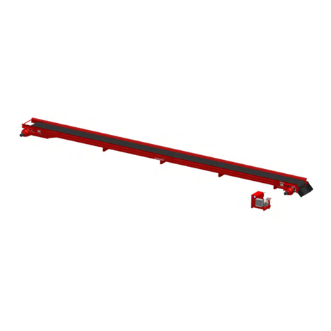
Spudnik 1205 User manual

OWNER’S / OPERATOR’S MANUAL
PART # 290009
MODEL 1205
SUPER STYLE STRAIGHT
CONVEYOR

MISSION STATEMENT
Our mission is to consistently provide
high quality, reliable, safe, and well-designed
products and services to meet or exceed the needs
of our customers.
Operating Manual Overview
The purpose of this Spudnik Operating Manual is to make the user familiar with this
machine and to assure the machine is used for what it has been designed to do.
This Operating Manual contains important information on how to operate this machine
properly and efficiently while maintaining all safetyregulations. Observing and
practicing the information within this Manual can effectively prevent danger, reduce
repair costs and downtimes, while increasing reliability and service life ofthe machine.
The Operating Manual must always be available to users wherever the machine is in use.
The Operating Manual must be read and applied by all persons working on/with the
machine, e.g.
•Operation -including set-up, troubleshooting, care, etc.
•Maintenance –servicing, inspection, repair.
•Transport

Service Centers
Phone:(208)785-0480-Fax: (208)785-1497
E-Mail: [email protected]
Web Site:www.spudnik.com
BLACKFOOT PASCO GRAFTON
584 West 100 North 5802 North Industrial Way 1410 12th St. West
P.O. Box 1045 Pasco, Wa. 99301 Grafton, Nd. 58237
Blackfoot, ID 83221 Phone (509) 543-7166 Phone (701) 352-9603
Phone (208)785-0480 Fax (509) 543-7169 Fax (701) 352-9610
Fax (208)785-1497
HEYBURN PRESQUE ISLE
300 Centennial Dr. 110 Airport Dr.
Heyburn, ID 83336 Presque Isle, Me. 04769
Phone (208)436-8052 Phone (207) 764-4686
Fax (208) 436-9170 Fax (207) 764-4674

TABLE OF CONTENTS
PAGE
Introduction ………………………………………………………………………… 3
Warranty …………………………………………………………………………… 4
Safety ………………………………………………………………………………. 5, 6
Safety Practices ……………………………………………………………………. 7, 8
Safety Label ………………………………………………………………………... 9
Lubrication …………………………………………………………………………. 9
Maintenance ……………………………………………………………………….. 10
Machine Operation ………………………………………………………………… 11
Machine Parts Breakdown
Table Of Contents …………………………………………………………………
12
Electrical Schematics ……………………………………………………………… 30-35
240 VOLTS 1 PHASE = STANDARD 30
208 - 240 VOLTS 3 PHASE = STANDARD 31
480 VOLTS 3 PHASE = STANDARD 32
240 VOLTS 1 PHASE = VARIABLE SPEED 33
208 - 240 VOLTS 3 PHASE = VARIABLE SPEED 34
480 VOLTS 3 PHASE = VARIABLE SPEED 35
Revised: Added Variable Speed Schematic.
4/25/2002 2

INTRODUCTION
Welcome to the SPUDNIK line of potato handling equipment. We appreciate your
decision to make our equipment a part of your operation, and look forward to a long-
term partnership. We strive to put the best quality and workmanship into each of our
machines, and hope as you use your MODEL 1205 SUPER STYLE STRAIGHT
CONVEYOR (SSSC), you will find this to be true. This owner’s / operators manual has
been prepared to aid you in safe operation and service of your Conveyor.
Read manual carefully to learn how to operate your machine safely and within design
limits of machine. Failure to do so could result in personal injury and/or damage to
machine.
This manual is an important part of this machine and should accompany it when moved
from location to location.
Warranty is provided as part of the SPUDNIK EQUIPMENT COMPANY LLC service
program for customers who operate and maintain their equipment as outlined in this
manual.
OWNER REGISTRATION
Name _____________________________________________
Address ___________________________________________
City ______________________________________________
State / Province _____________________________________
Country ___________________________________________
Model Number ____________ Serial Number _____________
Purchase Date _____________________________________
4/25/2002 3

WARRANTY POLICY
1- Warranty on all normal maintenance items such as; rollers, sprockets, roller
chain, belt lacing, and bearings etc. will be for one season (Not to exceed vendor
warranty). A season being 720 Hr. not to exceed 183 days. All other materials and
workmanship will be warranted for one full year from date of purchase. (Some
components carry more than a one-year warranty from the vendor, this will be
passed on to the customer where applicable).
2- No warranty payment will be made for failure of the customer to operate and
maintain the machine according to proper procedures, written or customary.
Machines must be used within reasonable limits.
3- All warranty must be completed within one year of purchase unless an
agreement is made with Spudnik Equipment Company LLC to do otherwise, prior to
the end of the year.
4- No warranty payments will be made without a REQUEST FOR WARRANTY
PAYMENT signed by the customer, and all faulty parts are returned to Spudnik
Equipment Company LLC.
5- All paint will be warranted for one year only. Paint warranty must be done within the
first twelve months of purchase. Rock chips and other abuse to the painted surface
will not be considered for warranty payment. When warranting workmanship or paint
on equipment Spudnik reserves the right to determine whether whole or part of the
machine will be warranted. Items paint will be warranted for;
a- Insufficient coverage.
b- Failure of the paint , due to the use of incorrect product or incorrect application
of product.
c- Excessive runs and imperfections. Runs will not be sufficient to constitute
warranty unless they affect more than 15% of the paint on the machine.
6- No warranty on motors or electrical components, unless;
a- Approved by vendor (our source of supply).
b- Spudnik installed incorrect components.
c- Spudnik incorrectly installed components.
7- All exceptions to this policy must be approved by Spudnik Equipment Company LLC.
4/25/2002 4

SAFETY
You are responsible for the safe operation and maintenance of your SPUDNIK SUPER
STYLE STRAIGHT CONVEYOR. All operators and anyone doing work or maintenance
on Conveyor must be trained in the operation, maintenance procedures and related
SAFETY information contained in this manual. All operators and maintenance personnel
must receive this training at least annually to be in compliance with OSHA regulation
1928.57. This manual is a guide to good safety practices that should be followed while
operating Conveyor.
The operator is the most important safety device on the Conveyor. It is the operator’s
responsibly to read and understand ALL operating and safety instructions in manual.
ANY UNAUTHORIZED MODIFICATIONS TO MACHINE IS CONSIDERED A BREACH
OF CONTRACT AND REMOVES ALL LIABILITY FROM THE MANUFACTURER.
Unauthorized modification may impair function of machine and/or safety and could
affect the life and warranty of the Conveyor.
THINK SAFETY! WORK SAFELY!
THE LIFE YOU SAVE MAY BE YOUR OWN!
4/25/2002 5

SAFETY
SAFETY ALERT SYMBOL
THE SAFETY ALERT SYMBOL MEANS:
ATTENTION! BECOME ALERT!
YOUR SAFETY IS INVOLVED!
The SAFETY ALERT SYMBOL identifies important safety information on the safety
decals and in this manual. When you see this symbol be alert to the possibility of
personal injury or death.
SIGNAL WORDS:
DANGER, WARNING, and CAUTION are signal words with messages:
DANGER: An immediate and specific hazard, which WILL result in
severe injury or death if proper precautions are not taken.
WARNING: A specific hazard or unsafe practice, which COULD result in
severe injury or death.
CAUTION: Unsafe practices, which COULD result in personal injury if
proper precautions are not taken.
4/25/2002 6

SAFETY PRACTICES
GENERAL SAFETY PRACTICES
• The primary responsibility for safe operation of the Spudnik Conveyor lies with the
owner/operator.
• OSHA (Occupational Safety and Health Administration) requires that all operators be
trained at the time of initial assignment, and annually thereafter by the employer, in
the safe operation of the Conveyor.
• Read and understand the operator manual before operating, maintaining, or
adjusting Conveyor.
• Untrained individuals and children should not be allowed on or around Conveyor at
anytime.
• Keep hands, feet, long hair, and clothing away from moving and/or rotating parts.
• Never wear ill-fitting baggy, or frayed clothing when working around or on any drive
system component.
• Do not attempt to service, lubricate, clean or adjust Conveyor while it is running.
• Inspect all mechanisms before starting Conveyor and replace all worn or damaged
parts.
• Make sure all guards and shields are properly installed and secured before
operating Conveyor.
• Replace all worn or missing bolts with SAE Grade 5 or better unless specifically
stated otherwise.
4/25/2002 7

SAFETY PRACTICES
TRANSPORTING SAFETY PRACTICES
• Make sure the wheels are locked into place.
• Towing speed should not exceed 20 MPH due to farm rated tires and wheels.
• The slow moving vehicle sign along with any other lights and reflectors required by
the local highway and transport authorities must be in place.
• Lights must be clean and visible by overtaking and oncoming traffic.
• Keep the towing vehicle and the Conveyor under control when going down long
and/or steep grades.
• Do not allow riders on Conveyor during transportation.
OPERATING SAFETY PRACTICES
• Do not allow riders on Conveyor during field operation.
• Emptied Conveyor system of Product before moving entire line. This will lessen the
chance of damaging the Conveyor and makes the move easier.
• Be careful when operating Conveyor on uneven terrain, hillsides, or near ditches to
avoid the potential of overturning the Conveyor.
• Keep safety decals and signs clean and legible at all times.
• Replace safety decals and signs that are missing or have become illegible.
• When replacing a part that displays a safety sign, make sure that the new parts also
display the safety sign.
• Safety decals or signs are available from your dealer parts department.
4/25/2002 8

SAFETY LABELS
• Keep safety labels and signs clean and legible at all times.
• Replace safety labels and signs that are missing or have become illegible.
• When replacing parts that displays a safety sign, make sure that the new parts also
displays the safety sign.
• Safety labels and signs are available from your dealer’s parts department.
HOW TO INSTALL SAFETY LABELS
1. Decide on the exact position before you remove the backing paper.
2. Be sure the installation area is clean and dry.
3. Remove the smallest portion of the split backing paper.
4. Align the label over the specified area and carefully position the small portion with
the exposed sticky backing in place.
5. Slowly peel back the remaining paper and carefully smooth the remaining portion of
the decal in place.
6. Small air pockets can be pierced with a pin and smoothed using the piece of decal
backing paper.
LUBRICATION
• All wheel bearings and wheel hubs should be greased and packed at least once a
year.
• Oil in gearboxes must be checked every hundred hours of operation.
(#991214 - OIL,LUBE,80/90W#4096 15#PAIL 1QT=1.75LB)
• Oil should be changed when it becomes dirty and/or contaminated.
• All bearings are of sealed type and are lubricated by manufacturer. Bearings will
only need to be greased at start of season. Over greasing sealed bearings will result
in seal being broken and rapid failure of bearing. If seal is broken, bearing should be
greased daily until replaced. One pump of grease at start of season is sufficient.
MAINTENANCE
4/25/2002 9

• Disconnect electrical power to machine whenever maintaining, repairing, or
servicing Conveyor.
• Replace damaged or missing drive shields and safety labels at start of every
season.
• Proper belt alignment and tension are key to long belt life.
• Belts should be kept in alignment between conveyor side, alignment should be an
even distance between belt and conveyor side on each side.
BELT ALIGNMENT PROCEDURE
Belt runs to loose side (narrowest space between belt and side)
Tighten loose side as necessary or loosen other side as necessary.
Belt tension must be great enough to prevent slippage between drive pulley
and belt.
• Keep tires inflated correctly. Between 55 and 60 PSI.
• Tighten loose and replace any missing lug nuts.
• Drive chains should be kept clean and tensioned correctly to prolong chain life.
Ideal chain tension should allow ½” maximum flex when deflected. Over
tightening will cause damage to bearings and sprockets. New roller chain drives
should be inspected after 50 hours of operation. Every 500 hours thereafter.
During inspection look for; drive interference, damaged chain or sprockets, loose
set screws, proper sprocket alignment, chain tension, proper lubrication, foreign
material buildup, and proper guarding. Roller chain is considered worn out when it
reaches three (3) percent elongation. To check for elongation measure from pin to
pin and compare with new chain. When replacing chain or sprockets it is best
replace both at the same time.
• Be sure the electrical system is setup with proper and adequate phase and
voltage.
4/25/2002 10

MACHINE OPERATION
The Model 1205 Supper Style Straight Conveyor, has been designed to carry
the product from the unloading and elimination area to the Piler.
1. Check all bolts and hinge points to make sure they are tight and in good condition.
2. Properly ground all Electrically Operated Equipment.
3. Make sure the conveyor is level, and connected securely to the other conveyors if
any.
4. DO NOT plug the conveyor in with the power ON.
5. Be sure the switches on the main electrical panel or panels on the conveyor are
turned to “OFF”. Also, ensure that the Conveyor System switch on the machine
the conveyor is connected with is turned to “OFF”.
6. Check the voltage label on the main electrical panel to make sure that it is the
same voltage and phase as the rest of the system.
7. Make sure all electrical panel doors are closed and there is no one working on the
equipment and every one is clear of the system.
8. Make sure that all of the connectors and plugs on the machine are attached, and
are clear of water and other materials.
9. Test the belt direction on a three-phase conveyor by turning the switch on the
electrical panel to “HAND” briefly. Turning the switch to “AUTO” allows the
conveyor to run with the rest of the system.
10.Turn the Conveyor System switch on the machine the conveyor is connected with
to “ON”.
11.If you have a newer model, there is an emergency red “STOP” button in the
middle of each main electrical panel. This button will stop the entire system when
pushed. To restart, in “AUTO”, go to the machine that runs the system and push
the start button.
Warning!
The Emergency Stop Button will not function with the switch in the “HAND” position.
04/25/02 11

Machine Parts Breakdown
Table Of Contents Section Page
12” CRAZY WHEEL ASSEMBLY SSSC-6 21
4 HOLE HUB AND 12” WHEEL ASSEMBLIES SSSC-5 20
ADJUSTABLE END ASSEMBLY SSSC-9 24, 25
AXLE ASSEMBLY SSSC-8 23
BELT DRIVE ASSEMBLY SSSC-3 17, 18
CONVEYOR OPTIONS SSSC-0 13
ELECTRICAL SCHEMATIC SSSC-14 30
ELECTRICAL WIRING SSSC-13 29
JACK ASSEMBLY SSSC-7 22
MOTOR & GEARBOX ASSEMBLY SSSC-4 19
PIPE ROLLER ASSEMBLY SSSC-11 27
PIPE ROLLER PLACEMENT SSSC-10 26
SAFETY LABELS SSSC-1 14, 15
SHIELD & SAFETY LABELS PLACEMENT SSSC-2 16
TOW TONGUE (OPTIONAL) SSSC-12 28
4/25/2002 12

4/25/2002 13
SSSC-0
CONVEYOR OPTIONS
1. STANDARD LENGTHS OF CONVEYOR ARE: 20’, 24’, 30’& 40’.
2. CONVEYOR BELT;
• 24” WIDE CONVEYOR
• #261005 - BELT,FLAT,24” 1/32”X 1/32” 150#
• 20’ LONG, 39’10” BELT LENGTH LACE BOTH ENDS
• 24’ LONG, 47’10” BELT LENGTH LACE BOTH ENDS
• 30’ LONG, 59’10” BELT LENGTH LACE BOTH ENDS
• 40’ LONG, 79’10” BELT LENGTH LACE BOTH ENDS
• #261466 - LACING,#5-3 CLIPPER (12FT PER BOX)
(4FEET)
• #261479 - ROD,LACE,3/23” X 36” (QTY - 1PER BELT)
• 30” WIDE CONVEYOR
• 20’LONG, #261006 - BELT,FLAT,30” 1/32”X 1/32” 150#
39’10” BELT LENGTH LACE BOTH ENDS
• #261466 - LACING,#5-3 CLIPPER (12FT PER BOX)
(5FEET)
• 24’LONG, #261537 - BELT,ASSY,1200/1205,30” X 47’10”FLAT
• 30’LONG, #261538 - BELT,ASSY,1200/1205,30” X 59’10”FLAT
• 40’LONG, #261539 - BELT,ASSY,1200/1205,30” X 79’10”FLAT
• #261479 - ROD,LACE,3/23” X 36” (QTY - 1PER BELT)
• 36” WIDE CONVEYOR
• 20’LONG, #261007 - BELT,FLAT,36” 1/32” X 1/32” 150#
39’10” BELT LENGTH LACE BOTH ENDS
• #261466 - LACING,#5-3 CLIPPER (12FT PER BOX)
(6FEET)
• 24’LONG,#261540 - BELT,ASSY,1200/1205,30” X 47’10”FLAT
• 30’LONG,#261541 - BELT,ASSY,1200/1205,30” X 59’10”FLAT
• 40’LONG,#261542 - BELT,ASSY,1200/1205,30” X 79’10”FLAT
• # 261502 - ROD,LACE,3/32” DIAMETER 303 SS (QTY - 1PER BELT)
(38” LONG)
These Belt lengths are for standard length conveyors.
For custom length conveyor the Formula is: Conveyor Length (times) x 2, (minus) -2” = Belt
Length.
2. MOTOR;
• 24’ OR SHORTER 24” OR 30”WIDE CONVEYOR
• # 651054 - MTR,C-FSCE,1PHASE 2HP P145TC 7/8” K107
• # 651024 - MTR,C-FACE,3PHASE 2HP 145TC 7/8”
• 25’ OR LONGER 24” OR 30”WIDE CONVEYOR & ALL 36” WIDE CONVEYOR
• # 651053 - MTR,C-FACE,1PHASE 3HP 184TY/145TC 7/8”362281
• # 651055 - MTR,C-FACE,3PHASE 3HP 182TCZ(145TC) 7/8”
Revised: Change Lacing from #261476 - LACING,#4-2 CLIPPER RECT HOOK 12 FT/BOX
To #261466 - LACING,#5-3 CLIPPER (12FT PER BOX) ECN #928 01/03/01


SSSC-1
SAFETY LABELS
ITEM # PART # DESCRIPTION QTY
1 300086 LABEL,CAUTION,MOVING,DRIVES,CAN CAUSE 1
2 300087 LABEL,WARNING,EXPOSED,DRIVE,CAN CAUSE 1
3 300101 LABEL,WARNING,POWER,DRIVEN,MACHINE,CAN 4
4/25/2002 14


SSSC-1
SAFETY LABELS
ITEM # PART # DESCRIPTION QTY
1300107 LABEL,DANGER,HIGH,VOLTAGE WILL CAUSE 1
2 300111 LABEL,WARNING,UNGROUNDED MACHINE CAN 1
3 300112 LABEL,CAUTION,MACHINE STARTS WITHOUT 1
4 300042 LABEL,DANGER,240 VOLTS 1
OR 300041 LABEL,DANGER,480 VOLTS
4/25/2002 15

Table of contents
Other Spudnik Accessories manuals
Popular Accessories manuals by other brands
ROSE DISPLAYS
ROSE DISPLAYS ANOQUICK SQUARE WITH CABLE CLIP AND BALL... manual

IFM Electronic
IFM Electronic efector 300 SU9004 operating instructions

Mesa Living
Mesa Living 804.080-081 instruction manual

ABB
ABB SensyTemp TSP Commissioning instructions

IFM Electronic
IFM Electronic efector 410 JN2300 Device manual
TEKK
TEKK Trainer Assembly manual

ionogen
ionogen ionopure Purity 001 instructions
Panasonic
Panasonic MAZTxxxH Series Specifications

CMP
CMP DEL AOP-S INSTALLATION INSTRUCTIONS & PRODUCT MANUAL

IFM Electronic
IFM Electronic O5H operating instructions
Renkforce
Renkforce 1052420 operating instructions
Intermatic
Intermatic AG4803C installation instructions

