SPX FLOW Colloid Mill User manual
Colloid Mill
FORM NO.: 95-03028 REVISION: 09/2019 READ AND UNDERSTAND THIS MANUAL PRIOR TO OPERATING OR SERVICING THIS PRODUCT.
INSTRUCTION MANUAL

SPX FLOW, Inc.
611 Sugar Creek Road
Delavan, WI 53115
Phone: (262)728-1900 or (800)252-5200
Fax: (262)728-4904 or (800)252-5012
E-mail: wcb@spxow.com
Website: www.spxow.com
Information contained in this manual is subject to
change without notice and does not represent a
commitment on the part of SPX FLOW, Inc. No part
of this manual may be reproduced or transmitted in
any form or by any means, electronic or mechani-
cal, including photocopying and recording, for any
purpose, without the express written permission of
SPX FLOW, Inc.
Copyright © 2019 SPX FLOW, Inc.
All Rights Reserved.
Revision Date: 09/2019
Publication: 95-03028

3
95-03028
09/2019
Warranty ................................................................................................................................ 4
Shipping Damage or Loss............................................................................................................................ 4
Warranty Claim ............................................................................................................................................ 4
Safety .................................................................................................................................... 5
Warnings and Replacement Labels ............................................................................................................. 6
Introduction/Specications..................................................................................................... 6
Specications............................................................................................................................................... 6
Colloid Mill Unit Dimensions ........................................................................................................................ 7
Installation and Start-Up........................................................................................................ 8
Variation of inlet port .................................................................................................................................... 8
Overhead equipment ................................................................................................................................... 8
Wiring........................................................................................................................................................... 8
Rotation........................................................................................................................................................ 8
Seal ush............................................................................................................................................... 8
Lubrication ................................................................................................................................................... 9
Method of feeding and capacity ................................................................................................................... 9
Colloid Mill Troubleshooting................................................................................................... 9
Maintenance........................................................................................................................ 10
Cleaning..................................................................................................................................................... 10
Flushing .............................................................................................................................................. 10
Disassembly............................................................................................................................................... 10
Assembly ................................................................................................................................................... 12
Adjustment and Calibration........................................................................................................................ 12
Flush Water Seal Replacement ................................................................................................................. 13
Gear Case Service..................................................................................................................................... 14
Service Preparation ............................................................................................................................. 14
Front Seal Replacement...................................................................................................................... 14
Rear Seal Replacement ...................................................................................................................... 14
Bearing Replacement .......................................................................................................................... 14
Sanitary Seal Replacement ................................................................................................................ 15
Parts List.............................................................................................................................. 16
Colloid Mill Gear Case ............................................................................................................................... 16
Colloid Mill Fluid Head ............................................................................................................................... 18
Sanitary Seal.............................................................................................................................................. 20
Waukesha Cherry-Burrell®Brand Colloid Mill
Table of Contents
Table of Contents

95-03028 09/20194
Waukesha Cherry-Burrell®Brand Colloid MillWarranty
Warranty
LIMITED WARRANTY: Unless otherwise mutually agreed to in writing, (a) SPX FLOW US, LLC (SPX FLOW)
goods, auxiliaries and parts thereof are warranted to the Buyer against defective workmanship and material for
a period of twelve (12) months from date of installation or eighteen (18) months from date of delivery, whichever
expires rst, and (b) SPX FLOW services are warranted to Buyer to have been performed in a workmanlike
manner for a period of ninety (90) days from the date of performance. If the goods or services do not conform
to the warranty stated above, then as Buyer’s sole remedy, SPX FLOW shall, at SPX FLOW’s option, either
repair or replace the defective goods or re-perform defective services. If Buyer makes a warranty claim to SPX
FLOW and no actual defect is subsequently found, Buyer shall reimburse SPX FLOW for all reasonable costs
which SPX FLOW incurs in connection with the alleged defect. Third party goods furnished by SPX FLOW will
be repaired or replaced as Buyer’s sole remedy, but only to the extent provided in and honored by the original
manufacturer’s warranty. Unless otherwise agreed to in writing, SPX FLOW shall not be liable for breach
of warranty or otherwise in any manner whatsoever for: (i) normal wear and tear; (ii) corrosion, abrasion or
erosion; (iii) any good or services which, following delivery or performance by SPX FLOW, has been subjected
to accident, abuse, misapplication, improper repair, alteration (including modications or repairs by Buyer, the
end customer or third parties other than SPX FLOW), improper installation or maintenance, neglect, or excessive
operating conditions; (iv) defects resulting from Buyer’s specications or designs or those of Buyer’s contractors
or subcontractors other than SPX FLOW; or (v) defects resulting from the manufacture, distribution, promotion
or sale of Buyer’s products; (vi) damage resulting from the combination, operation or use with equipment,
products, hardware, software, rmware, systems or data not provided by SPX FLOW, if such damage or harm
would have been avoided in the absence of such combination, operation or use; or (vii) Buyer’s use of the goods
in any manner inconsistent with SPX FLOW’s written materials regarding the use of such product. In addition,
the foregoing warranty shall not include any labor, dismantling, re-installation, transportation or access costs, or
other expense associated with the repair or replacement of SPX FLOW goods. THE WARRANTIES CONTAINED
HEREIN ARE THE SOLE AND EXCLUSIVE WARRANTIES AVAILABLE TO BUYER AND SPX FLOW HEREBY
DISCLAIMS ANY OTHER WARRANTIES, EXPRESS OR IMPLIED, INCLUDING WITHOUT LIMITATION THE
IMPLIED WARRANTIES OF MERCHANTABILITY AND FITNESS FOR A PARTICULAR PURPOSE, ANY
PERFORMANCE OR PROCESS OUTCOME DESIRED BY THE BUYER AND NOT SPECIFICALLY AGREED
TO BY SPX FLOW. THE FOREGOING REPAIR, REPLACEMENT AND REPERFORMANCE OBLIGATIONS
STATE SPX FLOW’S ENTIRE AND EXCLUSIVE LIABILITY AND BUYER’S EXCLUSIVE REMEDY FOR ANY
CLAIM IN CONNECTION WITH THE SALE AND FURNISHING OF SERVICES, GOODS OR PARTS, THEIR
DESIGN, SUITABILITY FOR USE, INSTALLATION OR OPERATIONS.
Shipping Damage or Loss
If equipment is damaged or lost in transit, le a claim at once with the delivering carrier. The carrier has a signed
Bill of Lading acknowledging that the shipment has been received from SPX FLOW in good condition. SPX FLOW
is not responsible for the collection of claims or replacement of materials due to transit shortage or damages.
Warranty Claim
Warranty claims must have a Returned Material Authorization (RMA) from the Seller or returns will not be
accepted. Contact 800-252-5200 or 262-728-1900.
Claims for shortages or other errors must be made in writing to Seller within ten (10) days after delivery. This
does not include transit shortage or damages. Failure to give such notice shall constitute acceptance and waiver
of all such claims by Buyer.

5
95-03028
09/2019
Waukesha Cherry-Burrell®Brand Colloid Mill Safety
Safety
Warnings and cautions are provided in this manual to help avoid serious injury and/or possible damage to
equipment:
DANGER
WARNING
CAUTION
Immediate hazards which WILL result in severe personal injury or death.
Hazards or unsafe practices which COULD result in severe personal injury or death.
Hazards or unsafe practices which COULD result in minor personal injury or product or
property damage.
READ AND UNDERSTAND THIS MANUAL PRIOR TO INSTALLING, OPERATING, OR SERVICING THIS
EQUIPMENT
SPX FLOW recommends users of our equipment and designs follow the latest Industrial Safety Standards. At
a minimum, these should include the industrial safety requirements established by:
1. Occupational Safety and Health Administration (OSHA)
2. National Fire Protection Association (NFPA)
3. National Electrical Code (NEC)
4. American National Standards Institute (ANSI)
WARNING
Severe injury or death can result from electrical shock, burn, or unintended actuation of
equipment. Recommended practice is to disconnect and lockout industrial equipment from
power sources, and release stored energy, if present. Refer to the National Fire Protection
Association Standard No. NFPA70E, Part II and (as applicable) OSHA rules for Control of
Hazardous Energy Sources (Lockout-Tagout) and OSHA Electrical Safety Related Work
Practices, including procedural requirements for:
• Lockout-tagout
• Personnel qualications and training requirements
• When it is not feasible to de-energize and lockout-tagout electrical circuits and equipment
before working on or near exposed circuit parts
Before putting SPX FLOW equipment into operation, the operator shall analyze the application for all foresee-
able risks, their likelihood to occur and the potential consequences of the identied risks as per ISO 31000
and ISO/IEC 31010 in their actual current version.
Locking and Interlocking Devices: These devices should be checked for proper working condition and
capability of performing their intended functions. Make replacements only with the original equipment manu-
facturer’s OEM renewal parts or kits. Adjust or repair in accordance with the manufacturer’s instructions.
Periodic Inspection: Equipment should be inspected periodically. Inspection intervals should be based on
environmental and operating conditions and adjusted as indicated by experience. At a minimum, an initial
inspection within 3 to 4 months after installation is recommended. Inspection of the electrical control systems
should meet the recommendations as specied in the National Electrical Manufacturers Association (NEMA)
Standard No. ICS 1.3, Preventative Maintenance of Industrial Control and Systems Equipment, for the gen-
eral guidelines for setting-up a periodic maintenance program.
Replacement Equipment: Use only replacement parts and devices recommended by the manufacturer to
maintain the integrity of the equipment. Make sure the parts are properly matched to the equipment series,
model, serial number, and revision level of the equipment.
95-03028 09/20196
Waukesha Cherry-Burrell®Brand Colloid MillIntroduction/Specications
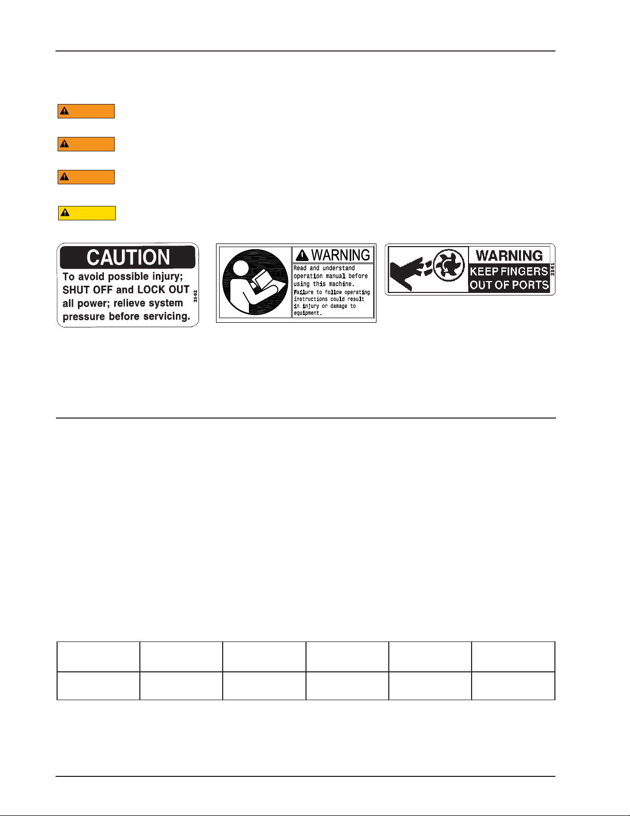
Replacement Label 33-62
Replacement label 33-61
Warnings and Replacement Labels
The Waukesha Cherry-Burrell brand Colloid Mill produces controlled, highly sheared, uniform dispersions and
stable emulsions made up of uniform globules of moderate neness.
A serrated conical stator and a serrated rotating cone make up the emulsifying head.
Operating clearance can be adjusted in .001-inch increments between .010 and .240 inches.
Capacities range from 6.7 to 33.3 gpm (25 to 126 l/m).
Viscosity range is limited only by the maximum 150 psi feed pressure.
Specications
Model
Nominal
Speed Pressure
Nominal
Capacity To
Inlet
Outlet
Nominal
Temp. Range
CM 3600 RPM to 150 psi
(10 bar)
6.7 to 33.3 GPM
(25 to 126 l/m)
2” San. IMDA to 200° (93° C)
WARNING
Stop Machinery to Clean, Service or Repair. To avoid serious injury, do not install or service the
mill unless all power is o and locked out.
WARNING
To avoid electrocution, ALL electrical should be done by a registered Electrician, following
Industry Safety Standards. All power must be OFF and LOCKED OUT.
WARNING
To avoid possible serious injury, shut o and drain product from mill prior to disconnecting the
piping.
CAUTION
Mill parts have sharp edges. To avoid a cutting injury, wear gloves and handle parts carefully.
Replacement Label 121694+
Introduction/Specications
7
95-03028
09/2019
Waukesha Cherry-Burrell®Brand Colloid Mill Introduction/Specications
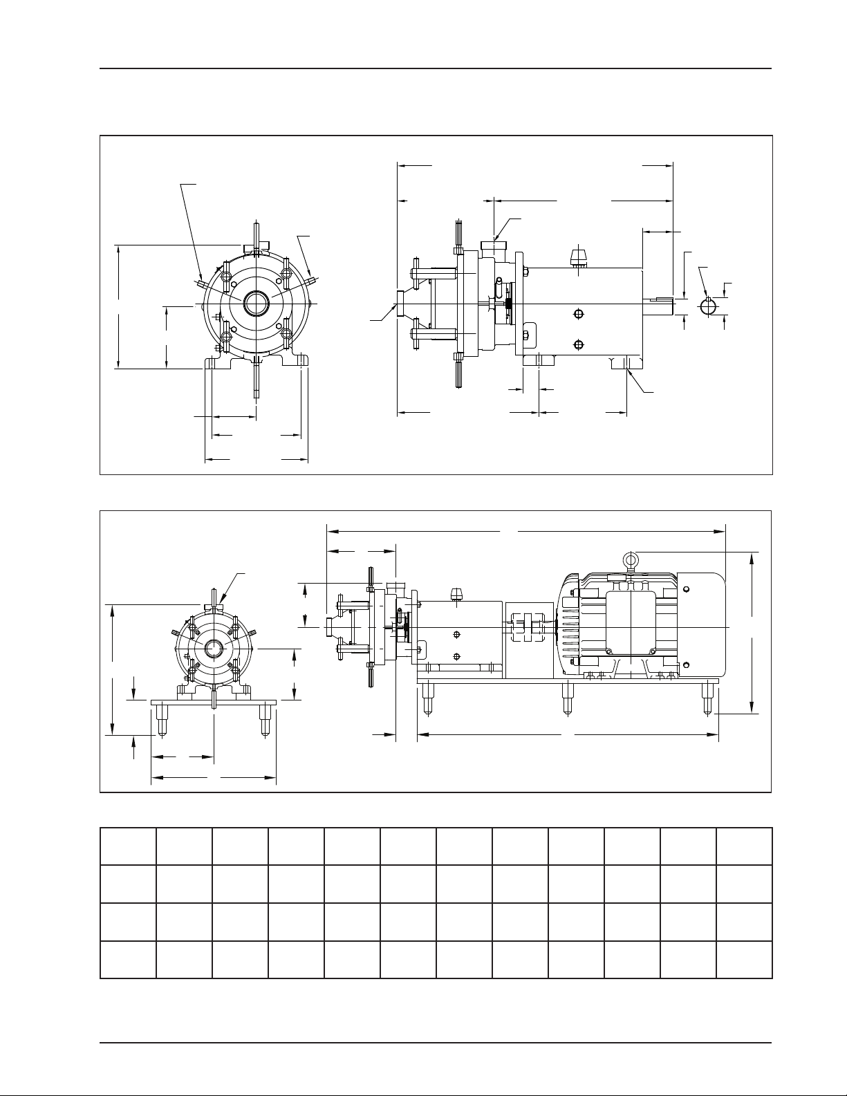
4.31 [110]
8.63 [219]
10.00 [254]
6.00 [152]
12.00 [305]
1.50 [38] TYP.
8.56 [217]
13.75 [349] MIN.
14.88 [378] MAX.
9.38 [238] MIN.
10.51 [267] MAX. 17.44 [443]
26.81 [681] AS SHOWN, WITH STATOR ALL THE WAY IN
27.94 [710] WITH STATOR ALL THE WAY OUT
3.00 [76]
Ø1.50 [38]
1.65
[42]
Ø.56 [14]
.38 KEY [10]
2"-8 IMDA INLET
2"-8 IMDA
OUTLET
1/4-18 NPT PIPE
NIPPLE SEAL
FLUSH OUTLET
1/4-18 NPT PIPE
NIPPLE SEAL
FLUSH INLET
DP100-011
Figure 1
Colloid Mill Unit Dimensions
F
C B
J
X
A
G
2"-8 IMDA
Y
D
T
E
DP100-012
NOTE: The pump is shimmed to “D” height.
Figure 2
Unit
Size A B C D E F G J T X Y
15 HP 51.57
(1310)
41.00
(1041)
2.88
(73)
6.25
(159)
4.75
(121)
8.50
(216)
17.00
(432)
17.69
(449)
17.00
(432)
9.40
(239)
6.00
(152)
20 HP 53.32
(1354)
41.00
(1041)
2.88
(73)
6.25
(159)
4.75
(121)
8.50
(216)
17.00
(432)
17.69
(449)
17.00
(432)
9.40
(239)
6.00
(152)
25 HP 54.20
(1377)
41.00
(1041)
2.88
(73)
7.00
(178)
4.75
(121)
8.50
(216)
17.00
(432)
21.90
(556)
17.00
(432)
9.40
(239)
6.00
(152)
Dimensions shown in IN (mm)
95-03028 09/20198
Waukesha Cherry-Burrell®Brand Colloid MillInstallation and Start-Up
Installation and Start-Up
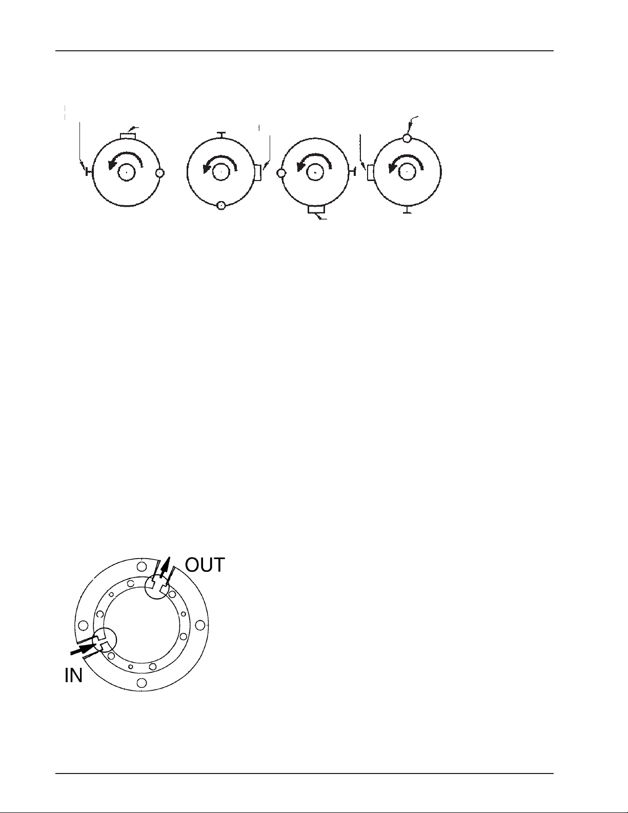
ROTATION
Counter-clockwise
when facing the
outlet port.
See Figure 3. The mill is shipped from the factory with the inlet port as
shown in Position 1. For convenience, the inlet port can be relocated
to any of the other three positions (see Disassembly Procedure). If
Position 4 is used the calibrations at the pointer will be upside down.
We suggest the use of a mirror.
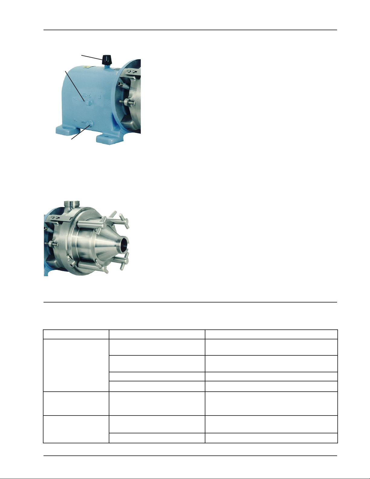
The mill is equipped with a face type seal which must be water
cooled. The IN and OUT ports for introducing the water to the seal
are located in the gland.
NOTE: These are 1/4-inch pipe nipples, but the IN hole is smaller
than the OUT hole to prevent over-pressurizing (Figure 4).
The IN port must be used and the ow of water must be throttled to
produce a ush of 0.125 to 0.25 gpm (0.47 to 0.95 l/m). Flows in
this range provide safe cooling without damage to the lip seal.
Recommendation: use a solenoid valve in the water line to turn on
the water simultaneously with the mill. If the solenoid valve is not
used, turn on the water ush line before starting the mill.
Figure 4
Gland
Figure 3
Indicator
Pointer Knurled Lock Screw
Inlet
Position 1
Outlet Outlet Outlet Outlet
Position 2 Position 3 Position 4
Inlet Inlet
Inlet
Variation of inlet port
Overhead equipment
Wiring
Rotation
Follow accepted engineering practice when connecting the inlet and
outlet with the overhead equipment, piping, or tubing. Use hangers
to eliminate any weight, stress or strain on the mill. Remember, if a
direct connection is made with any overhead tank, install expansion
joints in the line. This will prevent mechanical loads on the mill which
would damage it or aect its operation.
3 Phase, 60 Cycle, 230-460 Volts. Follow the wiring directions on
the motor. Check the direction of rotation.
The rotation direction is counter-clockwise when facing the outlet
port. If run clockwise, the rotor retaining nut may back o, resulting
in damage to the mill.
Seal Flush
9
95-03028
09/2019
Waukesha Cherry-Burrell®Brand Colloid Mill Colloid Mill Troubleshooting
Inlet
Outlet
Figure 6
The mill is shipped with oil in the bearing case. The level should be
checked at the oil level hole and if necessary, oil should be added
through the oil ll hole.
Use Mobil oil DTE BB ISO Grade 220 R & O (Rust inhibited) gear
oil. If DTE BB is not available, use S.A.E. 40 non-detergent mineral
oil. The mill is shipped with a solid cap screw in the oil ll hole. This
should be removed and replaced with the breather cap which is
wired to the mill.
Frequency of lubrication is dependent upon temperature and moisture
conditions. If the room temperature is normal, 70° to 80° F (21° C
to 27° C), and water does not contact the bearing case, change
the oil every 240 operating hours. When the temperature varies
from hot to cold or the mill is ushed out with water, condensation
will occur in the bearing case, requiring more frequent oil changes.
Normal operating temperature of the bearing case is 170° to 190°
F (77° C to 88° C).
Colloid Mill Troubleshooting
Problem Likely Cause Solution(s)
Seals leaking Exceeding 150 PSI pressure
limitation of pump
Open up gap reduce pressure
Seal ush water improperly
plumbed
Connect ush water to IN/OUT ports as
stamped on gland
Water pressure too high Adjust to 0.125 to 0.25 gpm (0.47 to 0.95 l/m)
Seals misaligned on pin Re-align seals to proper t.
Noisy operation /
Excessive power draw
Loose rotor nut causing rotor to
stator contact
Tighten nut to 75 ft-lb.
Check mill rotation (counterclockwise facing
outlet port)
Inconsistent milling
results
Loose adjusting ring Set gap and tighten knurled screw in hole.
Tighten bolt and nut on opposite side.
Worn rotor or stator Replace worn parts
Oil level
Oil drain
Breather cap
Figure 5
Lubrication
The inlet and outlet ports are 2 inch sanitary male threads. The
inlet port is located in the body—its position can be changed. (See
Figure 3 on page 8.) The outlet port is located in the cover of the
mill. The mill must be fed with a pump; a Waukesha Cherry-Burrell
brand positive displacement pump is recommended. The capacity
of the mill is 6.7 to 33.3 gpm (25 to 126 l/m).
Method of feeding and
capacity
95-03028 09/201910
Waukesha Cherry-Burrell®Brand Colloid MillMaintenance
Maintenance
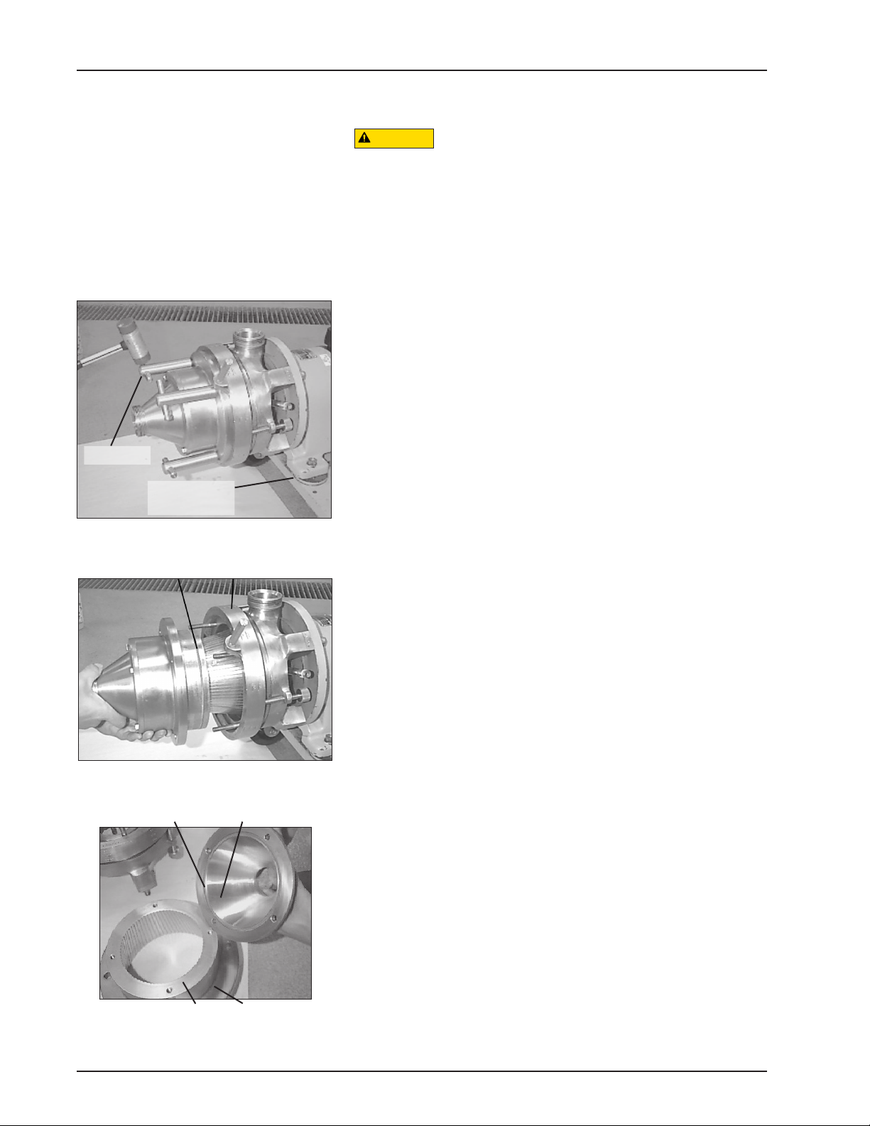
4. Remove the cover capscrews and pull o the cover, then
remove the O-ring.
5. Pull the stator o the studs and remove the O-ring.
In some instances the unit can be cleaned by ushing water through it
while the mill is in operation. However, some of the water will remain
in the bottom of the cone-shaped stator. If this is not acceptable,
dismantle the unit for cleaning.
1. Remove the “T” handles.
2. Back out the knurled lock screw.
CAUTION
Handle all parts carefully to avoid nicks and
scratches which will be detrimental to the operation
of the mill.
Cleaning
O-ring Adjusting ring
Figure 8
Cover
Stator O-ring
O-ring
Figure 9
Figure 7
T-handle
Knurled lock
screw
Flushing
Disassembly
3. Pull the cover/stator assembly outward.
NOTE: You will experience some resistance to the stator
movement due to friction from the O-ring.
As soon as the O-ring is free, the cover and stator assembly can
be easily removed. It is not necessary to remove the adjusting
ring. Disassembly to this point allows complete drainage.
NOTE: To prevent wearing of the faces between the adjusting
ring and stator, lubricate these surfaces occasionally with an
approved silicone-type lubricant.
11
95-03028
09/2019
Waukesha Cherry-Burrell®Brand Colloid Mill Maintenance
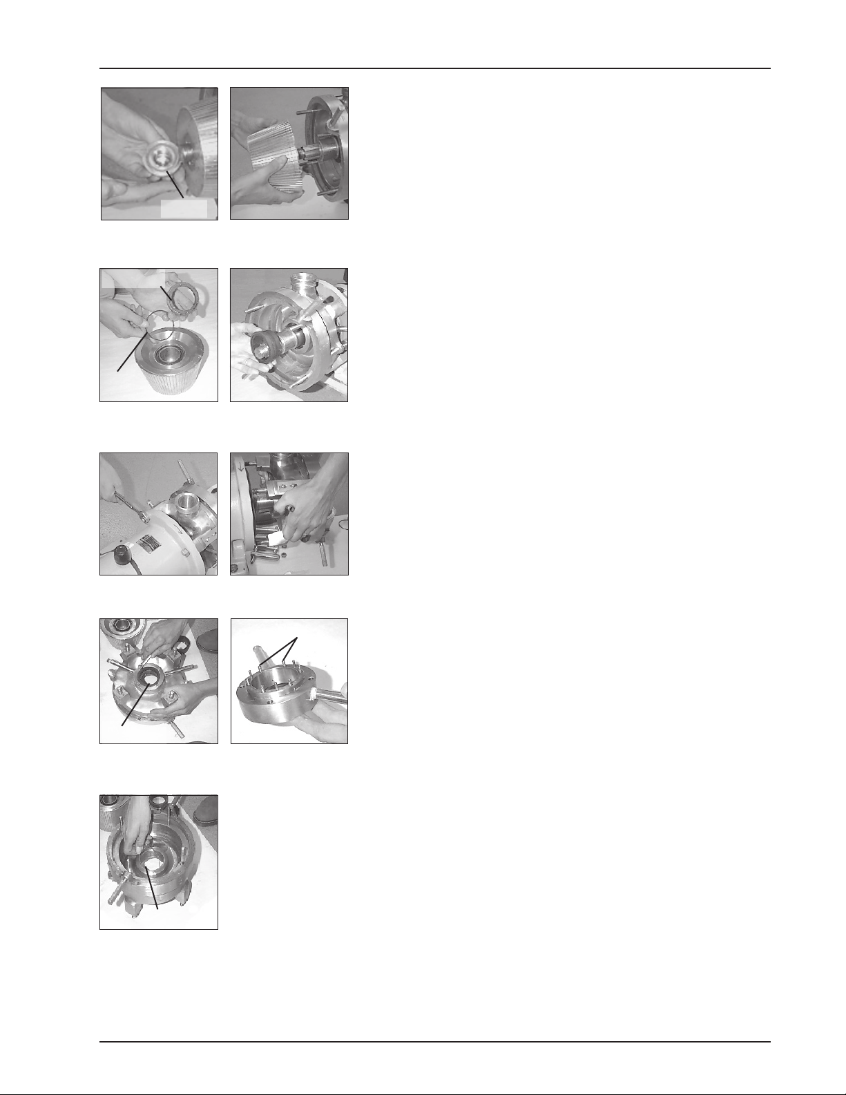
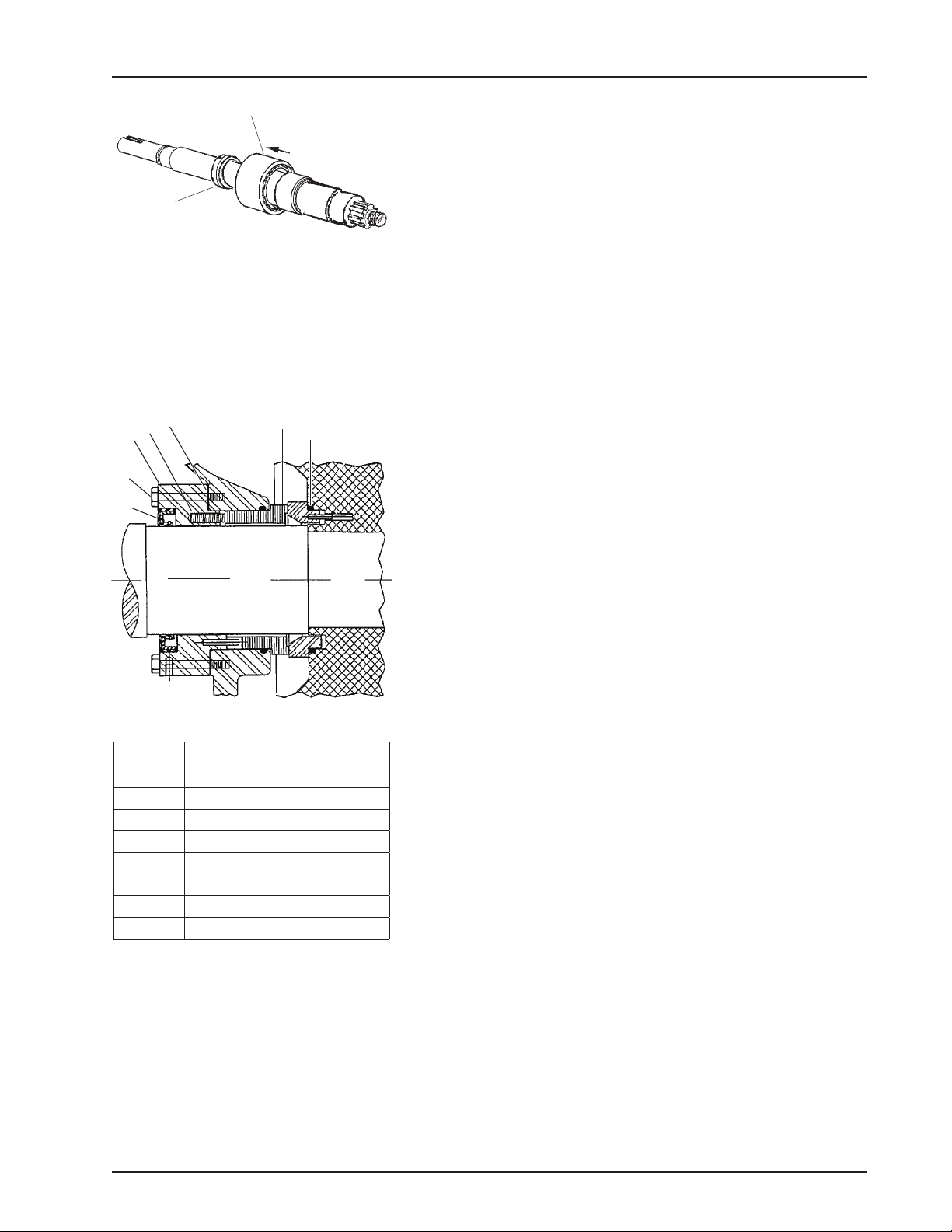
6. Remove the rotor retaining nut, then remove the O-ring from
the nut. (See Figure 10.)
7. Slide the rotor o the shaft, making sure to handle it with care
to avoid damage to the rotor or to the seal seat, which is con-
tained in the rotor. (See Figure 11.)
Figure 13
Figure 10
Springs
Figure 14
Figure 12
Figure 11
Figure 15
Figure 16 Figure 17
Figure 18
O-ring
Lip seal
O-ring
8. Gently pull the seal seat from the back of the rotor and re-
move the O-ring. (See Figure 12.)
9. Remove the seal assembly from the shaft. (See Figure 13.)
10. Remove the four 1/2-13 hex nuts which secure the body to
the bearing case and slide the body forward o the shaft. (See
Figure 14 and Figure 15.)
O-ring
Seal seat
11. Remove the four capscrews from the gland on the back side
of the body and disassemble the gland.
NOTE: There are six loose springs in the gland.
The gland lip seal can be pressed out if replacement is re-
quired. (See Figure 16 and Figure 17.)
12. Remove the O-ring from inside the body. Use the O-ring
removal tool (part no. AD0096001) if necessary. (See Figure
18.)
NOTE: Clean and inspect all parts thoroughly. DO NOT reuse
the seal or seal seat if it is scratched, chipped or worn.

95-03028 09/201912
Waukesha Cherry-Burrell®Brand Colloid MillMaintenance
Small (1/8”) hole
(IN)
Figure 19 - Water ush system
Locking holes
Knurled
locking screw
Figure 20
Stator
Adjusting ring
T-handles
Indicator
Lock bolt
Figure 21
Large (1/4”) hole
(OUT)
Flushing backwards can cause seal leakage and
ush media will enter the product zone.
CAUTION
1. Apply a suitable lubricant to all O-rings and insert them in their
respective grooves.
NOTE: Place the seal seat O-ring over the seal seat and then
insert the seat into the rotor.
2. Follow the disassembly procedure in reverse order to com-
plete assembly. Torque the rotor nut to approximately 75 ft-lb
(102 N·m).
3. The seal water to the mill must be connected to the gland
connection marked IN (the ports are stamped “IN” and
“OUT”). The inlet of the gland contains the smaller (1/8”) hole.
The outlet contains the larger (1/4” hole). (See Figure 19).
The mill can be adjusted to have a clearance between the rotor and
the stator from a minimum of 0.010” (0.254 mm) to a maximum of
0.240” (6.1 mm), in increments of 0.001” (0.025 mm).
The body and the adjusting ring are calibrated as a unit and serialized;
they must not be interchanged with other Waukesha Cherry-Burrell
brand Colloid Mills.
The stator is held rmly against the adjusting ring by “T” handles
(Figure 21).
Adjust the clearance between the rotor and stator by turning the
adjusting ring counter-clockwise (when facing the outlet port) to
increase the clearance, and clockwise to decrease the clearance.
The adjusting ring is engraved with numerals indicating the clearance
in increments of 0.010” (0.254 mm). The indicator pointer indicates
the desired clearance. For setting in between the increments of
0.010” (0.254 mm), the drill point spacing is equal to 0.001” (0.025
mm) clearance. The drill point spacing coincides with the locking
hole spacing. There are 18 locking holes in the ring, spaced 20°
apart (Figure 20).
Rotating the ring by 20° (hole to hole distance) changes the milling
clearance by 0.001” (0.025 mm).
Example: to obtain 0.014” radial clearance, locate the 0.010 punch
mark under the pointer. Turn the ring counterclockwise four additional
drill points (or locking holes), and lock it in place with the knurled lock
screw (Figure 20). Tighten the “T” handles to rmly hold the stator
against the adjusting ring. The clearance will be 0.014” (0.36 mm).
Adjust the lock bolt and tighten the nut (Figure 21).
Assembly
Adjustment and
Calibration
13
95-03028
09/2019
Waukesha Cherry-Burrell®Brand Colloid Mill Maintenance
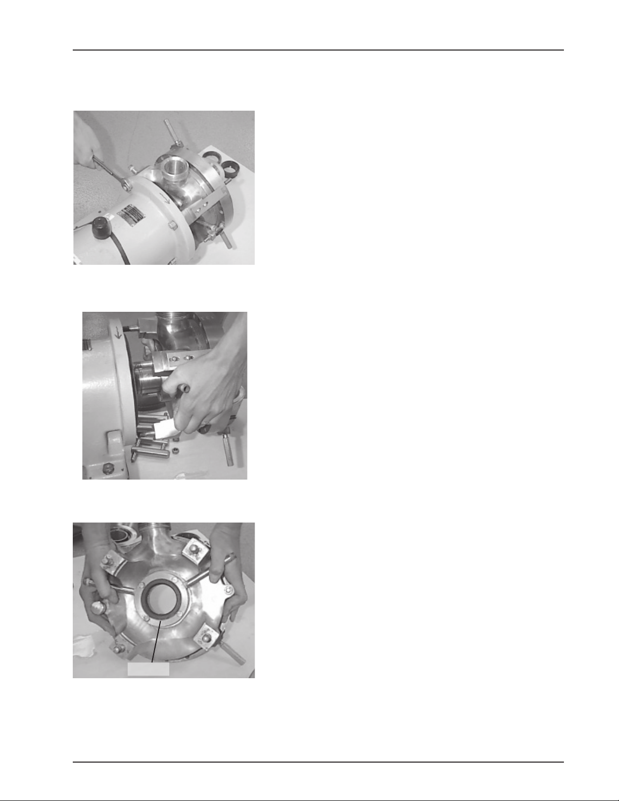
1. Disassemble as described in “Disassembly” on page 10.
2. Remove the four body nuts (Figure 22).
3. Slide the body forward o the shaft (Figure 23).
4. Pull the seal out with a hook tool. Insert a new water lip seal
with the lip facing in. (See item 18 in Figure 29 on page 15.)
5. Re-assemble in reverse order.
Flush Water Seal
Replacement
Figure 22 - Remove body nuts (4)
Figure 23 - Remove body
Figure 24 - Replace lip seal
Lip seal

95-03028 09/201914
Waukesha Cherry-Burrell®Brand Colloid MillMaintenance
Tools required for seal and/or bearing replacement:
• Assorted hand tools including soft hammer.
• Bearing puller or press.
• Hook tool for seal removal.
• Spanner wrench for bearing retainer nut removal
• Rotor Nut Wrench part no. GD0019000
• Anti-seize compound and seal lubricating grease.
• 2 quarts DTE BB Mobil oil or equivalent.
Service Preparation
1. Shut OFF and lock out all power.
2. Remove all product and ushing from the mill.
3. Disconnect all piping to the mill.
4. Remove the pump anchor screws and slide the gearcase o
the motor coupling.
5. Place the mill on a sturdy work surface.
6. Disassemble the wet end of the mill completely. (See “Disas-
sembly” on page 10.)
7. Drain the oil from the gear case (Figure 25).
Front Seal Replacement
1. See Figure 26. Pull o the slinger.
2. Remove the four capscrews, then remove the bearing retainer
assembly (front seal inside).
3. Note the seal lip position and knock out the old seal
4. Place lubrication around the new seal and press it into the
bearing retainer. Replace the gasket, if necessary. Lubricate
the seal lip and install the bearing retainer and slinger.
Rear Seal Replacement
1. See Figure 27. Pull the rear oil seal o the drive shaft with a
hooked tool.
2. Place tape over the shaft keyway and install a new seal. (Lu-
bricate the seal lip before sliding it onto the shaft.)
Bearing Replacement
1. Remove the rear seal. Remove the rear bearing retaining ring.
Press the drive shaft out through the front of the gear case
(through the rear bearing) (Figure 27).
2. Remove the bearing locknut from the shaft (counter-clock-
wise) and press o the front bearing (Figure 26).
3. Press the rear bearing out of the front of the gear case (Figure
27).
Gear Case Service
CAUTION
To avoid a cutting injury, wear gloves and handle
parts carefully.
Figure 25
Oil level
Breather cap
Oil drain
Figure 26
Bearing retainer
assembly
Gasket
Front seal
Slinger
Figure 27
Rear seal
Retaining
ring Rear
bearing
15
95-03028
09/2019
Waukesha Cherry-Burrell®Brand Colloid Mill Maintenance
NOTE: Use care at all times to avoid chipping or scratching the seal
or seat. Keep the seal face areas clean and dry.
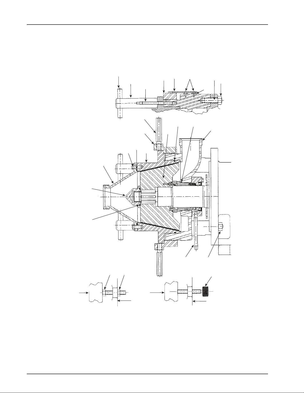
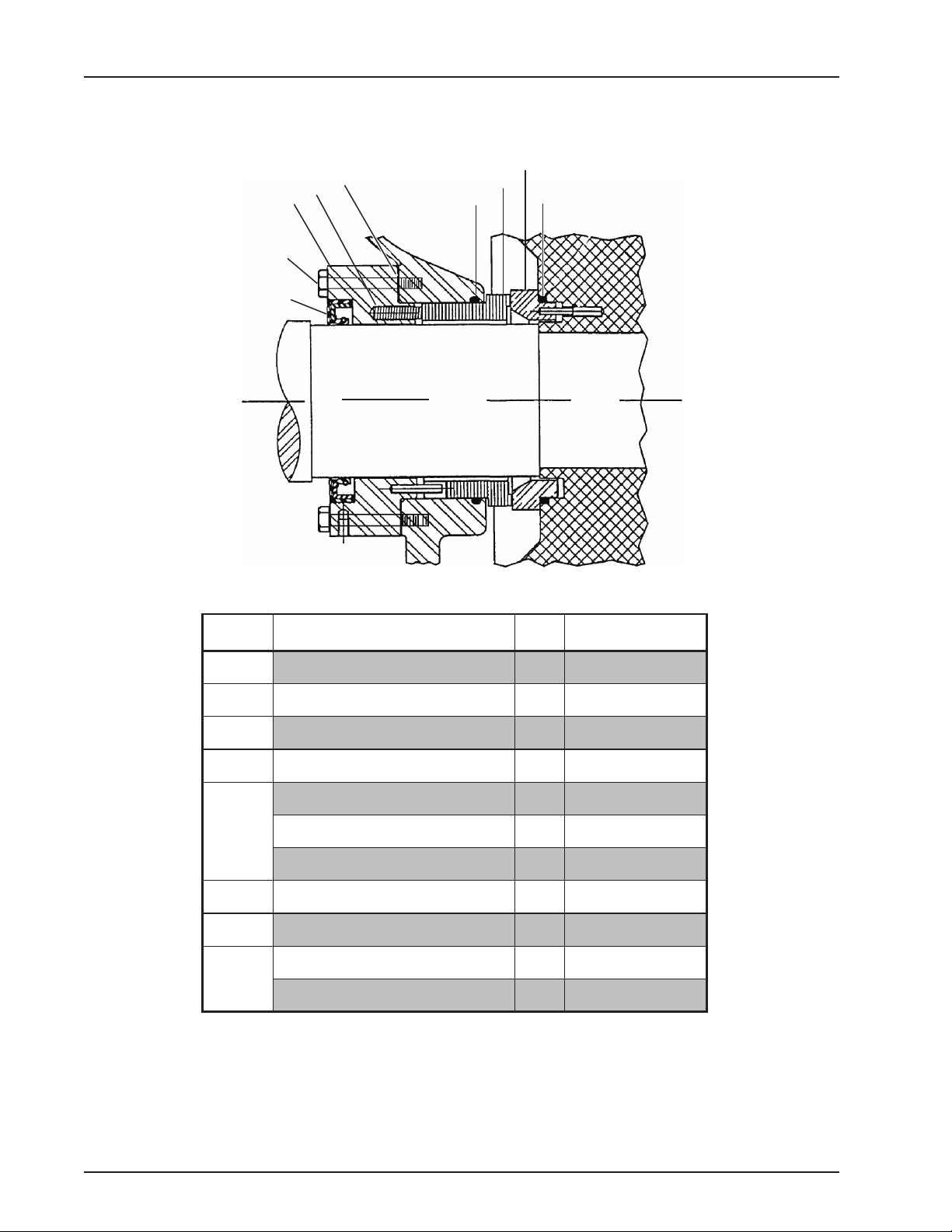
1. See Figure 29. Install the gland plate lip seal (18) into the rear
of the gland plate (17).
2. Apply a small amount of sealant to one end of each of the six
springs (19) and place them in the gland spring holes (17).
3. Install the gasket (16) to the sealing face of the gland plate
(17).
4. Attach the gland plate (17) to the mill body using the existing
capscrews.
5. Install one O-ring (24) into the groove in the mill body.
6. Attach the body to the bearing case (using 4 nuts).
7. Lubricate the O-ring (24) and small O.D. of the seal (20) with
a compatible lubricant. Install the seal into the mill, aligning
the notches on the seal with the pins in the gland plate.
NOTE: Avoid grease-type lubricants which can harden and bind
the seal; use food-grade lubricant when processing food products.
8. Lubricate the remaining O-ring (24) with a compatible lubri-
cant and install it on the small O.D. of the seat (21).
9. Install the seat (21) (with pins and O-ring) into the rear of the
rotor, aligning the pins with the holes in the rotor.
10. Install the rotor onto the shaft, being careful to avoid damage
to the seat (21) or seal (20). Tighten the rotor nut to 75 ft-lb
(102 N·m).
11. Complete the mill assembly. (Reverse steps 2 and 3 on page
13.)
Sanitary Seal Replacement
DP100-004
18
22
17
19 16
24
20
21
24
Figure 29
Item No. Description
16 Gland Gasket
17 Gland Plate
18 Gland Plate Lip Seal
19 Spring
20 Stationary Seal
21 Rotating Seat
22 Capscrew
24 Seal Seat & Body O-ring
NOTE: See page 20 for part numbers.
4. Clean and lubricate all parts thoroughly before reassembling.
NOTE: Do not unwrap the new bearings until ready to install.
5. Lubricate the inner races and press the new bearings onto the
shaft. Tighten the locknut on the front bearing to 40 ft-lb (54
N·m) (Figure 28).
6. Lubricate the outer races and press the shaft assembly into
the case. Replace the retaining ring and rear seal (Figure 24).
7. Replace the mill assemblies.Torque the rotor nut to 75 ft-lb
(102 N·m). Rell the crankcase with 2 quarts of Mobil DTE BB
oil.
Figure 28
Front bearing
Locknut

95-03028 09/201916
Waukesha Cherry-Burrell®Brand Colloid MillMaintenance
DP100-003
14
15 1
65432
11
13
7
8912
10
Colloid Mill Gear Case
52
51
48,
49
50,
49
DP100-005a
Parts List
52

17
95-03028
09/2019
Waukesha Cherry-Burrell®Brand Colloid Mill Maintenance
ITEM NO. DESCRIPTION QTY PART NO. NOTES
1Gear Case 1 0MS005000
2Drive Shaft 1 0MS008000
3Front Bearing 1 0MS036300
4Bearing Locknut 1 0MS036N00
5Rear Bearing 1 0MS036000
6Retaining Ring 1 BD0087R00
7Front Bearing Retainer Gasket 1 0MS042B00
8Front Bearing Retainer 1 0MS080000
9Pump End Shaft Seal 1 0MS030100
10 Capscrew 4 30-274
11 Drive End Shaft Seal 1 0MS030000
12 Slinger 1 0MS045000
13 Breather 1 139779+
14 Level Indicator 1 115799+
15 Drain Plug 1 115798+
48 Nameplate, Sanitary 1 001061002
49 RHDS 6 30-355
50 Caution Label, Yellow 1 33-62
51 Key 1 000037003
52 Rotor Nut Wrench 1 CD0019001
PL5081-CH12
Colloid Mill Gear Case
95-03028 09/201918
Waukesha Cherry-Burrell®Brand Colloid MillMaintenance
DP100-005
39
38 37
30 44
46,
47
45
28 29
30
23
26 25
30
27
23
2943
32
34
40
42 41 35
30
31
33
36 24 23
Colloid Mill Fluid Head
NOTE:
Torque rotor nuts
to 75 ft-lb
Used to set adjusting
ring at minimum
setting of 0.010”
Used to hold
adjusting ring
setting
NOTE:
Body rotor
clearance starts
at 0.101” and
ends at 0.220”
in increments of
0.010”

19
95-03028
09/2019
Waukesha Cherry-Burrell®Brand Colloid Mill Maintenance
ITEM NO. DESCRIPTION QTY PART NO. NOTES
23 Body, 2” Bevel Seat 1 0MS001000
Body, 2” TCF 1 35886+
24 Seal Seat & Body O-ring, FKM 2 V70150
Seal Seat & Body O-ring, Silicone 2 S75150
25 Hex Nut 1 36-55
26 Capscrew 1 30-86
27 Knurled Lock Screw 1 0MS129000
28 Stud - Body 4 0MS011000
29 Hex Nut 4 36-70
30 Adjusting Ring 1 0MS003000
31 Adjusting Ring Handle 2 0MS054000
32 O-ring, Rotor Nut, FKM 1 V70222
O-ring, Rotor Nut, Silicone 1 S75222
33 Rotor 1 0MS010000
34 Rotor Retaining Nut 1 0MS052000
35 Stator 1 0MS004000
36 O-ring, Stator, FKM 1 V70263
O-ring, Stator, Silicone 1 S75263
37 Stud, Handle Shaft 4 0MS011100
38 Handle Shaft 4 0MS099000
39 Handle Pin 4 0MS100000
40 Cover, 2” Bevel Seat 1 0MS002000
Cover, 2” TCF 1 35887+
41 O-ring, Cover, FKM 1 V70253
O-ring, Cover, Silicone 1 S75253
42 Capscrew 4 30-151
43 Pipe Nipple 2 0MS018000
44 Indicator 1 0MS056100
45 Spacer 2 0MS454000
46 Machine Screw 2 30-299
47 Lockwasher, #10 2 43-21
PL5081-CH13
Colloid Mill Fluid Head
95-03028 09/201920
Waukesha Cherry-Burrell®Brand Colloid MillMaintenance
DP100-004
18
22
17
19 16
24
20
21
24
KIT # 35379+ Convert single spring seal to multiple spring seal
Sanitary Seal
Item No. Description Qty Part No.
16 Gland Gasket 1 0MS042G00
17 Gland Plate 1 0MS058200
18 Gland Plate Lip Seal 1 0MS030200
19 Spring 6 0MS304200
20
Stationary Seal, Carbon 1 0MS306003
Stationary Seal, Silicon Graphite 1 0MS306004
Stationary Seal, Silicon Carbide 1 0MS306009
21 Rotating Seat, Silicon Graphite 1 0MS014002
22 Capscrew 4 30-98
24
Seal Seat & Body O-ring, FKM 2 V70150
Seal Seat & Body O-ring, Silicone 2 S75150
PL5081-CH11
This manual suits for next models
1
Table of contents


