SPX Power Xpress User manual

Power Xpress™
Bollard Charge Station
Installation Guide

2
Power Xpress™ Bollard Charge Station
Installation Guide
EL-50600-17 Rev. A
Technical Support
1-877-805-EVSE (3873)
Copyright © 2012 Service Solutions U.S. LLC
All rights reserved.
The information, specications, and illustrations in this guide are based on the latest
information available at the time of printing. Service Solutions U.S. LLC reserves the right to
make changes at any time, without notice.

3
Power Xpress™ Bollard Charge Station
Installation Guide
EL-50600-17 Rev. A
TABLE OF CONTENTS
INSTALLATION SAFETY..................................................................................................4
INSTALLATION CONTENTS: BOLLARD AND EVSE (EL-50650) ...........................................5
Power Xpress EVSE (EL-50600-300) for Bollard Charge Station ....................................5
Bollard and Hardware (EL-50600-500) .......................................................................5
TOOLS SUGGESTED FOR INSTALLATION (NOT PROVIDED)..............................................6
APPLICABLE ELECTRICAL SYSTEMS................................................................................7
220/240V Single Phase (North America).....................................................................7
208V 3-Phase Wye Connection (North America)..........................................................7
240V 3-Phase Delta Connection (North America) with Center Tap on One Leg ..............8
230V Above Ground (Europe)
230V Single Phase....................................................................................................9
ELECTRICAL REQUIREMENTS FOR BATTERY CHARGING................................................10
AMPERAGE AND BREAKER PARAMETERS ......................................................................11
STANDARD INSTALLATION ..........................................................................................13
EVSE POWER AND STATUS LED INDICATIONS ..............................................................22
TROUBLESHOOTING ...................................................................................................23
Ground Fault Circuit Interrupt (GFCI) Tripped ...........................................................24
Missing Ground ......................................................................................................24
LIMITED WARRANTY ...................................................................................................25

4
Power Xpress™ Bollard Charge Station
Installation Guide
EL-50600-17 Rev. A
INSTALLATION SAFETY
SAVE THESE IMPORTANT SAFETY INSTRUCTIONS.
This guide contains important instructions that must be followed during the installation of the electric ve-
hicle supply equipment (EVSE). All instructions should be carefully read before installation of the EVSE.
WARNING: Turn OFF the circuit breaker
at the service or distribution panel before
performing any electrical work or repairs.
WARNING: The EVSE should be installed by
a licensed electrician in accordance with all
local electrical codes, ordinances, and all
authorities having jurisdiction.
WARNING: Do not install the EVSE near
ammable, explosive, or combustible
materials. Do not locate or store ammable,
explosive, or combustible materials near the
EVSE.
WARNING: Improper installation of the
EVSE can result in personal injury or
product damage.
WARNING: This EVSE installation guide
is not a substitute for electrical safety
precautions.
WARNING: Use this EVSE within the
specied operating parameters. Failure to
do so may result in injury or death.
WARNING: Locate and install this EVSE in
a location where the charge cable will not
be stepped on, tripped over, or subject to
damage or stress.
WARNING: The EVSE must be connected to a
grounded, metal, permanent wiring system,
or an equipment-grounding conductor
must be run with the circuit conductors
and connected to the equipment grounding
terminal on the EVSE.
CAUTION: Incorrect installation of the EVSE
can result in damage to the vehicle’s battery
and to the EVSE itself. These damages will void
the warranty for the vehicle and the EVSE.
CAUTION: Do not operate the EVSE in
temperatures beyond its operating range of
-40°F to +122°F (-40°C to +50°C).

5
Power Xpress™ Bollard Charge Station
Installation Guide
EL-50600-17 Rev. A
INSTALLATION CONTENTS: BOLLARD AND EVSE (EL-50650)
Power Xpress EVSE (EL-50600-300) for Bollard Charge Station
1
EVSE (including attached cable with strain
relief and grommet, input/output decals, ag
tag, and vehicle coupler)
POWER
STATUS
RESET
1 Decal and cover kit
1-877-805-EVSE (3873)
http://evse.spx.com
1 Cable-management hook
1 Power Xpress Bollard Charge Station Installation Guide
1 Power Xpress EVSE User Manual
Bollard and Hardware (EL-50600-500)
1Bollard (including upper and lower plastic
covers)
2Cable-management retaining screws (pre-
installed)
1Locating set screw (plastic bag attached to bol-
lard)
6
Power Xpress™ Bollard Charge Station
Installation Guide
EL-50600-17 Rev. A
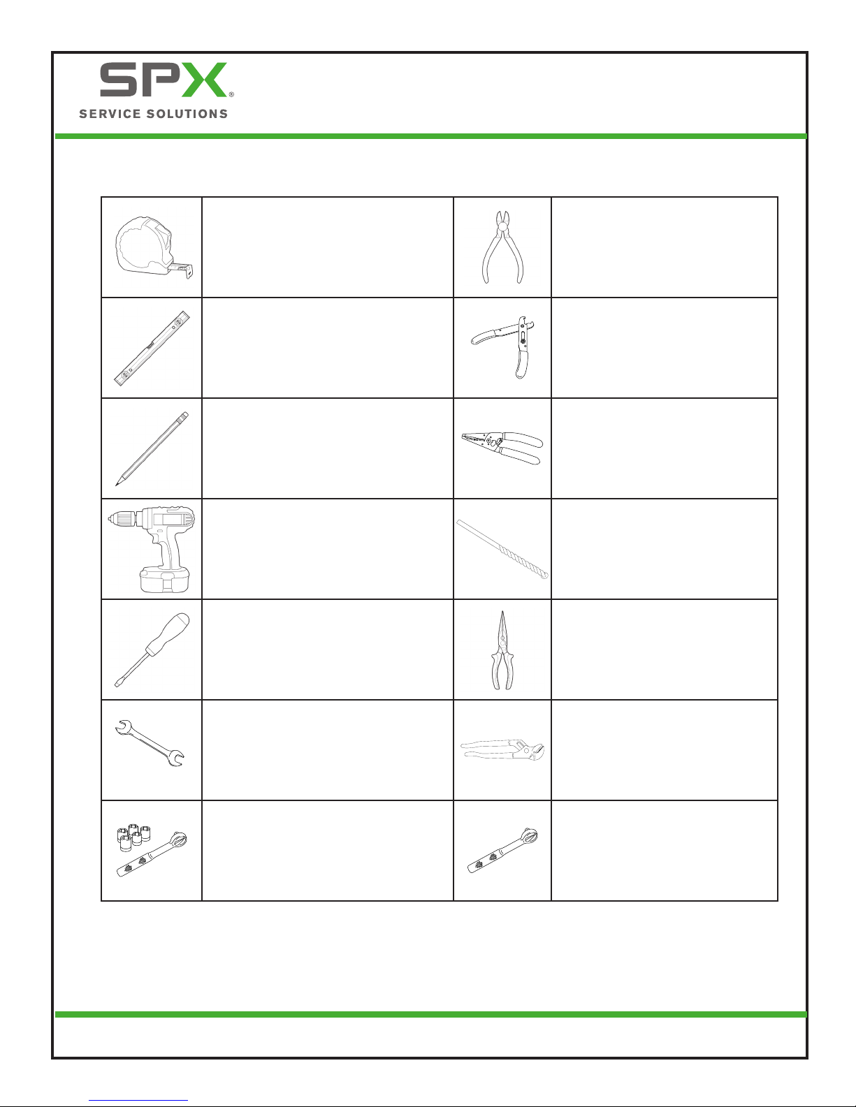
TOOLS SUGGESTED FOR INSTALLATION (NOT PROVIDED)
Tape measure Wire cutters
2-ft Level Wire stripper
Pencil Nonmetallic wire stripper
Power hammer drill Masonry drill bit set
Small at-blade screwdriver Needle-nose pliers
7/16in
7/16-in. Open-end wrench Expandable pliers
1/2-in. Ratchet and sockets Torque wrench
7
Power Xpress™ Bollard Charge Station
Installation Guide
EL-50600-17 Rev. A
APPLICABLE ELECTRICAL SYSTEMS
IMPORTANT: The on-site service connection must
be properly identied before installation of the
EVSE. If you are unsure of the available service
connection, consult the local utility company or
contact Service Solutions US at 1-877-805-EVSE
(3873).
NOTE: The L1, L2, and ground outputs (H, N for
Europe) in the following illustrations corre-
spond to the inputs on the EVSE.
NOTE: For the (earth) ground connection, always
connect the neutral at the service panel to
earth ground. Ground fault protection is not
possible unless the neutral (center tap on
the service transformer) is connected to an
earth ground.
220/240V Single Phase (North America)
NEUTRAL
(NOT USED)
120V
120V
L2
L1
240V
Figure 1. 220/240V Single Phase
WARNING: The EVSE is a single-phase
device. Do not connect all three phases
of a 3-phase feed. Only three wires are
connected, take care that the service
transformer secondary connection is
known, and the three wires from the
main-panel circuit breaker are correctly
connected and labeled.
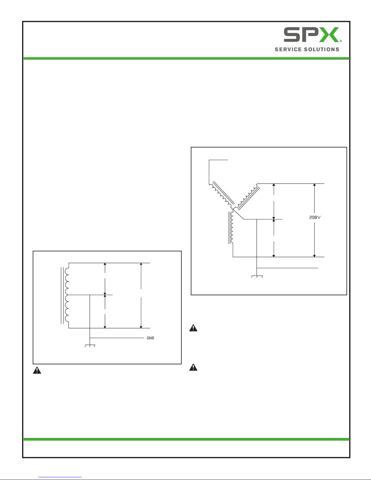
208V 3-Phase Wye Connection (North
America)
Any two of the legs can be used to provide 208V to the
EVSE with a Wye-connected secondary. For example,
L1 and L2, or L1 and L3, or L2 and L3. Reference the
wiring diagram below.
L3 (NOT USED)
120V
NEUTRAL
(NOT USED)
120V
L1
L2
GND
Figure 2. 208V 3-Phase Wye Connection
NOTE: A current-carrying neutral is not required for the
EVSE for 208V connections.
WARNING: The EVSE must be installed by a
licensed electrician and in accordance with
all local electrical codes, ordinances, and all
authorities having jurisdiction.
WARNING: Do not install the EVSE near
ammable, explosive, or combustible
materials. Do not locate or store ammable,
explosive, or combustible materials near the
EVSE.

8
Power Xpress™ Bollard Charge Station
Installation Guide
EL-50600-17 Rev. A
NOTE: The third line (L3 on the illustration of the
delta) is 208V, with respect to the neutral,
and is sometimes referred to as a “stinger.”
WARNING: Do not use this third line.
NOTE: The two used phases must each measure
120V to neutral or ground.
NOTE: Consult the utility company or the trans-
former manufacturer’s literature to verify
that the single leg can supply the required
power.
NOTE: The EVSE will only operate properly if it de-
tects the presence of a ground wire con-
nected to a neutral point on the transformer
secondary.
WARNING: Do not use a 3-phase delta-
connected transformer secondary
without a center tap on one leg and/or
without a neutral point available for the
required ground connection.
240V 3-Phase Delta Connection (North
America) with Center Tap on One Leg
One leg must be center-tapped, and only the two
phases on either side of the center tap can be used
with the delta connection.
L3 (NOT USED)
L1
CENTER TAP
L2
120V
120V
NEUTRAL
(NOT USED)
L1
240V
L2
GND
Figure 3. 240V 3-Phase Delta Connection
9
Power Xpress™ Bollard Charge Station
Installation Guide
EL-50600-17 Rev. A
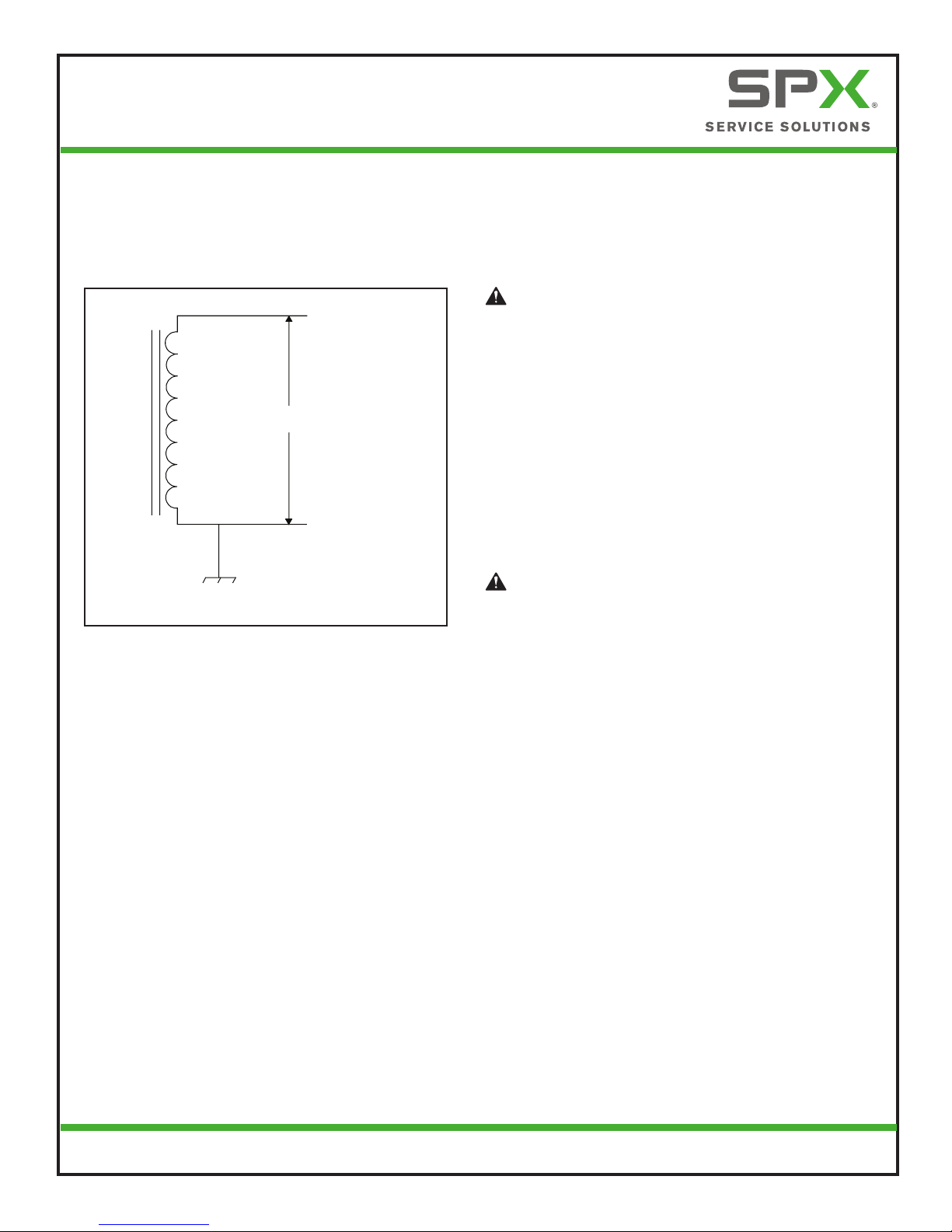
230V Above Ground (Europe)
230V Single Phase
LINE (H)
230VAC
NEUTRAL (N)
EARTH
Figure 4. 230V Single Phase
WARNING: The EVSE is a single-phase
device. When connecting the line and
neutral wires, take care that the service
transformer secondary connection is
known, and the wires from the main
circuit breaker panel are correctly
connected and labeled. The following
service connections are primarily used in
Europe and Australia (sometimes known
as “TT Power Grid”). Please reference
the following diagram. The line, neutral,
and earth outputs on the illustration
correspond to the inputs on the EVSE.
WARNING: The line connection must
measure 230V RMS to neutral. Earth must
also be connected to the EVSE.

10
Power Xpress™ Bollard Charge Station
Installation Guide
EL-50600-17 Rev. A
CAUTION: The AC electrical connection must
have a grounded, dedicated service-main. No
other loads shall be connected to the same
circuit. Use of a non-dedicated circuit could
exceed the current rating of the circuit breaker
and cause it to trip or open.
6 in.
18 in.
24 in.
G
F
B
AH
C
D
E
A. Conduit extending up to 24 in. (61 cm) from
ground level or per local code
B. Conduit sweep
C. THWN rigid-metal, Schedule 40 or 80 conduit
D. THWN nonmetallic, Schedule 40 or 80 conduit
E. UF burial wire (ground solid)
F. Ground level
G. Service panel
H. Minimum wire length of 66 in. (168 cm)
Figure 5. Wire Run Variations
WARNING: The EVSE must be installed
by a licensed electrician in accordance
with all national and local electrical codes,
ordinances, requirements and all authorities
having jurisdiction.
The conduit may extend up to 24 in. (61 cm) from
ground level. The wiring should extend 66 in. from
the base mounting of the bollard. A sweep is used to
direct the circuit from the conduit to the electric circuit
from the service panel. The three types of acceptable
wire runs are:
• THWN rigid metal Schedule 40 or 80 conduit,
buried 6 in. (15 cm) below ground level, or per
local electrical code.
• THWN nonmetallic Schedule 40 or 80 conduit,
buried 18 in. (46 cm) below ground level, or
per local electrical code.
• UF burial wire (ground solid), buried 24 in. (61
cm) below ground level, or per local electrical
code.
• THHN, THWN, or THWN-2 wires are recom-
mended to allow for proper space requirements
inside the 1/2 in. exible conduit required in-
side the bollard.
ELECTRICAL REQUIREMENTS FOR BATTERY CHARGING
11
Power Xpress™ Bollard Charge Station
Installation Guide
EL-50600-17 Rev. A
AMPERAGE AND BREAKER PARAMETERS: FIELD REQUIREMENTS AND
ADJUSTMENTS FOR EVSE INSTALLATION (NOT REQUIRED FOR 40 AMP
CIRCUIT INSTALLATION)
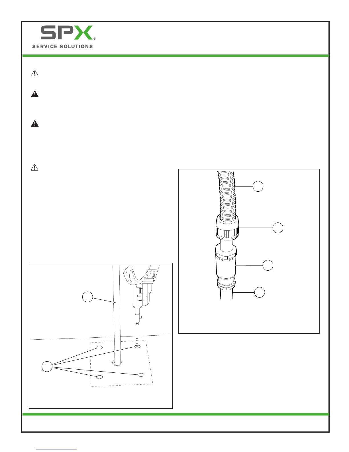
1. Unpack the EVSE.
A
B
D
C
A. EVSE body
B. EVSE cable
C. Strain relief with grommet
D. 18 in. (46 cm)
Figure 6. EVSE
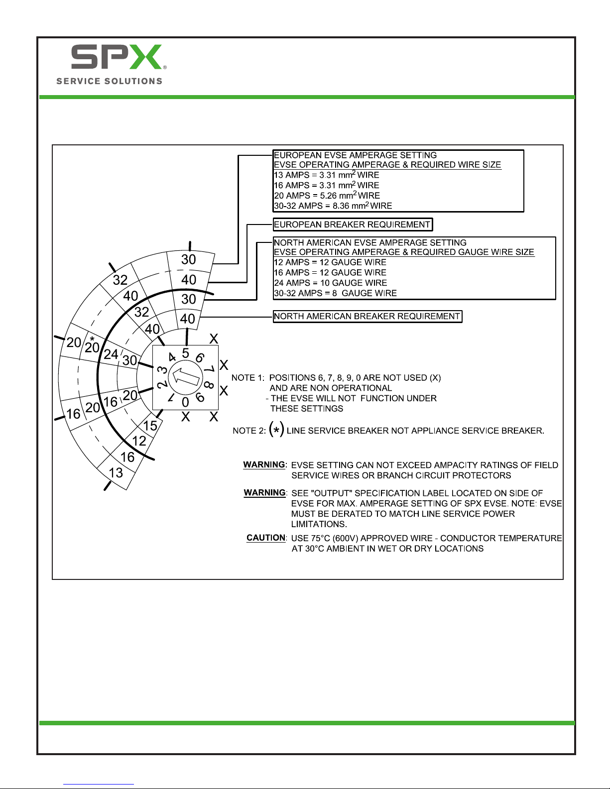
NOTE: The EVSE has been factory set at 30 amp
output for a 40 amp circuit. Proceed to
“Standard Installation” if installing on a 40
amp circuit. For all other amperages, com-
plete Steps 2 and 3 for EVSE adjustment.
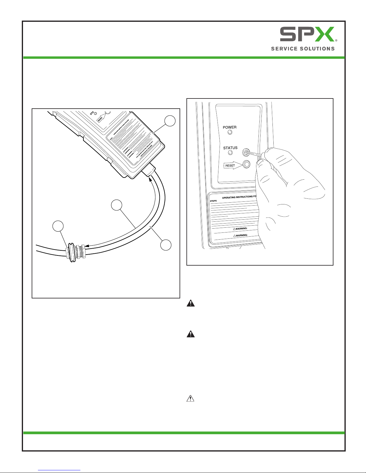
2. Remove the domed cap from the current-
adjustment selector (positioned just above the
reset button on the front of the EVSE).
3. Using a small, at-blade screwdriver, set the
current-adjustment selector to the applicable
output current-limiting setting as specied in
“Figure 8. Current-Adjustment Settings”.
Figure 7. Setting the
Current-Adjustment Selector
NOTE: Positions 6, 7, 8, 9, 0 are not used (X) and
are non-operational. The EVSE will not
function under these settings.
WARNING: The EVSE setting cannot
exceed ampacity ratings of eld service
wires or branch circuit protectors.
WARNING: See “output” specication
label located on the side of the EVSE
for maximum amperage setting, per
limitations of vehicle cable and coupler.
NOTE: The EVSE must be de-rated to match line
service power limitations.
CAUTION: Use 75°C (600V) approved wire,
conductor temperature at 30°C ambient in wet
or dry locations.
12
Power Xpress™ Bollard Charge Station
Installation Guide
EL-50600-17 Rev. A
Figure 8. Current-Adjustment Settings

13
Power Xpress™ Bollard Charge Station
Installation Guide
EL-50600-17 Rev. A
STANDARD INSTALLATION
1. Lay down the bollard box and remove the
banding.
2. Lift the top off the box and remove the bollard
from the packaging material.
3. Remove the upper cover from the bollard
assembly by removing the cable-management
retaining screws (E) on the rear of the bollard.
4. Remove plastic bag containing locating set
screw (not shown) from inside bollard.
A
B
C
D
E
A. Upper plastic cover
B. Metal Bollard
C. Lower plastic cover (Do not remove)
D. Seal
E. Cable-management retaining screws
Figure 9. Bollard Disassembly
NOTE: The upper and lower plastic bollard covers
are a matched set and cannot be used inter-
changeably with those from other bollards.
The standard installation design for the Power
Xpress Bollard is a bolt-down external plate.
The standard diameter of the bollard is approxi-
mately 7 in. The bollard height will vary with the
application.
Figure 10. Typical Installation
10 in.
7½ in.
15/16 in.
10 in.
7½ in.
Figure 11. Base Plate Dimensions
14
Power Xpress™ Bollard Charge Station
Installation Guide
EL-50600-17 Rev. A
CAUTION: Read all instructions before installing
the EVSE.
WARNING: Main service power must be
off and disconnected before attempting
to install the EVSE.
WARNING: The bollard weighs 20 lb per
foot, and the bottom end is signicantly
heavier than the top end. Take proper
precautions and use safe lifting practices
when lifting the bollard.
CAUTION: All adapter and connection ttings
must be classied as liquid-tight. The following
types of exible conduit are recommended:
LFMC (liquid-tight exible metal conduit),
LFNC-B (liquid-tight exible nonmetal conduit),
or LFNC-A (liquid-tight fexible nonmetal
conduit).
1. Place the bollard where it is to be installed and
drill holes.
2. Install the 3/4 in. anchor bolts in accordance
with industry standards for the type of
mounting being performed.
A
B
A. Conduit stand pipe
B. Marked locations for anchor bolts
Figure 12. Drill Holes
NOTE: Depending on the type and size of the con-
duit stand pipe, a variety of adapters may
be used to convert the stand pipe to 1/2-in.
liquid-tight exible conduit.
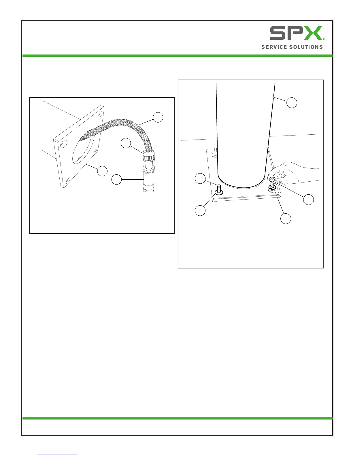
3. Slide the wires through the required adapters
and the 1/2-in. liquid-tight exible conduit.
4. Install 1/2-in. liquid-tight exible conduit to the
conduit stand pipe.
NOTE: Consult national and local codes for ap-
proved, liquid-tight exible conduit.
B
C
D
A
A. 1/2-in. liquid-tight exible conduit
B. Liquid-tight tting
C. Threaded adapter
D. Conduit stand pipe
Figure 13. Stand Pipe Conduit Connection
15
Power Xpress™ Bollard Charge Station
Installation Guide
EL-50600-17 Rev. A
5. Place the bollard on its side.
6. Gently guide the conduit through the bottom
of the bollard and position the bollard over the
bolts and onto the base.
C
B
D
A
A. 1/2-in. liquid-tight exible conduit
B. Liquid-tight tting
C. Adapter
D. Bollard base plate
Figure 14. Guide Conduit into Bollard
7. Use a level on two sides (90° apart) of the
bollard to check whether the bollard is standing
straight.
8. If the bollard is not plum and level, remove the
bollard and place washers on the lag bolts as
needed to level the bollard.
9. Repeat Steps 7 and 8 until the bollard is level.
NOTE: Alternately, double-nut leveling installation
is acceptable.
10. Install a washer, lock washer, and nut on each
bolt.
A
B
E
D
C
A. Bollard
B. Nut
C. Lock washer
D. Flat washer
E. Lag Bolt
Figure 15. Install Washers and Nuts
11. Tighten the nuts evenly around the bollard.
Any gap between the bollard base and the
mounting surface may be lled with caulk
suitable for the installation environment.

16
Power Xpress™ Bollard Charge Station
Installation Guide
EL-50600-17 Rev. A
12. Position the conduit on the left side of the
bollard (opposite the open metal slot side).
A
B
A. Tapered EVSE guide bracket
B. 1/2-in. liquid-tight exible conduit
Figure 17. Conduit Positioned on Left
13. Gently guide the EVSE body down through the
bollard until it rests on the top of the tapered
guide bracket.
A
B
C
A. EVSE
B. Tapered EVSE guide bracket
C. 1/2-in. liquid-tight exible conduit
Figure 18. EVSE Resting on Bracket
14. Mark 1/2-in. liquid-tight exible conduit for
length based on the required radius bend to
attach to the top of the EVSE.
A
B
C
A. Location to cut conduit
B. Precut hole in top of EVSE
C. 1/2-in. liquid-tight exible conduit
Figure 19. Location to Cut Conduit
15. Cut 1/2-in. liquid-tight exible conduit to
length. Do not cut wires.
16. Install approved, liquid-tight ttings to attach
1/2-in. liquid-tight exible conduit to top of
EVSE.
A
B
A. 1/2-in. liquid-tight exible conduit
B. Liquid-tight tting
Figure 20. Fittings Installed
17
Power Xpress™ Bollard Charge Station
Installation Guide
EL-50600-17 Rev. A
NOTE: All connections must be liquid-tight.
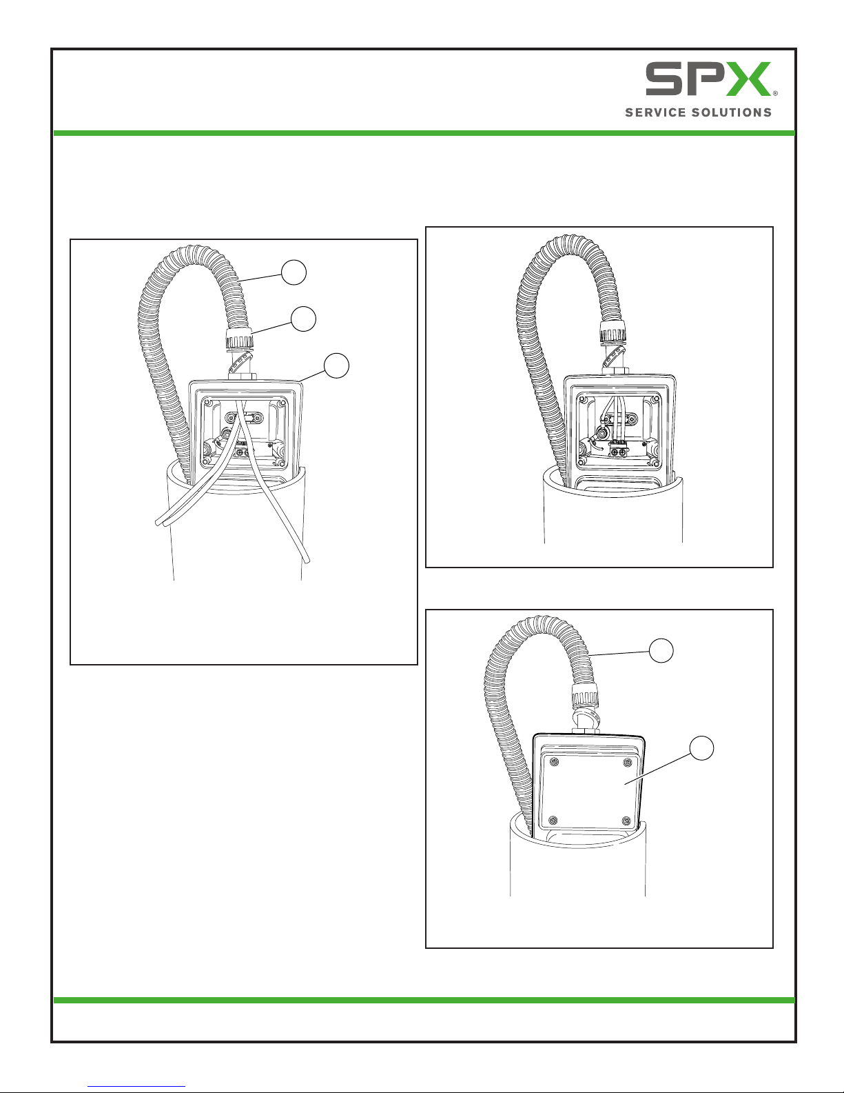
17. Feed wires into the hole in the top of the EVSE
and attach 1/2-in. liquid-tight exible conduit
with a liquid-tight tting.
A
B
C
A. 1/2-in. liquid-tight exible conduit
B. Liquid-tight tting
C. EVSE
Figure 21. Wires Inserted into EVSE and
Conduit Installed
18. Cut wires to length.
19. Strip wires and wire them into the EVSE. Refer
to label on inside of EVSE cover or details on
circuit board. Torque terminal screws to 10.62
± 1 in-lb (1.2 ± 0.12 Nm).
Figure 22. Wires Installed into EVSE
20. Install EVSE cover.
A
B
A. 1/2-in. liquid-tight exible conduit
B. EVSE cover
Figure 23. EVSE Cover Installed

18
Power Xpress™ Bollard Charge Station
Installation Guide
EL-50600-17 Rev. A
21. Apply decal to the front of the EVSE cover.
22. Continue lowering the EVSE until the front
edge of the EVSE bottom cover rests on the
ledge in the bollard front opening.
B
A
A. EVSE bottom cover
B. Ledge in bollard front opening
Figure 24. EVSE Lowered into Position
WARNING: The lower edge of the EVSE
bottom cover must rest on the ledge
of the bollard. Failure to position the
EVSE correctly in the opening will cause
damage to the EVSE when the locating
set screw is tightened.
WARNING: Never use any other size set
screw to secure the EVSE in place. If
the set screw is too long, it will prevent
installation of the upper cover.
23. Push any excess conduit down into the bollard.
A loop will extend above the bollard and t in
the top cover.
Figure 25. Excess Conduit Pushed into Bollard
24. Install the locating set screw to 50 ± 5 in-lb
(5.5 ± 0.55 Nm).
Figure 26. Tightening the Locating Set Screw
19
Power Xpress™ Bollard Charge Station
Installation Guide
EL-50600-17 Rev. A
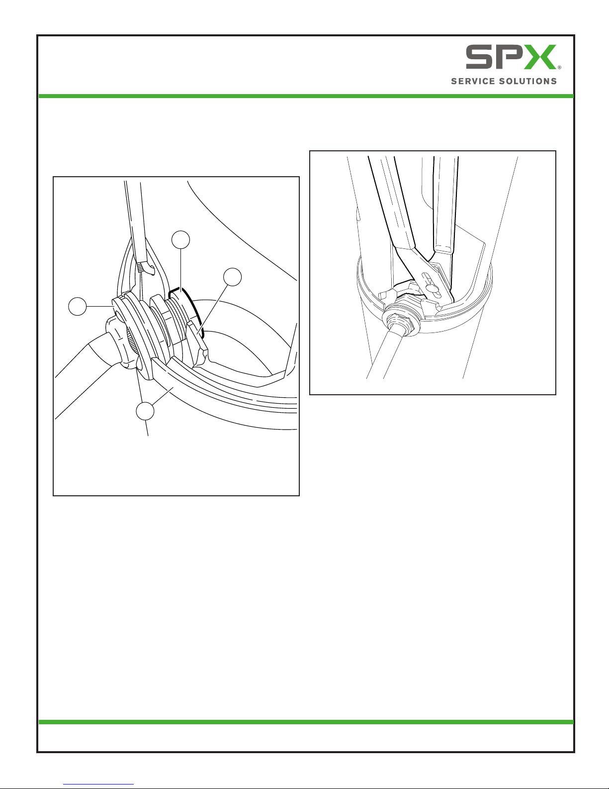
25. Position the strain relief at the bottom of the
side slot metal mounting bracket in the steel
bollard. Position such that the rubber grommet
(D) seats on the opening of the lower plastic
bollard cover.
D
C
A
B
A. Inner strain-relief nut
B. Metal mounting bracket
C. Seal
D. Rubber grommet
Figure 27. Strain Relief Placement
26. Tighten the inner strain-relief nut (A) inside the
bollard hand tight. Using expandable pliers,
tighten the nut an additional 1/4 turn.
Figure 28. Tightening the Strain-Relief Nut
NOTE: Do not overtighten the strain-relief nut. The
grommet may pull through.

20
Power Xpress™ Bollard Charge Station
Installation Guide
EL-50600-17 Rev. A
27. Carefully lower the upper plastic cover down
onto the bollard base.
A
B
A. Upper plastic cover
B. Metal bollard
Figure 29. Upper Bollard Lowered into Place
28. Use a small at-blade screwdriver or similar
tool to guide the upper plastic cover into the
seal.
WARNING:
WARNING:
RED STATUSLIGHT ILLUMINATED - SEE OPERATINGMANUAL FOR
FAULTINDICATION AND OPERATINGINSTRUCTIONS.
8.RETURN CABLE AND COUPLER BACKTO STOWABLEPOSITION AT EVSE.
NOTE: EVSEWILL RESUME CHARGING UPON RESTORATION OF INTERRUPTED GRID POWER.
7.UNPLUGVEHICLE COUPLER (CONNECTOR) FROM VEHICLE INLET (RECEPTACLE)- STATUS
INDICATOR CHANGES BACKTO AMBER ILLUMINATION STATE.
6.POST COMPLETION OF CHARG - STATUSLIGHT RETURNS TOSOLID GREEN ILLUMINATION
STATUS.
5.AFTER SAFETYTEST VERIFICATION - STATUSLIGHT BEGINS TO FLASH GREEN,INDICATING
VEHICLE IS CHARGING.
LA LUMIERE DE STATUTROUGE ECLAIREE - VOITLE MANUEL
OPERANT POUR L’INDICATIONDE FAUTEET LES
INSTRUCTIONS OPERANTES.
Sl appareil ne fonctionne pas selon les instructions
EMPLOI Ne pas utiliser ce peripherlque, contactez
TECHNICIEN QUALIFIEpour entretien ou reparation.
IFUNIT FAILSTO OPERATEPER THE OPERATINGINSTRUCTIONSDO NOTUSE
THISDEVICE, CONTACTQUALIFIEDTECHNICIANFOR SERVICEOR REPAIR.
AVERTISSEMENT:
AVERTISSEMENT:
FOR USE WITH ELECTRICVEHICLES ONLY
VENTILATION NOTREQUIRED
A
B
C
D
A. Upper plastic cover
B. Seal
C. Lower plastic cover
D. Small at-blade screwdriver
Figure 30. Seal Installation
29. While gently pressing down on the upper
plastic cover, carefully slide the screwdriver
around the bollard to extend the upper lip
of the seal over the upper plastic cover. The
upper cover may need to be tapped gently to
fully seat it in the seal.
CAUTION: Use care not to cut or damage the
seal during this procedure.
NOTE: When the upper plastic bollard cover is fully
seated, the rear cable-management holes
will be in line with the threaded holes in
the steel portion of the bollard base and the
rubber cable grommet will be centrally lo-
cated with respect to the rubber seal.
Verify the cable-management holes and the
rubber cable grommet are each properly
aligned.
30. Use a 5/16-in. hex-head wrench to install the
rear cable-management hook with the two
cable-management retaining screws. The
torque on the cable-management retaining
screws should be 60 ± 5 in-lb (6.8 ± 0.55 Nm).
Table of contents
Other SPX Batteries Charger manuals


