SPX Hankison GCU Series User manual

GCU Series
Refrigerated Type Compressed Air Dryers
Models: GCU-0.5, GCU-0.75, GCU-1.0, GCU-1.5, GCU-2.0, GCU-2.5, GCU-3.5
FORM NO.: 5003343 REVISION: 04/2015 READ AND UNDERSTAND THIS MANUAL PRIOR TO OPERATING OR SERVICING THIS PRODUCT.
INSTRUCTION MANUAL

CONTENTS
GENERAL SAFETY INFORMATION............................................................................. 1
RECEIVING, MOVING, AND UNPACKING ................................................................. 1
1.0 INSTALLATION
1.1 Location ................................................................................................................... 2
1.2 Mounting .................................................................................................................. 3
1.3 Piping Connections .................................................................................................. 3
1.4 Electrical Connections............................................................................................... 3
1.5 Moisture Separator .................................................................................................. 3
1.6 EDD Operation........................................................................................................... 3
2.0 OPERATION
2.1 Minimum/Maximum Operating Conditions ............................................................. 4
2.2 Start-up ..................................................................................................................... 4
2.3 Using the RS-485 Port Connector (J8) ..................................................................... 6
2.4 Using the USB Host Feature (J7)............................................................................... 7
2.5 Using the Ethernet Feature (J3) ............................................................................... 8
3.0 MAINTENANCE
3.1 Daily ........................................................................................................................... 14
3.2 Weekly ....................................................................................................................... 14
3.3 Monthly ..................................................................................................................... 14
3.4 Annually ..................................................................................................................... 14
4.0 TROUBLESHOOTING GUIDE
Models 0.5 & 0.75...................................................................................................... 15
Models 1.0 – 3.5 ........................................................................................................ 16
5.0 REFERENCE
Sizing ......................................................................................................................... 17
Engineering Data....................................................................................................... 18
Dryer Set Point Table................................................................................................. 19
Dryer Alarm Table ...................................................................................................... 20
Controller Screen Shots
Status Menu Screens............................................................................................. 21
Setup Menu Screens ............................................................................................. 22
Network Menu Screens......................................................................................... 23
6.0 WIRING DIAGRAMS
Model 0.5
:
120/230 VAC........................................................................................... 24
Model
0.75
: 120/230 VAC....................................................................................... 25
Models 1.0 – 2.5: 460 VAC........................................................................................ 26, 27
Model 3.5: 460 VAC .................................................................................................. 28, 29
Models 1.0 – 3.5: 575-460/3/60 Transformer Pack ................................................. 30
7.0 DIMENSIONS / WEIGHTS .................................................................................... 31
8.0 REPLACEMENT PARTS
Models 0.5 and 0.75 .................................................................................................. 32, 33
Models 1.0 through 3.5
Air-Cooled Units .................................................................................................... 34, 35
Water-Cooled Units ............................................................................................... 36, 37
Cabinet Panels (all models) ....................................................................................... 38
WARRANTY..................................................................................................................... 41

1
GENERAL SAFETY INFORMATION
1. PRESSURIZED DEVICES:
This equipment is a pressure containing
device.
• Donotexceedmaximumoperating
pressure as shown on equipment
serial number tag.
• Make sure equipment is depressurized before
working on or disassembling it for service.
2. ELECTRICAL:
This equipment requires electricity to
operate.
• Installequipmentincompliancewith
all applicable electrical codes.
• Standard equipment is supplied with electrical
enclosures not intended for installation in hazardous
environments.
• Disconnect power supply to equipment when
performing any electrical service work.
3. BREATHING AIR:
• Air treated by this equipment may
not be suitable for breathing without
further purification.
Refer to applicable standards and
specifications for the requirements
for breathing quality air.
RECEIVING, MOVING, AND UNPACKING
A. RECEIVING
This shipment has been thoroughly checked, packed and
inspectedbeforeleavingourplant.Itwasreceivedin
good condition by the carrier and was so acknowledged.
CheckforVisibleLossorDamage.Ifthisshipmentshows
evidence of loss or damage at time of delivery to you,
insist that a notation of this loss or damage be made on
the delivery receipt by the carrier’s agent.
B. UNPACKING
Check for Concealed Loss or Damage. When a shipment
has been delivered to you in apparent good order, but
concealed damage is found upon unpacking, notify the
carrier immediately and insist on his agent inspecting
the shipment. Concealed damage claims are not our
responsibility as our terms are F.O.B. point of shipment.
C. MOVING
Inmovingortransportingdryer,donottipdryeronto
its side.
D. STORAGE/SHUT DOWN
Dryer should not be stored outside (either
packed or unpacked) or exposed to the weather. Damage
to electrical and control components may result.
IMPORTANT: WATER-COOLED UNITS - If unit is shut down
below freezing temperatures, the water-cooled condenser
may freeze and cause permanent damage. Condenser must
be drained when the unit is shut down.
IMPORTANT: Do not store dryer in temperatures above
130°F (54.4°C).
2
IMPORTANT:READPRIORTOSTARTINGTHISEQUIPMENT
1.0 INSTALLATION
1.1 Location
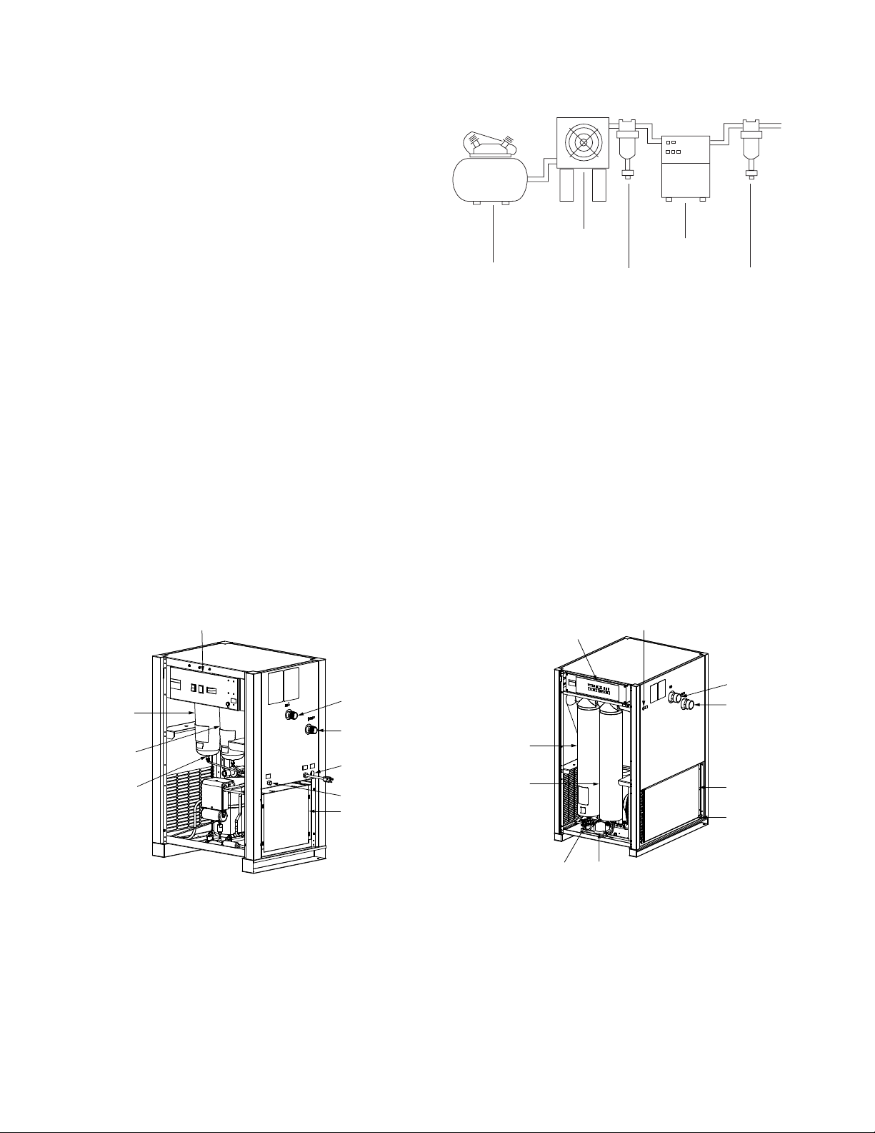
A. For typical placement in a compressed air system, see
drawing.
B. Air compressor intake – Locate air compressor so that
contaminants potentially harmful to the dryer (e.g.
ammonia) are not drawn into the air system.
C. Clearances Free air flow
Front 36 inches (914 mm)
Back 6 inches (152 mm)
Sides 36 inches (914 mm)
Service - To facilitate maintenance leave 36 inches
(914 mm) of clearance in front of dryer.
D. Standard units are designed to operate in ambients:
Air-cooled: 40 to 110°F (4.4 to 43°C).
Water-cooled: 40 to 130°F (4.4 to 54°C).
E. Installationsinaltitudesabove4500feet(1370meters)–
Dryer is adjusted to operate in altitudes up to 4500 feet
(1370meters).Ifdryerisinstalledinanaltitudeabove
this, and has not been preset at the factory for this
altitude, contact manufacturer’s Service Department.
F. The installation of a flexible connection prior to the
dryer is recommended to prevent possible damage from
vibration.
NOTE: Outdoor installation – Standard units are designed
for indoor installation. Contact manufacturer if installing
outdoors.
Aftercooler
Separator
Dryer
Oil Removal
Filter
Compressor
Electric Demand Drain (EDD)
3-Way Valve
Moisture Separator
Coalescing Filter
(Option)
Control Panel
Electrical Entry
Air Outlet
Air Inlet
Condenser
Drain Outlet
Models 1.0, 1.5, 2.0, 2.5, & 3.5Models 0.5 & 0.75
Moisture Separator
Coalescing Filter
(Option)
Float Drain
(Standard)
Condenser
Drain Outlet
Electrical Entry
(230 VAC)
Air Outlet
Air Inlet
Control Panel
3
1.2 Mounting
Mount the dryer on a level solid surface. Holes are provided
in the dryer base to permanently mount the dryer to the
floor.
1.3 Piping Connections
A. AirInlet-Connectcompressedairlinefromairsource
to air inlet. (Reference markings on dryer for air inlet/
outlet connection locations.)
Refer to Serial Number Tag for maximum
working pressure. Do not exceed dryer’s Maximum Working
Pressure.
NOTE:Installdryerinairsystemathighestpressurepossible
(e.g. before pressure reducing valves).
NOTE: Installdryeratcoolestcompressedairtemperature
possible. Maximum inlet compressed air temperature: 120°F
(49°C).Ifinletairexceedsthistemperature,precooltheair
with an aftercooler.
B. Air Outlet – Connect air outlet to downstream air lines.
C. Bypasspiping–Ifservicingthedryerwithoutinterrupting
the air supply is desired, piping should include inlet and
outlet valves and an air bypass valve.
D. Water cooled models – cooling water inlet and outlet
1. Connect cooling water supply to cooling water inlet.
2. Connect cooling water return line to cooling water
outlet connection.
NOTE: Strainer and water regulating valve are supplied on
water cooled models.
1.4 Electrical Connections
IMPORTANT:Usecoppersupplywiresonly.
A. Dryer is designed to operate on the
voltage, phase, and frequency listed on
the serial number tag.
B. Ifdryerissuppliedwithacordandplug,
install in a receptacle of proper voltage.
C. Electrical entry on larger dryers is through a hole in
thecabinet.Itislocatedontherightsidepanelwhen
facing the front of the unit. Connect power source to
terminal strip in electrical enclosure as shown on the
wiring diagram included with the dryer.
NOTE: Refrigeration condensing unit is designed to run
continuously and should NOT be wired to cycle on/off with
the air compressor.
1.5 Moisture Separator
A. Models 0.5 & 0.75:
Separator (and Oil Removal Filter where
applicable) has an internal drain which
automatically discharges condensate.
Models 1.0 - 3.5:
Separator (and Oil Removal Filter where applicable) has
an electronic demand drain (EDD) which automatically
discharges condensate.
NOTE:Itmaybedesirabletopipethecondensatefromthe
Automatic Drain outlet to a suitable drain.
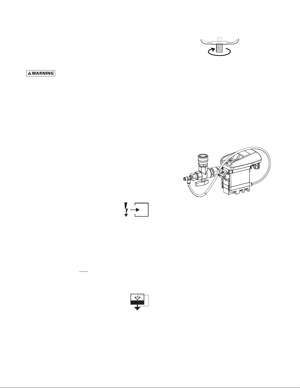
B. Models 0.5 & 0.75:
Separator has a knurled fitting with flexible drain tubing
attached. Be sure knurled fitting is tightened by turning
counter-clockwise before operating dryer.
TO CLOSE
TURN COUNTERCLOCKWISE
C. Models 1.0 - 3.5:
For manual draining, convenient dryer depressurization,
and EDD service, a three-way valve assembly has been
installed at the bottom of the moisture separator (and
cold coalescing filter where applicable). Review the
following for proper drain function:
• Automatic Draining - Valve handle should be
positioned parallel to the valve body (as shown),
with the arrow on the handle pointing toward the
EDD.Inthisposition,condensatewillowfromthe
bowl to the EDD.
• DrainIsolation(Shutdown) -Valvehandleshall be
turned perpendicular to the valve body (rotate 90°).
Inthisposition,condensateowisshutoff.
•
Manual Draining - Drain valve handle shall be rotated
slightly past the drain isolation position to allow
throttling through the valve for manual discharge
and depressurization.
• NOTE: The quick disconnect fitting allows removal
of the entire drain assembly. However, the unit
must be depressurized prior to disassembly or
serious injury may occur.
NOTE:Discharge is at system pressure. Drain line should be
anchored.
NOTE:Condensate may contain oil. Comply with applicable
laws concerning proper disposal.
1.6 EDD Operation
A. Verifythatisolationvalvesareopen.Ifthedrainfailsto
discharge after the valve is energized, the electronic
control circuit will repeatedly energize the valve in an
attempttoclearthedischargeport.If,after60seconds,
the drain still fails to discharge, the control circuit then
switchestothealarmmode.Inthismodethevalveis
de-energized and the red alarm light is activated on the
drain. The valve is then automatically energized every
80 seconds for 60 seconds. Check the drain operation.
Push drain (push-to-test) button on the drain or the
Electronic Controller (if equipped) to energize drain. A
flow of condensate and/or air should be present at the
drain outlet. The alarm mode automatically clears after
the drain returns to normal operation.
4
B. The condensate flows through the feed line (1) into
the condensate drain and accumulates in the housing
(2). A capacitive sensor (3) continuously registers the
liquid level. As soon as the container is filled, a fixed
waiting period begins during which more condensate
accumulates. After the waiting time has expired the
pilot valve (4) is then activated and the diaphragm
(5) opens the outlet line (6) for discharging the
condensate.
When the condensate drain has been emptied, the
outlet line is closed again quickly and tightly without
wasting compressed air.
NOTE: If there is no power to the control board for
a period of two weeks or more, it may return to the
default mode.
C. Program Monitor
Press and hold Program Mode button until Main Menu screen
appears. Use the Up and Down arrow buttons to scroll
through the list of submenu choices. Press Enter button
to view the submenu that is displayed. Press ESC to exit the
Main Menu and return to Display mode.
1. Language selection
a.
Use the ‘Up’ and ‘Down’ arrow buttons to scroll
through the list of languages (choice of 13 available:
English,Spanish,French,German,Portuguese,Italian,
Polish, Danish, Dutch, Norwegian, Finnish, Swedish
and Czech).
b. Press ‘Enter’ button to select the language that is
displayed.
c. Push ‘ESC’ at any time to return to the Main
Menu.
2. Setting Date & Time
a. Press ‘Enter’ to edit value.
b. Use the ‘Up’ and ‘Down’ arrow buttons to set year
(00 to 99 representing 2000 to 2099). Press ‘Enter’
to accept new value.
c. Use the ‘Up’ and ‘Down’ arrow buttons to set month
(1-12). Press ‘Enter’ to accept new value.
d. Use the ‘Up’ and ‘Down’ arrow buttons to set day
(01 to maximum for the month and year selected).
Press ‘Enter’ to accept new value.
e. Use the ‘Up’ and ‘Down’ arrow buttons to set hours
(00 to 23). Press ‘Enter’ to accept new value.
f. Use the ‘Up’ and ‘Down’ arrow buttons to set minutes
(00 to 59). Press ‘Enter’ to accept new value.
g. Press ‘Enter’ to accept new value. Push ‘ESC’ at any
time to return to the Main
Menu.
3. Setting Schedule
a.
Use the ‘Up’ and ‘Down’ arrow buttons to select
desired “Day of week + on/off”. Press ‘Enter’ to
adjust time.
b. Use the ‘Up’ and ‘Down’ arrow buttons to set hour
(00 to 23). Press ‘Enter’ to accept new value
NOTE:Ifthehoursettingis‘--:--’,Press‘Enter’again
to move the cursor under the “Day of week + on/
off”.
c. Use the Up and Down arrow buttons to set minutes
(00, 10, 20, 30, 40, 50; not shown if hour setting is
‘--:--’). Press ‘Enter’ to accept new value and return
to “Day of week + on/off”. Repeat steps a through
c as needed.
d. Push ‘ESC’ at any time to return to the Main
Menu.
4. Hours To Service
a. Use the ‘Up’ and ‘Down’ arrow buttons to scroll
through the range of permissible values (0 to 9999)
before service reminder is initiated. Press ‘Enter’
to move to next field. (Only hours that refrigeration
compressor is operating are counted).
2.0 OPERATION
2.1 Minimum/Maximum Operating Conditions
A. Maximum inlet air pressure: refer to dryer serial number
tag
B. Minimum inlet air pressure: 30 psig (2.1 kgf/cm
2
)
C. Maximum inlet air temperature: 120°F (49°C)
D. Maximum ambient temperature:
Air-cooled models: 110°F (43°C)
Water-cooled models: 130°F (54°C)
E. Minimum ambient temperature: 40°F (4.4°C)
2.2 Start-up
A. Models 0.5 & 0.75:
Energize compressor by positioning the on/off switch in
theon(I)position.Compressoronlightwillilluminate.
On/Off Power-On Dewpoint Indicator
Switch Light (Green)
B. Models 1.0 - 3.5:
Energizedryer.Greenpoweronlightwillilluminate.
IMPORTANT:Energizedryerdisconnectswitch(provided
by others, see NEC) 24 hours before refrigeration
compressor is started! Never use the disconnect switch
to shutdown the dryer for a extended period of time
(except for repair). Failure to follow these instructions
may result in a non-warrantable compressor failure.

5
b. Press ‘ESC’ at any time to return to the Main Menu.
NOTE: On dryers with air-cooled condensers, regular
condenser cleaning is recommended. Dirtiness
of ambient air at installation site will determine
frequency of service. Typically once a month is
recommended. Dryers contain an integral 3 micron
filter. As the filter element accumulates solid
contaminants, differential pressure increases. Solid
particulate load in the compressed air supply will
determine frequency of service. Typically element
changeout is recommended at least
annually.
5. Push ESC button to exit program mode.
6. Manual Operation
a. To manually turn the refrigeration system on or off
use ‘On/Off’ button; Push ‘Schedule On/Off and
Enter’ button to return to schedule.
NOTE: After power interruption dryer will reenergize
in Manual override, refrigeration system off. To
restart Schedule: Push ‘Schedule On/Off and Enter’
button.
D. Starting dryer
IMPORTANT: Dryer must be energized 24 hours before
starting refrigeration compressor.
NOTE:Itisrecommendedthatdryerbestarted15minutes
before compressed air flow begins.
1. On water-cooled models: after 24 hours, begin cooling
water flow.
2. Check for proper electrical voltage.
3. Slowly pressurize unit air side by opening inlet isolation
valve. Check for leaks.
4. After 15 minutes, open outlet isolation valve slowly.
5. Close air bypass valve.
6. Dryer may be operated in Manual or scheduled modes.
NOTE: Check for correct phasing of unit. On air-cooled
models: check fan rotation (air must be pulled through the
condenser). Fans may not start immediately or may cycle
onandoff.Ifrotationisinthewrongdirectionfollowthe
procedure below. On water-cooled models: After starting
dryer if an unusual noise is heard and the discharge line
does not get hot, stop the dryer, reverse two power leads,
restart, and verify discharge line gets hot.
Manual Mode - push On/Off button - refrigeration
compressor will start and run, green Compressor-on
lightwillilluminate.Inthismodecompressorwillrun
continuously and will not be turned on and off by the
monitor. MANUAL MODE will appear on interface panel.
Schedule Mode - push Schedule On/Off and Enter
button. SCHEDULED MODE will appear on the interface
panel. The compressor will then turn on or off as
programmed.
NOTE: Dryer may be returned to the Manual Mode at
any time using the ‘Schedule On/Off and Enter’ button
or by pressing On/Off button. MANUAL MODE will appear
on interface panel. To reinstitute Schedule, push the
‘Schedule On/Off and Enter’ button again.
NOTE: Restart after the power interruption. Unit will be in
MANUAL MODE mode, refrigeration compressor, off when
power is restored after power interruption.
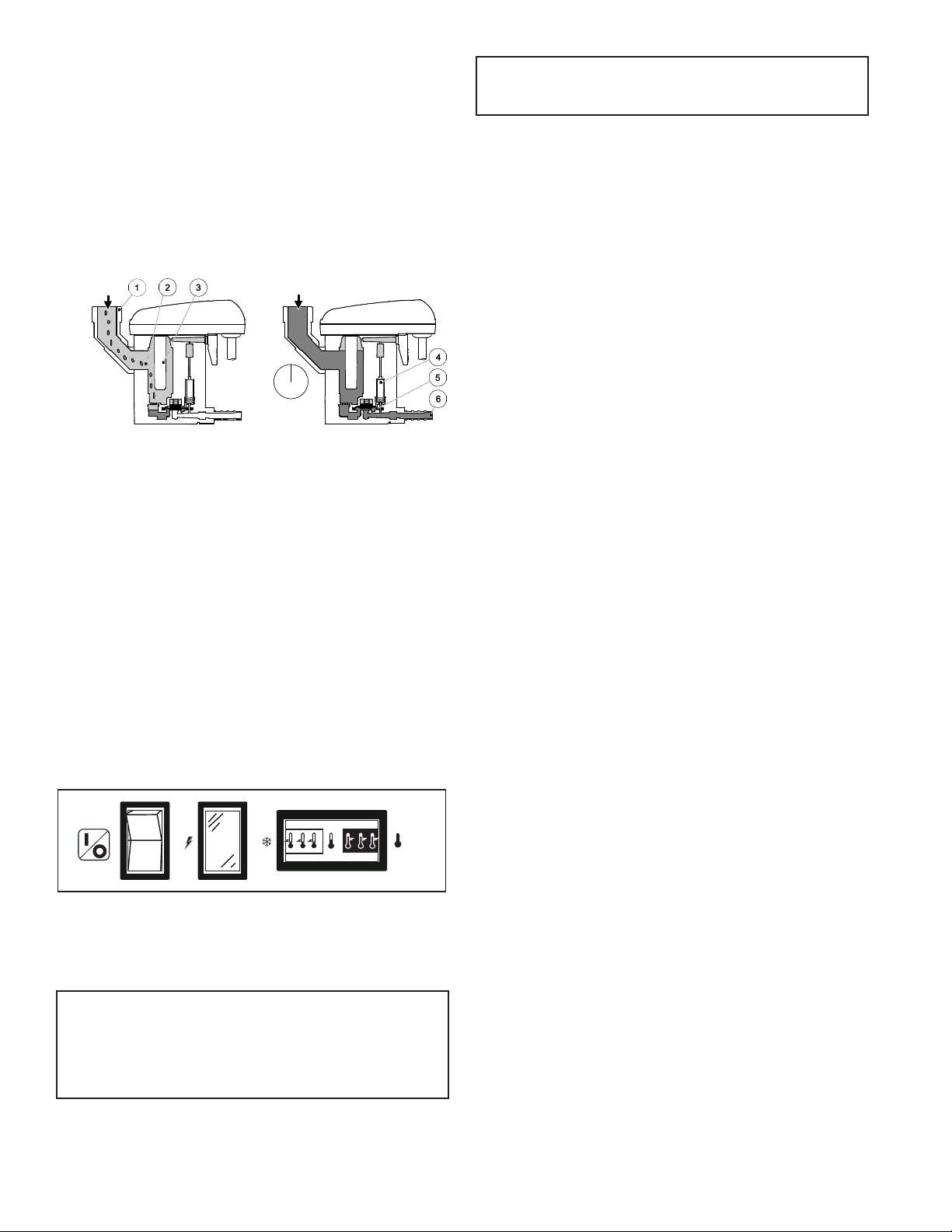
1. TemperatureIndicator
2. OperatorInterfaceDisplay
3. Power-on Light
4. Compressor-on Light
5. Alarm / Service Light
6. Schedule On/Off and Enter Button
a. InDisplay Mode: Press to toggle between
SCHEDULED MODE and MANUAL MODE.
b. InProgram Mode:
i. Press to move to a lower level menu.
ii. Press to accept a value that has been edited.
7. Program Mode (i) and Esc
a. InDisplay Mode: Press and hold to enter Pro-
gram Mode.
b. InProgram Mode: Press to move to a higher
level menu.
8. Up Arrow
a. InDisplay Mode: Press to cycle to next Display
screen
b. InProgram Mode:
i. Press to view the next item in a list or to
increment a variable to a higher value.
ii. When the top of the list (or highest value) is
displayed, pressing the up button will cause
the display to wrap to the bottom of the list
(or lowest value).
9. Down Arrow
a. InDisplay Mode: Press to cycle to previous Dis-
play screen
b. InProgram Mode:
i. Press to view the previous item in a list or to
decrement a variable to a lower value.
ii. When the bottom of the list (or lowest value)
is displayed, pressing the down button will
cause the display to wrap to the top of the
list (or highest value).
10. 1/0: Press at any time to turn the dryer on/off.
11. Drain test: Press at any time to momentarily open
the drains.
12. Reset: Press at any time to clear the alarm/service
message (if shown) and the alarm LED.
CONTROL PANEL
1 2 3 4 5
67 8 9 10 11 12
6
7. To reinstitute SCHEDULED MODE, push ‘Schedule On/Off
and Enter’ button.
IMPORTANT: Dryer must be energized 24 hours before
refrigeration compressor is started
E. Operating check points
1. Check that green Power-on light is illuminated
2. Check that green Compressor-on light is illuminated if
dryer is on in the manual mode or it is a scheduled on
time
IMPORTANT: Refrigeration compressor must be restarted
after power interruption.
3. Check interface panel
NOTE: Interface panel will scroll through three screens
(Current Time/Operating Status, Hours to Service and Total
Operating Hours).
a. Verify that current time is correct
b. CheckHRSTOSERVICE:thisindicatestimeremaining
until service is required; allow time for required
maintenance items to be ordered
c. Check operating status:
MANUAL MODE - Dryer is either running continuously
(not being controlled by the scheduled on/off times)
or the refrigeration compressor has been shut off
using the ‘On/Off’ button.
SCHEDULE MODE - Refrigeration compressor
is being turned on and off by the monitor per-
programmed schedule (see B.3. to set schedule).
d. Check Temperature indicator - indicator should read
in the green area.
e. Check Alarm/Service light If illuminated, check
Interfacepanel.
1) IfSERVICEDRYERappears,scheduledmaintenance
timehaselapsed(HRSTOSERVICEis0).Perform
needed service and reset service interval (see B.3.).
2)IfALARMappears,adryerfaultisindicated;see
Troubleshooting Guide for possible remedies.
After fault correction push Reset button to turn
Fault alarm off.
Type of FAULTS:
LOW PRESSURE - the refrigeration compressor
control circuit has opened because of low suction
pressure.
HIGH PRESSURE - the refrigeration compressor
control circuit has opened because of high head
pressure. The high pressure switch must be reset
manually once the fault is corrected. Red reset
button is located on pressure switch inside unit.
HIGHTEMPERATURE-compressedairtemperature
is above the set point.
COMPRESSOR - Normally open (NO) auxiliary
contact on the compressor contactor is open
when the dryer is on.
HEATER - Normally closed (NC) auxiliary contact
on the compressor contactor is open when the
dryer is off.
TEMP SENSOR - Occurs if the temperature
sensorcircuitisopenorshorted.Ifopen,none
of the LED’s in the temperature display will
be illuminated. If shorted, all the LEDs in the
temperature display will be illuminated.
DRAIN-electricdraincontainsahighwaterlevel
alarm that activates if drain fails to discharge.
f. Check drain operation - push Drain (push-to-
test) button to energize electric drain. A flow of
condensate and/or air should be present at the drain
outlet.
2.3 Using the RS-485 Port Connector (J8)
This connector provides RS-485 compatible signals from
the internal master microprocessor. Using jumpers on
the headers supplied near the connector (J12), 120 ohm
termination resistors can be connected and the system can
be connected for either two-wire or four-wire operation
(half or full duplex). To connect the termination resistors,
install jumpers on J12 in the direction shown by the white
bars printed above the connector.
IfthejumpersareremovednoterminationoftheRS-485
bus is in effect. Usually, these jumpers must be in position
for proper operation of the bus.
J10containsthetwo-wire/four-wirejumper.Ifthejumperis
setinW2place,thecircuitissetupfortwo-wireoperation.If
the jumper is set in W4 place, the circuit is set up for four-wire
operation. Selection of jumper settings must be determined
by the customer’s system. The jumpers are supplied as
standard and are installed as shown at the factory. Be sure
to set the jumpers properly for your system.
RS-485 Pinout
Following is the pinout for J8, the RS-485 communications
connector.
1 A
2 B
3 Z
4 Y
When connected in two-wire mode, the bus wires may be
connected to pins 1 & 2. Also note that when in two-wire mode,
one termination resistor jumper should be removed to prevent
theterminationfrombeingtoolowinvalue.Itmaybestored
on the top set of pins on J12. Those pins are not connected.
Please make sure that your connections are properly made. This
connector is a 4-pin terminal block. Mating connectors are not
supplied. The electrical signals supplied by this connector are
TIA/EIA-485Acompliant.Agoodcableshouldbeusedtotransmit
signals such as Belden 3109A or equivalent.
Communication Parameters:
RS-485 Parameters
Baud Rate 19200
Data Bits 8
Parity None
Stop Bits 1
Flow Control None
ModbusDropI/O Factory Default = 1
(user adjustable 1 - 247 )

7
2.4 Using the USB Host Feature (J7)
The EMM connect is equipped with a USB Host port located
at J7 on the control board which allows for the connection
of a USB flash drive. The USB flash drive can be used for
data logging, event history, and installing software updates.
1. USB Data Logging
When a USB flash drive is installed in the controller it will begin
to automatically record key dryer operating parameters:
timestamp, dryer status, service timer, total compressor run
timer, discharge temperature, evaporator inlet temperature,
evaporator outlet temperature, and dryer % load.
These values will be written every 10 seconds to a comma
separated value file stored in the root folder of the USB
flash drive. Each day a new comma separated value file will
be created for storing the samples for that day. Comma
separated value files older than 60 days will be automatically
deleted.
2. USB Event History
When a USB flash drive is installed in the controller it will
begin to automatically log all dryer events: power loss,
power recovery, alarms, state (standby/running), and mode
(manual/scheduled/remote).
Events are timestamped and recorded in the EVENT.TXT file
stored in the root folder of the USB flash drive.
8
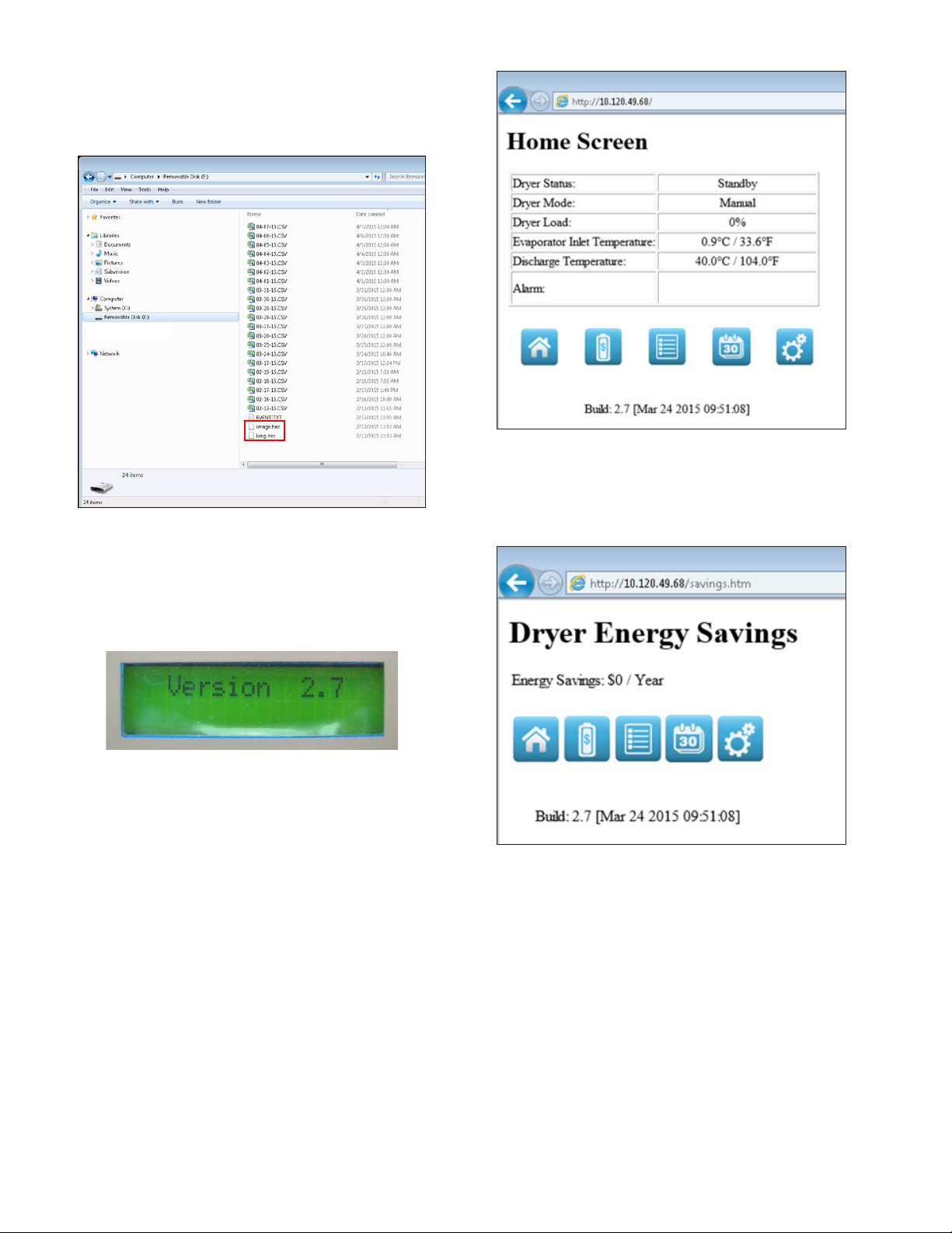
3. USB Bootloader
Firmware updates for the EMM connect can be performed via
theUSBashdrive.Inordertoperformarmwareupdate;
place the image.hex and lang.hex files provided by SPX in
the root folder of a USB thumb drive.
With the dryer controller powered off install the USB flash
drive in the USB host port on the EMM connect. Then while
holding the enter button on the front panel apply power to
the controller. Once the power LED begins blinking rapidly
you can release the enter button. The controller will reboot
when the update is complete. On startup the current
firmware version will be shown on the text display.
2.5 Using the Ethernet Feature (J3)
The EMM connect is equipped with an Ethernet port located
at J3 on the control board which allows the customer to
connect the dryer to a local area network. The customer
can then monitor the dryer status and performance via Web
InterfaceorModbusTCP.
1. WebInterface
After assigning an IP address to the dryer the IP address
can be entered into the address bar of any web browser to
connect to the web interface.
The first page displayed is the home screen. Displayed on
this page are the dryers operating status, operating mode,
current dryer load, evaporator inlet temperature, discharge
temperature, and any active alarms. The navigation bar at
the bottom of this page can be used to view energy savings,
event history, scheduler, and settings.
Figure 1: Home Screen
The energy savings page shows the estimated annual energy
savings based on your actual energy cost (entered on the
settings page) and the average dryer load over the last 30
days.
Figure 2: Energy Savings
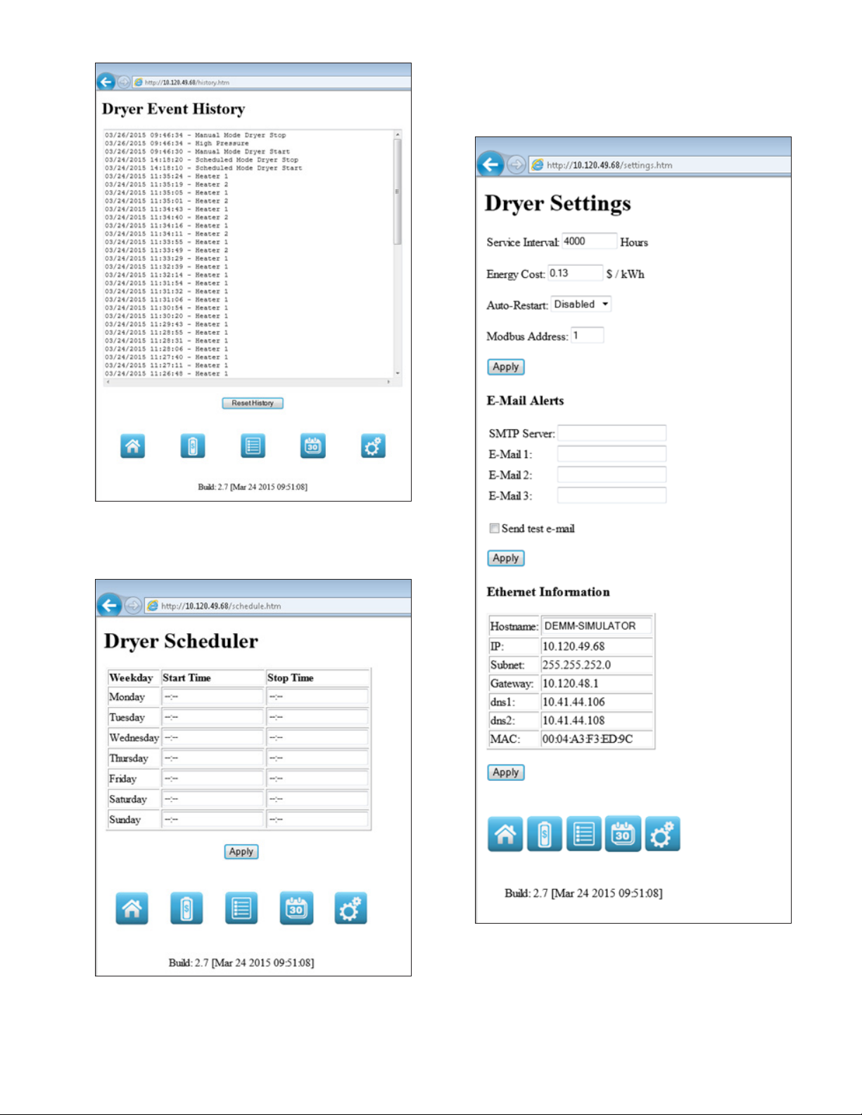
The event history page shows the last 64 timestamped
events that have occurred on the dryer. These events include
power failure/recovery, dryer mode changes, dryer status
changes, and alarms.
9
Figure 3: Event History
The dryer scheduler page allows the customer to view/edit
the daily start/stop times that will be used when operating
the dryer in scheduled mode.
Figure 4: Schedule
The dryer settings screen allows the customer to view/edit
various dryer set points and setup E-mail alerts that will send
an e-mail to up to 3 different e-mail addresses whenever an
alarm or warning occurs on the dryer.
Figure 5: Settings
2. Modbus TCP
The Modbus TCP connection allows you to continuously
monitor the dryer from a DCS system which implements
a Modbus TCP master. The dryer controller implements
a ModbusTCP server on port 502. The following Modbus
register table provides a list of data that is available.

10
Modbus Registers
Holding Register
Reference Address Name Units Description
40001 0x0000 DRYER_STATUS StatusID StatusIDforthedryer
40002 0x0001 ALARM_STATUS Flag Bits Alarm flag bits
40003 0x0002 WARNING_STATUS Flag Bits Warning flag bits
40004 0x0003 RESERVED N/A Reserved
40005 0x0004 SERVICE_TIMER Hours Timer to service
40006 0x0005 TOTAL_TIMER Hours Total operating hours
40007 0x0006 EVAPORATOR_INLET_TEMP 1/10th Degree Celsius Evaporator inlet temperature
40008 0x0007 DISCHARGE_TEMP 1/10th Degree Celsius Discharge temperature
40009 0x0008 DRYER_LOAD % Dryer load
40010 0x0009 SAVINGS Dollars / Euros Energy savings
40011 0x000A EVAPORATOR_OUTLET_TEMP 1/10th Degree Celsius Evaporator outlet temperature
40012 0x000B
40013 0x000C
40014 0x000D
40015 0x000E
40016 0x000F
40017 0x0010 DRYER_MODEL Model_ID Dryer model
40018 0x0011 DRYER_MODE Mode_ID Dryer mode
40019 0x0012 SERVICE_INTERVAL Hours Service interval
40020 0x0013 AUTO_RESTART Boolean Auto-restart (0=Disabled, 1=Enabled)
40021 0x0014 UI_LANGUAGE Language_ID User interface language
40022 0x0015 RESERVED N/A Reserved
40023 0x0016 RESERVED N/A Reserved
40024 0x0017 ENERGY_COST Integer Energy cost (Cost / kWh)
40025 0x0018 AUDIBLE_ALARM Boolean Audible Alarm (0=Disabled, 1=Enabled)
40026 0x0019 MODBUS_ADDRESS Integer Modbus Address
40027 0x001A FULL_POWER Watts Full load power
40028 0x001B
40029 0x001C
40030 0x001D
40031 0x001E
40032 0x001F
40033 0x0020 ALARM_MSG_1 Integer Alarm message #1 phrase id
40034 0x0021 ALARM_MSG_2 Integer Alarm message #2 phrase id
40035 0x0022
40036 0x0023
40037 0x0024
40038 0x0025
40039 0x0026
40040 0x0027
40041 0x0028 INPUT_STATUS Flag Bits DigitalInputStatus
40042 0x0029 OUTPUT_STATUS Flag Bits Digital Output Status
40043 0x002A ANALOG[0] 1/10th Degree Celsius AnalogInput[0]
40044 0x002B ANALOG[1] 1/10th Degree Celsius AnalogInput[1]
40045 0x002C ANALOG[2] 1/10th Degree Celsius AnalogInput[2]
40046 0x002D PV 1/10th Degree Celsius Process value
40047 0x002E P Integer P Term
40048 0x002F I Integer ITerm
40049 0x0030 D Integer D Term
40050 0x0031 FIXED_LOAD Seconds Fixed cycle load period
40051 0x0032 FIXED_UNLOAD Seconds Fixed cycle unload period
40052 0x0033 FIXED_TIME Seconds Fixed mode timeout period
40053 0x0034 DELTA_PID_CALC 1/10th Degree Celsius PIDcalculationsetpoint
40054 0x0035 DELTA_PID_CTRL 1/10th Degree Celsius PIDcontrolsetpoint

11
Modbus Register Details
Page 1 of 3
Dryer Status
Register 40001
Decimal Hex Description
0 0x0000 Standby
1 0x0001 Fixed
2 0x0002 PID
3 0x0003 Reserved
4 0x0004 Reserved
5 0x0005 Reserved
6 0x0006 Reserved
7 0x0007 Reserved
Dryer Alarm Flags
Register 40002
Bit Mask Description
0 0x0001
High Discharge Temperature
1 0x0002 High Refrigerant Pressure
2 0x0004 Low Refrigerant Pressure
3 0x0008 Compressor #1
4 0x0010 Compressor #2
5 0x0020 Oil Protection #1
6 0x0040
Oil Protection #2
7
0x0080
Phase Reversal
8
0x0100
Phase Loss
9
0x0200
Evaporator Temperature Sensor Failure
10
0x0400
GlycolTemperatureSensorFailure
11
0x0800
Evaporator Outlet Temperature Sensor Failure
12
0x1000
Discharge Temperature Sensor failure
13
0x2000
High Super Heat
14
0x4000
Reserved
15
0x8000 Reserved
Dryer Warning Flags
Register 40003
Bit Mask Description
0 0x0001 High Evaporator Temperature
1 0x0002 HighGlycolTemperature
2 0x0004 Heater #1
3 0x0008 Heater #2
4 0x0010 Drain #1
5 0x0020
Drain #2
6 0x0040
Filter #1
7 0x0080
Filter #2
8 0x0100 Reserved
9 0x0200 Reserved
10 0x0400 Reserved
11 0x0800 Reserved
12 0x1000 Reserved
13 0x2000 Reserved
14 0x4000 Reserved
15 0x8000 Reserved

12
Modbus Register Details
Page 2 of 3
Dryer
Model
Register 40017
Decimal Hex Description
0 0x0000
Non-Cycling MRD
1 0x0001 Non-Cycling LRD
2 0x0002 ES-MRD 90
3
0x0003 ES-MRD
120
4
0x0004 ES-MRD 140
5
0x0005 ES-MRD
190
6
0x0006 ES-MRD
245
7
0x0007 ES-MRD
280
8
0x0008 ES-MRD
360
9
0x0009 ES-MRD
450
10
0x000A ES-MRD
540
11
0x000B ES-MRD
675
12
0x000C
DEMM 800
13
0x000D
DEMM 1000
14
0x000E
DEMM 1250
15
0x000F
DEMM 1500
16
0x0010
DEMM 1750
17
0x0011
DEMM 2000
18
0x0012
DEMM 2500
19
0x0013
DEMM 3000
20
0x0014
Reserved
21
0x0015
Reserved
22
0x0016
Reserved
23
0x0017
Reserved
24
0x0018
Reserved
25
0x0019
Reserved
26
0x001A
Reserved
27
0x001B
Reserved
28
0x001C
Reserved
29
0x001D
Reserved
30
0x001E
Reserved
31
0x001F
Reserved
Dryer Mode
Register(s) 40018
Decimal Hex Description
0 0x0000
Manual Mode
1 0x0001 Scheduled Mode
2 0x0002 Remote Mode
3 0x0003 Reserved
4 0x0004 Reserved
5 0x0005 Reserved
6 0x0006 Reserved
7
0x0007 Reserved

13
Modbus Register Details
Page 3 of 3
UILanguage
Register(s) 40021
Decimal Mask Description
0 0x0000
English
1 0x0001 Spanish
2 0x0002 French
3 0x0003 German
4 0x0004 Portuguese
5 0x0005 Italian
6 0x0006 Polish
7 0x0007 Danish
8 0x0008 Dutch
9 0x0009 Norwegian
10 0x000A Finnish
11 0x000B Swedish
12 0x000C Czech
13 0x000D Reserved
14 0x000E Reserved
15 0x000F Reserved
14
3.0 MAINTENANCE
3.1 Daily
A. Check separator to make sure the automatic drain is
discharging.
3.2 Weekly
A. Blow down the separator weekly by pushing the test
button on the control panel.
3.3 Monthly
A. Clean off the accumulated dust and dirt on the
condenser coil monthly.
3.4 Annually
A. Replace the filter element in the moisture separator
annually. Also replace the cold coalescing filter
element annually where applicable.
B. Replace the drain service unit annually.
C. Maintenance kits are available to facilitate annual
maintenance.
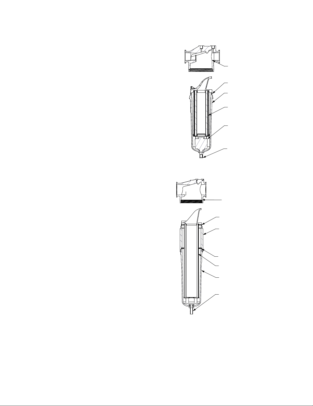
Models 0.5 & 0.75
Head
Bowl O-Ring
Bowl
Element
Float Drain
Drain Line
Connection
Models 1.0 – 3.5
Head
Extrusion O-Ring
(*Models 600-750 Only)
Extrusion
(*Models 600-750 Only)
Element
Bowl O-Ring
Bowl
Drain Connection

15
SYMPTOM POSSIBLE CAUSE(S) CORRECTIVE ACTION
A) Water downstream of dryer 1. Residual free moisture remaining in
downstream pipelines
2. Air bypass system is open
3. InletandOutletconnectionsarereversed
4. Air lines downstream of dryer are exposed
to temperatures below the dew point.
5. Excessive free moisture (bulk liquid) at
dryer inlet.
6. Condensate not being drained
Drain mechanism is clogged or
inoperative.
7. Drain line is restricted or frozen.
8. Electric drains-timer not set to allow for
sufficient condensate removal.
9. Dryer overloaded resulting in elevated
dew point.
10. Refrigeration system not functioning
Blow out system with dry air
Check valve positions
Check for correct connection
Insulateorheattraceairlinesexposedtolow
ambients or dry air to lower dew point
Installseparatoraheadofdryer
Replace drain mechanism if inoperative.
Open drain line.
Electric drains-reset time so that all liquid is
discharged
Check inlet air temperature and pressure,
flow rate (compressor capacity) and ambient
air or water temperature.
See D below
B) High pressure drop across dryer 1. Excessive air flow
2. Freezing of moisture in evaporator
because of refrigeration system fault
3. Separator filter element clogged
Check flow rate
See D below
Replace filter element
C) Dew point indicator in red area 1. Dryer overloaded resulting in high air
outlet temperature
2. Refrigeration system not functioning
properly resulting in high air outlet
temperature
See A 7
See D below
D) Refrigeration system not
functioning properly
1. Power on light off
2. Refrigeration compressor cycles
on and off
a. Power failure
b. Line disconnect switch open
c. Blown fuses, open breaker
d. Faulty wiring, loose terminals
a. High or low ambient conditions
b. Air-cooled - Dirty, clogged condenser fins,
obstructed flow across condenser, faulty
fan motor or fan control switch.
Check for power to unit
Close disconnect switch
Check for continuity
Have electrician check electrical connections.
Check min./max. temperature ranges
Clean condenser and check for free air
flow, if problem persists contact qualified
refrigeration repairman or manufacturer’s
service department.
4.0 TROUBLESHOOTING GUIDE: MODELS 0.5 & 0.75

16
TROUBLESHOOTING GUIDE: MODELS 1.0 – 3.5
SYMPTOM POSSIBLE CAUSE(S) CORRECTIVE ACTION
A) Water downstream of dryer 1. Residual free moisture remaining in
downstream pipelines
2. Air bypass system is open
3. InletandOutletconnectionsarereversed
4. Air lines downstream of dryer are exposed
to temperatures below the dew point.
5. Excessive free moisture (bulk liquid) at
dryer inlet.
6. Condensate not being drained
7. Dryer overloaded resulting in elevated
dew point.
8. Refrigeration system not functioning
1. Blow out system with dry air
2. Check valve positions
3. Check for correct connection
4. Insulateorheattraceairlinesexposedto
low ambients or dry air to lower dew point
5. Installseparatoraheadofdryer
6. See C below
7. See C below
8. See C below
B) High pressure drop across dryer 1. Excessive air flow
2. Freezing of moisture in evaporator
because of refrigeration system fault
3. Filter loaded with solid particulates
1. Check flow rate
2. See C below
3. Replace filter element
C) Checkpoint faults
1. Power on light off
2. Compressor on light off
3. Alarm/Service alert light on
-check Display for active
conditions
SERVICEDRYER
LOW PRESSURE
HIGHPRESSURE
NOTE:Ifhighrefrigerantpressure
occurs, switch must be manually
reset
HIGHTEMPERATURE
(also observed as high reading on
temperature indicator)
DRAIN
COMPRESSOR
HEATER
TEMP SENSOR
a. Power failure; open circuit
a. Compressor commanded off by manual
switch or programmed schedule
b. Open circuit
c. Control circuit open on high or low
pressure cutout
a. Service interval specified has elapsed
a. Hot gas bypass valve requires adjustment
b. Low on refrigerant
a. Lack of condenser cooling
Air-cooled - Ambient temperature too
high, clogged condenser fins, obstructed
flow across condenser, faulty fan motor or
fan control switch.
Water-cooled - Cooling temperature too
high, flow too low, clogged strainer, faulty
water regulating valve
a. Dryer overloaded
b. Refrigeration system off or not cooling
sufficiently
a. Drain line restricted or frozen
b. Drain mechanism faulty
a. Faulty compressor contactor.
b. Faulty N.O. auxiliary contact on
compressor contactor.
a. Faulty compressor contactor.
b. Faulty N.C. auxiliary contact on
compressor contactor.
a. Temperature sensor or wiring to sensor is
open (none of LED’s in the temperature
display will be illuminated).
b. Temperature sensor or wiring to sensor is
shorted (all of the LEDs in the temperature
display will be illuminated).
a. Check for power to dryer
a. Check current command status
b. Check power to compressor
c. Check display for fault
a. Perform scheduled service
a. Contact qualified technician or
manufacturer’s service department
Check air temperature 6” in front of
condenser; Clean condenser and check
for free air flow; Check fan and switch
operation
Check cooling medium temperature and
flow, clean strainer, check valve operation
a. Check compressed air flow, temperature,
and pressure
b. Check power to unit, power to
compressor, Low or High pressure faults
Have qualified technician evaluate system
a. Open drain line
b. Turn 3-way valve to horizontal position
and open petcock for manual draining.
Rebuild drain mechanism.
a. Check wiring and operation of contactor.
b. Check wiring and operation of auxiliary
contact.
a. Check wiring and operation of contactor.
b. Check wiring and operation of auxiliary
contact.
a. Replace sensor or repair wiring.
b. Replace sensor or repair wiring.
NOTE: After fault correction, press reset button to clear display

17
5.0 REFERENCE
SIZING
Determining dryer capacity at actual operating conditions
To determine the maximum inlet flow capacity of a dryer
at various operating conditions, multiply the rated capacity
from Table 1 by the multipliers shown in Table 2.
Example: How many scfm can an air-cooled model 1.5 handle
when compressed air to be dried is at 200 psig and 100°F;
ambient air temperature is 80°F?
Answer: 160 x 1.22 x 1.12 = 218 scfm.
TABLE 1
Rated capacity (scfm) and pressure drop @ 100 psig inlet
pressure, 100°F inlet temperature, and 100°F ambient
temperature
MODEL 0.5 0.75 1.0 1.5
Rated capacity
of air-cooled
models (scfm)
60 Hz
50 Hz
50
42
70
58
100
83
160
133
MODEL 2.0 2.5 3.5
Rated capacity
of air-cooled
models (scfm)
60 Hz
50 Hz
200
167
240
200
330
275
TABLE 2
Air capacity correction factors (Multipliers)
INLETCOMPRESSEDAIRCONDITIONS
INLET
PRESSURES
INLETTEMPERATURES
80°F 90°F 100°F 110°F 120°F
psig kgf/cm227°C 32°C 38°C 43°C 49°C
50
80
100
125
150
175
200
3.5
5.6
7.0
8.8
10.5
12.3
14.0
1.35
1.50
1.55
1.63
1.70
1.75
1.80
1.05
1.17
1.23
1.31
1.37
1.42
1.47
0.84
0.95
1.00
1.07
1.13
1.18
1.22
0.69
0.79
0.82
0.91
0.95
0.99
1.03
0.56
0.66
0.70
0.74
0.80
0.84
0.89
COOLINGMEDIUM*
AMBIENT
TEMPERATURE
MULTIPLIER
°F °C
80
90
100
110
27
32
38
43
1.12
1.06
1.00
0.94
*Air-cooled models; water-cooled models use 1.15 multiplier if cooling
water is below 35°C, 95°F.

18
ENGINEERING DATA
Models 0.5 0.75 1.0 1.5 2.0 2.5 3.5
Air System Data
Maximum / Minimum Inlet Air Pressure (compressed air at inlet to dryer) 232 psig (16 barg) / 30 psig (2 barg)
Maximum / Minimum Inlet Air Temperature (compressed air at inlet to dryer) 120°F (49°C) / 40°F (4.4°C)
Maximum / Minimum Ambient Temperature 110°F (43°C) / 40°F (4.4°C) Air-Cooled: 110°F (43°C) / 40°F (4.4°C) / Water-Cooled: 130°F (54°C) / 40°F (4.4°C)
Outlet Air Temperature (nominal at rated conditions) 40°F (4.4°C)
Refrigeration System Data
Refrigeration Capacity @ 35°F Evaporator & 100°F Ambient (BTU/hr) 60 Hz 4510 7130 8900 15200 19200 22000 30500
50 Hz 4600 7200 7420 12700 16000 18300 25400
Refrigerant Type R-134A
Refrigerant Charge See Data Tag on Dryer
Suction Pressure Setting - Hot Gas Bypass Valve (psig) 30.5 psig (2.1 barg)
Compressor Control Ranges (out-in) High N/A 281 - 190 psig (19.4 - 13.1 barg)
Low N/A 22 - 34 psig (1.5 - 2.3 barg)
Air-Cooled Condensers
Air Flow Across Condenser (cfm) (air-cooled models) 60 Hz 300 450 710 1070 2470 1680 2170
50 Hz 250 370 590 890 2060 1400 1810
Condenser Fan Switch Setting (in-out) Fan 1 110 - 70 psig (7.6 - 4.8 barg) 113 - 78 psig (7.8 - 5.4 barg)
Fan 2 N/A 183 - 124 psig (12.6 - 8.6 barg)
Water-Cooled Condensers
Water Regulating Valve Setting N/A 135 psig (9.3 barg)
Required Available Water Pressure Differential N/A 40 psig (2.8 barg) - minimum
Flow Required with 85°F Cooling Water (gallons per minute) 60 Hz N/A 1.3 2.1 2.5 3.0 3.6
50 Hz N/A 1.2 2.0 2.3 2.8 3.3
Electrical Data
Nominal Voltage 115/1/60 208-230/3/60
Min. - Max. Voltage 104 - 127 187 - 253
Input Power @ Rated Flow (watts) 875 1070 1255 1962 2680 2910 4120
Rated Load Amps** 9.5 13.0 7.5 10.4 11.4 13.9 22.1
Locked Rotor Amps** 44.0 70.0 51.0 66.0 75.0 88.0 115.0
Minimum Circuit Ampacity 12.8 18.0 10.5 15.9 20.0 19.7 30.4
Branch Circuit Fuse Size (amps) 20 25 15 20 25 30 45
Resistance (ohms) 4.3 S / 0.6 R 1.06 S / 0.42 R 1.8 1.3 1.1 1.0 0.7
Nominal Voltage 208-230/1/60 460/3/60
Min. - Max. Voltage 187 - 253 414 - 506
Input Power @ Rated Flow (watts) 875 1070 1255 1962 2680 2910 4120
Rated Load Amps** 4.4 6.5 3.6 4.7 5.1 7.1 9.6
Locked Rotor Amps** 20.8 35.0 25.0 33.0 40.0 44.0 63.0
Minimum Circuit Ampacity 6.0 9.1 5.2 7.5 9.6 10.4 15.2
Branch Circuit Fuse Size (amps) 15 15 15 15 15 15 20
Resistance (ohms) Main/Start 7.55 S / 2.52 R 3.95 S / 1.47 R 7.4 5.0 4.1 4.0 2.7
Nominal Voltage 240/1/50 575/3/60
Min. - Max. Voltage 216 - 264 518 - 633
Input Power @ Rated Flow (watts) 612 749 1255 1962 2680 2910 4120
Rated Load Amps** 4.5 5.0 3.6 4.7 5.1 7.1 9.6
Locked Rotor Amps** 21.0 30.0 25.0 33.0 40.0 44.0 63.0
Minimum Circuit Ampacity 6.2 7.3 4.2 6.0 7.7 8.3 12.2
Branch Circuit Fuse Size (amps) 15 15 15 15 15 15 20
Resistance (ohms) 12.7 S / 2.7 R 4.38 S / 1.92 R 7.4 5.0 4.1 4.0 2.7
Nominal Voltage N/A 380-420/3/50
Min. - Max. Voltage N/A 342 - 462
Input Power @ Rated Flow (watts) N/A 1002 1613 1992 2040 2860
Rated Load Amps** N/A 3.6 4.7 5.1 7.1 9.6
Locked Rotor Amps** N/A 25.0 33.0 40.0 44.0 63.0
Minimum Circuit Ampacity N/A 5.2 7.5 8.1 10.4 15.2
Branch Circuit Fuse Size (amps) N/A 15 15 15 15 20
Resistance (ohms) N/A 7.4 5.0 4.1 4.0 2.7
* For 60 Hz, 35°F Evaporator, 100°F Ambient; for 50Hz, 35°F Evaporator, 77°F Ambient
** Compressor Only
This manual suits for next models
7
Table of contents
Other SPX Dehumidifier manuals

SPX
SPX Hankison HPRplus Series User manual

SPX
SPX HCD Series User manual

SPX
SPX Pneumatic Products IBP500 User manual

SPX
SPX HPD Series User manual

SPX
SPX HANKISON HIT Series User manual

SPX
SPX Hankison HPRP Series User manual

SPX
SPX RDH-HP Series User manual

SPX
SPX HANKISON HES Series User manual

SPX
SPX DELAIR QD 90 User manual
Popular Dehumidifier manuals by other brands


Seaira Global
Seaira Global WatchDog 900c Installation and operation manual

LG
LG D451WH owner's manual

ICP
ICP iDRY Instructions for installation and operation

Trotec
Trotec TTK 24 E operating manual

Olimpia splendid
Olimpia splendid SeccoReale Instructions for installation, use and maintenance

omi
omi ED HP40 Instruction and maintenance manual


