SPX Pneumatic Products IBP500 User manual

IBP Series
Blower Purge Desiccant Compressed Air Dryer
FORM NO.: 3158144 REVISION: 07/2014 READ AND UNDERSTAND THIS MANUAL PRIOR TO OPERATING OR SERVICING THIS PRODUCT.
INSTRUCTION MANUAL
MODELS RATED
FLOW
MODEL
REFERENCE
IBP500
IBP600
IBP750
IBP900
IBP1050
500 SCFM
600 SCFM
750 SCFM
900 SCFM
1050 SCFM
500
600
750
900
1050
IBP1300
IBP1500
IBP1800
IBP2200
IBP2600
1300 SCFM
1500 SCFM
1800 SCFM
2200 SCFM
2600 SCFM
1300
1500
1800
2200
2600
IBP3200
IBP3600
IBP4300
3200 SCFM
3600 SCFM
4300 SCFM
3200
3600
4300

Contents
1.0 General Safety Information ........................... 1
2.0 Receiving, Storing, and Moving..................... 1
3.0 Description .................................................... 2
4.0 Installation ..................................................... 2
5.0 Instrumentation.............................................. 7
6.0 Operation....................................................... 11
7.0 Maintenance.................................................. 28
8.0 Troubleshooting............................................. 30
DRAWINGS
Electrical Schematic – 460VAC, 3 phase .............. 33
Electrical Schematic – 575VAC, 3 phase .............. 34
Electrical Data – Fusing & Wire Sizing.................. 35
P&ID Schematic - Models 500 through 600 ......... 36
P&ID Schematic - Models 750 through 4300 ....... 38
REPLACEMENT PARTS
Models 500 through 600........................................ 40
Models 750 through 1800...................................... 42
Models 2200 through 2600.................................... 44
Models 3200 through 4300.................................... 46
WARRANTY

1
1.0 General Safety Information
This equipment is designed and built with safety as a
prime consideration; industry-accepted safety factors
have been used in the design. Each dryer is checked at
the factory for safety and operation. All pressure ves-
sels which fall under the scope of ASME Section VIII,
are hydrostatically tested in accordance with the latest
addenda. A factory-installed safety relief valve is standard
on each dryer.
WARNING — The following safety rules must be
observed to ensure safe dryer operation. Failure to
follow these rules may void the warranty or result in
dryer damage or personal injury.
1. Never install or try to repair any dryer that has been
damaged in shipment. See the Receiving and In-
spection instructions in this manual for appropriate
action.
2. This equipment is a pressure-containing device.
Never operate the dryer at pressures or temperatures
above the maximum conditions shown on the data
plate.
Never dismantle or work on any component of the
dryer or compressed air system under pressure.
Vent internal air pressure to the atmosphere before
servicing.
3. This equipment requires electricity to operate. Install
equipment in compliance with national and local
electrical codes. Standard equipment is supplied
with NEMA 4, 4X electrical enclosures and is not
intended for installation in hazardous environments.
Never perform electrical service on the dryer unless
the main power supply has been disconnected. Parts
of the control circuit may remain energized when the
power switch is turned off.
4. Air treated by this equipment may not be suitable
for breathing without further purication. Refer to
OSHA standard 1910.134 for the requirements for
breathing quality air.
5. Certain parts of the dryer are not insulated and may
become hot during normal operation of the dryer. Do
not touch any of these areas without rst determining
the surface temperature.
6. Use only genuine replacement parts from the manu-
facturer. The manufacturer bears no responsibility for
hazards caused by the use of unauthorized parts.
Safety instructions in this manual are boldfaced for
emphasis. The signal words DANGER, WARNING and
CAUTION are used to indicate hazard seriousness levels
as follows:
DANGER—Immediate hazard which will result in severe
injury or death.
WARNING—Hazard or unsafe practice which could
result in severe injury or death.
CAUTION—Hazard or unsafe practice which could result
in minor injury or in product or property damage.
The dryer data plate, attached to the electrical control
box, contains critical safety and identication informa-
tion. If the data plate is missing or defaced, immediately
contact your local distributor for a replacement.
2.0 Receiving, Storing, and Moving
2.1 Receiving and Inspection
This shipment has been thoroughly checked, packed and
inspected before leaving our plant. It was received in
good condition by the carrier and was so acknowledged.
Immediately upon receipt, thoroughly inspect for visible
loss or damage that may have occurred during shipping.
If this shipment shows evidence of loss or damage at
time of delivery to you, insist that a notation of this loss
or damage be made on the delivery receipt by the car-
rier’s agent. Otherwise no claim can be enforced against
the carrier.
Also check for concealed loss or damage. When a ship-
ment has been delivered to you in apparent good order,
but concealed damage is found upon unpacking, notify
the carrier immediately and insist on his agent inspecting
the shipment. The carrier will not consider any claim for
loss or damage unless an inspection has been made. If
you give the carrier a clear receipt for goods that have
been damaged or lost in transit, you do so at your own
risk and expense. Concealed damage claims are not our
responsibility as our terms are F.O.B. point of shipment.
Shipping damage is not covered by the dryer warranty.
2.2 Storing
Store the dryer indoors to prevent damage to any electri-
cal or mechanical components. All packaging material
should be left in place until the dryer is in position.
2.3 Handling
The dryer is designed to be moved by means of the ship-
ping skid or the base channels. The dryer may also have
lifting lugs for use with an overhead crane. Be sure to
attach all of the lift points and use appropriate spreader
bars to prevent damage to the dryer.
CAUTION — Never lift the dryer by attaching hooks
or slings to the piping, or to any part other than the
lifting lugs. Severe structural damage could occur.

2
3.0 Description
3.1 Function
Blower purge type regenerative dryers are an economi-
cal and reliable way to dry compressed air to dew points
below the freezing point of water. Desiccant dryers lower
the dew point of compressed air by adsorbing the water
vapor present in the compressed air onto the surface of
the desiccant. Adsorption continues until equilibrium is
reached between the partial pressure of the water vapor
in the air and that on the surface of the desiccant.
These dryers continuously dry compressed air by using
two identical towers, each containing a desiccant bed.
While one tower is on-stream drying, the other tower is
off-stream being regenerated (reactivated, i.e. dried out).
The towers are alternated on- and off-stream so that dry
desiccant is always in contact with the wet compressed
air. In this way a continuous supply of dry air downstream
of the dryer is possible. The switching from one tower
to the other is controlled by a solid-state controller on
either a xed time basis (standard) or a demand basis
(optional).
When a tower is placed off-line, it is slowly depressur-
ized and the desiccant is regenerated. First, a blower
draws in ambient air which is heated. The heated air
ows through the desiccant bed, desorbs the moisture
from the desiccant, and carries the desorbed water out
of the dryer. The blower and heater are turned off when
the desiccant bed is fully heated. When congured for
cooling, a portion of the dry compressed air is diverted
from the main air ow and throttled to near atmospheric
pressure. This extremely dry, low pressure air passes
through the hot off-line tower, partially cooling the desic-
cant bed and reducing the dew point spike after tower
change over. At the end of the cooling stage, the tower
is repressurized to full line pressure. This prevents desic-
cant bed movement and downstream pressure loss when
the tower goes back on-line.
4.0 Installation
4.1 System Arrangement
Install the dryer downstream of an aftercooler, separator,
receiver, and high-efciency oil-removing lter(s) so that
the dryer inlet air is between 40°F (4.4°C) and 120°F
(49°C) and contains no liquid water or oil. Liquid water
and/or inlet air temperatures above 100°F (37.8°C) can
reduce drying capacity. Contact your local distributor
for information on proper dryer sizing at elevated inlet
air temperatures.
Adequate ltration is required upstream of the dryer in
order to protect the desiccant bed from liquid and solid
contamination. Use an Air Line Filter in systems sup-
plied by a non-lubricated (oil-free) air compressor. In
systems supplied by a lubricated air compressor, use a
High Efciency Oil Removal Filter. A coarser lter will
be required upstream of the Oil Removal Filter if heavy
liquid or solid loads are present.
To ensure downstream air purity (prevent desiccant dust
from traveling downstream) adequate ltration down-
stream of the dryer is required. A High Temperature
Afterlter, typically rated at 450°F (232°C) operating
temperature and capable of removing all desiccant nes
1 micron and larger should be installed at the dryer outlet.
DANGER — This dryer must be tted with a high
efciency coalescing lter and liquid drainer that is
maintained properly. Failure to do so could result
in an in-line re.
WARNING — The afterlter, if installed, must be rated
for 450°F (232°C).
4.2 Ambient Air Temperature
Locate the dryer under cover in an area where the ambi-
ent air temperature will remain between 35°F (2°C) and
120°F (49°C).
NOTE: If dryer is installed in ambients below 35°F
(2°C), low ambient protection requiring heat tracing
and insulation of the prelter bowls, auto drains and/
or sumps, and lower piping with inlet switching and
purge/repressurization valves is necessary to prevent
condensate from freezing. If installing heat tracing, ob-
serve electrical class code requirements for type of duty
specied. Purge mufers and their relief mechanisms
must be kept clear from snow and ice buildup that could
prevent proper discharge of compressed air.
4.3 Location and Clearance
Install the dryer on a level pad. Ensure the dryer is level
by grouting or shimming as necessary. Holes are provided
in the dryer base members for oor anchors. Securely
anchor the dryer frame to the oor. Allow 24 inches clear-
ance on all sides of the dryer for servicing. Provide ad-
equate clearance for prelter element, afterlter element
and heater element replacement. Provide protection for
the dryer if it is installed where heavy vehicles or similar
portable equipment is likely to cause
damage.
4.3.1 Blower Installation
(
Models 3200 through 4300 only)
NOTE: Field installation of the purge blower to the dryer
unit is required on model sizes 3200, 3600, and 4300.
Refer to Figure 3b for assistance in connecting the purge
blower to the dryer unit.
1. Align and install the purge blower skid to the dryer
unit utilizing the expansion joint provided (shipped
mounted to the purge blower). Use the mounting
hardware (nuts, bolts, ange gasket, etc.) provided
to connect the purge blower skid to the dryer unit.
Ensure the purge blower skid is level by grouting or
shimming as necessary. Holes are provided in the
purge blower skid base members for oor anchors.
Securely anchor the purge blower skid to the oor.

3
2.
Remove all mounting bolts from blower base which
MAY have been used for shipping purposes. The
blower is designed to vibrate freely on its vibration
pad during operation.
NOTE: The blower manufacturer cautions that the
blower should not be bolted down during operation.
3. Reconnect
the blower motor power connections to
the dryer unit according to the electrical drawings
in the back of this manual. Be sure to follow all
applicable electrical codes.
CAUTION: The blower and motor have been completely
checked and operated prior to shipment from the fac-
tory. After connecting the power supply to the motor,
momentarily energize the blower motor starter. Blower
rotation should match the indicator arrow on the blower
housing. If not, disconnect power and reverse the wiring
connections.
4.4 Piping and Connections
All external piping must be supplied by the user unless
otherwise specied. Refer to Figure 2 for connection
sizes. Inlet and outlet isolation valves and a vent valve
are recommended so the dryer can be isolated and
depressurized for servicing. The connections and pipe
ttings must be rated for or exceed the maximum oper-
ating pressure given on the dryer nameplate and must
be in accordance with industry-wide codes. Be sure all
piping is supported. Do not allow the weight of any pip-
ing to bear on the dryer or lters. Piping should be the
same size as or larger than the dryer connection. Piping
smaller than the dryer connections will cause high pres-
sure drop and reduce drying capacity.
If the purge exhaust piping must be extended outside the
dryer area, choose a combination of diameters, lengths,
and turns that limits the additional pressure drop to 1/4
psid or less. BACK PRESSURE WILL CAUSE DRYER
MALFUNCTION. Consult the factory for piping details
if required.
WARNING — Do not operate dryer without installed
mufers. Exhausting compressed air directly to
atmosphere will result in noise levels above OSHA
permissible levels and rapidly expanding gas could
potentially cause harm to persons or property.
Compressor Aftercooler Separator Receiver Prefilters Afterfilters ReceiverDesiccant Dryer
Figure 1
Typical System Conguration
Dryer bypass piping may be installed to allow uninter-
rupted airow during servicing. If the downstream appli-
cation cannot tolerate unprocessed air for short periods,
install a second dryer in the bypass line.
CAUTION — Do not hydrostatically test the piping
with the dryer in the system. The desiccant will be
damaged if saturated with water.
4.5 Electrical Connections
WARNING — These procedures require entering
gaining access to the dryer’s electrical enclosure(s).
All electrical work must be performed by a qualied
electrical technician.
Connect the proper power supply to the dryer according
to the electrical drawings in the back of this manual. Be
sure to follow all applicable electrical codes.
NOTE: A disconnect switch is not provided as standard
equipment and therefore, must be supplied by the cus-
tomer.
Dry contacts (voltage free) are provided in the low ten-
sion electrical enclosure for a remote alarm. The contact
ratings are shown on the electrical drawing.
Connections to voltage-free common alarm contacts
with a minimum 5-amp rating can be made at terminals
TB4-1 through 3.
• Terminal TB4-3 is the common alarm connection.
• Terminal TB4-1 is the N.O.. (normally open) contact
connection.
• Terminal TB4-2 is the N.C. (normally closed) contact
connection.
• The alarm relay coil is energized when power is
supplied to the controller input terminals and there
is no alarms.
• The coil is de-energized when power is removed or
when an alarm condition exists.
• The common alarm is designed to activate on:
a) either a dryer fault condition or a service reminder,
or b) a dryer fault condition. This is user selectable.

4
CENTERLINE OF
CUSTOMER DRY GAS
OUTLET CONNECTION
TOP VIEW
R SLOT
(TYP 4 PLACES)
CENTERLINE OF
CUSTOMER WET GAS
INLET CONNECTION
SIDE VIEW
(RIGHT CHAMBER REMOVED FOR CLARITY)
T
GAS OUTLET
E
(MAX)
F
G
C
D
B
A
(MAX)H
K
N
(MAX)
PLS
GAS INLET
M
FACE OF CUSTOMER
WET GAS INLET
CONNECTION
FACE OF CUSTOMER
DRY GAS OUTLET
CONNECTION
RSLOT
(TYP 4 PLACES)
TOP VIEW
SIDE VIEW
(RIGHT CHAMBER REMOVED FOR CLARITY)
S
GAS INLET
T
GAS OUTLET
H
E
(MAX)
F
G
C
D
B
A
(MAX)
N
(MAX)
PL
M
K
E
(MAX)
R SLOTS
(TYP 4 PLACES)
TOP VIEW
SIDE VIEW
(RIGHT CHAMBER REMOVED FOR CLARITY)
S
AIR INLET
T
AIR OUTLET
F
C
D
B
A
(MAX)
N
(MAX)M
L
P
K
G
VIEW I
500 — 600 scfm
VIEW II
750 through 2600 scfm
VIEW III
3200 through 4300 scfm
Dimensions and Connections – Dryer Only
Figure 2 (continued on next page)
(For construction purposes, contact factory to request certied drawings when mounted lters are included with order)
5
Dimensions and Connections
Figure 2 (continued from previous page)
DIMENSIONS IN INCHES
MODEL 500 600 750 900 1050 1300 1500 1800 2200 2600 3200 3600 4300
VIEW REF. I I II II II II II II II II III III III
A 53 55 60 60 64 66 80 80 85 85 85 85 109
B 46.3/4 47.9/16 52.11/16 52.11/16 56.7/16 57.5/16 69.13/16 69.13/16 73.3/8 73.3/8 82.7/8 82.7/8 93.3/8
C 1.1/4 1.1/4 1.1/4 1.1/4 1.1/4 1.1/4 1.1/4 1.1/4 1.1/4 1.1/4 1.1/4 1.1/4 1.1/4
D 23.3/8 23.13/16 26.5/8 26.5/8 29.9/16 30 34.7/8 34.7/8 38.9/16 38.9/16 36.9/16 36.9/16 41.13/16
E 59 60 68 68 62 73 79 79 86 89 107 116 123
F 45.1/2 45.1/2 53.1/2 53.1/2 53.1/2 53.1/2 53.1/2 53.1/2 59.1/2 59.1/2 59.1/2 59.1/2 63.1/2
G 22.3/4 22.3/4 26.3/4 26.3/4 26.3/4 26.3/4 26.3/4 26.3/4 29.3/4 29.3/4 29.3/4 29.3/4 31.3/4
H — — 1.1/4 1.1/4 3.1/4 3.1/4 5.15/16 5.15/16 4.3/8 4.3/8 3/4 5 2
K 3 3 8 8 8 8 8 8 7.1/4 7.1/4 15.7/8 15.7/8 15.7/8
L 12.11/16 13.3/16 13.7/16 13.7/16 13.3/16 13.3/16 15.5/8 15.5/8 17.1/4 17.1/4 14.9/16 16.9/16 16.1/4
M 96.15/16 100.7/16 100.11/16 100.11/16 99.13/16 104.13/16 101.7/8 101.7/8 115.7/8 115.7/8 115.13/16 122.1/16 118.1/2
N 105 108 114 114 113 118 116 116 128 128 128 134 130
P 13.3/16 14.3/16 15.3/4 15.3/4 16.3/4 17.3/4 20.3/4 20.3/4 22.1/4 22.1/4 26.1/2 27.1/2 30.1/2
R 7/8 X 1.1/4 7/8 X 1.1/4 7/8 X 1.1/4 7/8 X 1.1/4 7/8 X 1.1/4 7/8 X 1.1/4 7/8 X 1.1/4 7/8 X 1.1/4 7/8 X 1.1/4 7/8 X 1.1/4 7/8 X 1.1/4 7/8 X 1.1/4 7/8 X 1.1/4
S 2 NPT 2 NPT 3 FLANGE 3 FLANGE 3 FLANGE 3 FLANGE 3 FLANGE 4 FLANGE 4 FLANGE 4 FLANGE 4 FLANGE 6 FLANGE 6 FLANGE
T 2 NPT 2 NPT 3 FLANGE 3 FLANGE 3 FLANGE 3 FLANGE 3 FLANGE 4 FLANGE 4 FLANGE 4 FLANGE 6 FLANGE 6 FLANGE 6 FLANGE
WT/LBS 1,900 2,200 2,500 2,600 3,000 3,600 5,400 5,500 8,100 8,200 9,400 9,900 12,350
DIMENSIONS IN MILLIMETERS
MODEL 500 600 750 900 1050 1300 1500 1800 2200 2600 3200 3600 4300
VIEW REF. I I II II II II II II II II III III III
A 1346 1397 1524 1524 1626 1676 2032 2032 2159 2159 2159 2159 2769
B 1187 1208 1338 1338 1434 1456 1773 1773 1864 1864 2106 2106 2372
C 32 32 32 32 32 32 32 32 32 32 32 32 32
D 594 604 677 677 750 761 886 886 980 980 929 929 1062
E 1491 1531 1734 1734 1580 1862 2009 2009 2186 2256 2708 2955 3132
F 1156 1156 1359 1359 1359 1359 1359 1359 1511 1511 1511 1511 1613
G 578 578 679 679 679 679 679 679 756 756 756 756 806
H — — 32 32 83 83 151 151 111 111 19 127 51
K 76 76 203 203 203 203 203 203 184 184 403 403 403
L 322 335 341 341 335 335 397 397 438 438 370 421 413
M 2462 2551 2557 2557 2535 2662 2588 2588 2943 2943 2942 3100 3010
N 2664 2753 2903 2903 2870 2997 2946 2946 3246 3246 3246 3404 3313
P 335 360 400 400 425 451 527 527 565 565 673 699 775
R 22 X 32 22 X 32 22 X 32 22 X 32 22 X 32 22 X 32 22 X 32 22 X 32 22 X 32 22 X 32 22 X 32 22 X 32 22 X 32
S 2 NPT 2 NPT 3 FLANGE 3 FLANGE 3 FLANGE 3 FLANGE 3 FLANGE 4 FLANGE 4 FLANGE 4 FLANGE 4 FLANGE 6 FLANGE 6 FLANGE
T 2 NPT 2 NPT 3 FLANGE 3 FLANGE 3 FLANGE 3 FLANGE 3 FLANGE 4 FLANGE 4 FLANGE 4 FLANGE 6 FLANGE 6 FLANGE 6 FLANGE
WT/KGS 862 998 1,134 1,179 1,361 1,633 2,449 2,495 3,674 3,719 4,264 4,491 5,602

6
• For the common alarm to activate on either a dryer
fault condition or a service reminder, the jumper at
JP6 is removed. This is the default conguration.
• To have the common alarm activate on a dryer fault
condition only, the jumper at JP6 is installed.
NOTE: Before turning high voltage on to the dryer,
an ohmic test should be performed on the heater ele-
ments to insure they are dry before proceeding with
start-up. This should be done after extended shut
downs and long delays between delivery and start-
up. Connect one lead of a megger to an unpainted
surface of the control panel or dryer frame. Connect
the other lead to each phase on the load side of the
contactor. Adjust the megger to the 1500 volt setting.
Perform the ohmic test on each zone of the heaters.
A minimum value of 500k ohms must be obtained.
CAUTION - Failure to ohmic test heaters after ex-
tended periods may cause heater failure.
4.5.1 RS-232 Connections
RS-232 connections can be made at the 3-pin connector
labeled J3 and located at the upper left-handed corner
of the control board. A cable for this connection can be
purchased through your distributor.
4.6 Initial Desiccant Charge
Blower purge type regenerative dryers use activated
alumina as the desiccant in the dryer towers.
Models 500 through 1050 are shipped with activated
alumina (1/8” bead) in the dryer towers. Desiccant is
shipped loose with all other standard models.
All desiccant shipped loose must be added to the
dryer chambers before the dryer is put into service
Refer to TABLE 1, DESICCANT REQUIREMENTS for
desiccant type and quantity per tower.
TO ADD DESICCANT
WARNING — The following procedure provides in-
structions for adding the initial desiccant to the tow-
ers. If replacing desiccant, refer to the “Procedure
for Desiccant Charge Replacement” in Section 7.0.
1. Verify pressure gauges of both towers indicate
0 psig. If not, depressurize the towers according to
the shutdown instructions in Section 6.
2. Remove the pipe plug or ll port ange cover (where
applicable) from the desiccant ll port at the top of
each tower. Refer to Figure 3 for the ll port location.
CAUTION – Pouring desiccant creates a ne dust;
safety goggles, gloves and a dust mask should be
worn by personnel installing desiccant. Refer to the
Material Safety Data Sheet that accompanies desic-
cant shipped loose for more complete information.
CAUTION – Do not tamp the desiccant in the towers.
Tamping damages desiccant and causes dusting.
3. Refer to Table 1 for desiccant quantity per tower.
When using Table 1 you will nd the desiccant quan-
tities listed in layers. Each layer will vary in depth
due to the type, quantity and purpose of the desic-
cant. Layer 1 must be installed rst at the bottom of
the vessel followed by layer number 2 etc., until the
complete charge of desiccant has been installed.
4. Utilizing an appropriate sized funnel, ll each desic-
cant tower as follows:
a. Install the required quantity of tabular support or
activated alumina in layer 1 of each tower.
b. Level layer 1 and each subsequent layer of desic-
cant as added to each chamber.
c. Finish lling each tower with desiccant until all
desiccant has been installed. LIGHT tapping
on the tower sides with a soft-face mallet should
yield additional free space to allow installation of
all desiccant required. DO NOT TAMP OR RAM
DESICCANT.
5. Clean the ll port closure. Replace the ll plug using
Teon tape or another pipe thread sealant suitable
for compressed air service. Reinstall ll port ange
cover (where applicable) in each desiccant tower.
TABLE 1
DESICCANT REQUIREMENTS
(Quantity per Tower)
Model Layer #1 Layer #2 Layer #2
(lbs.) (p/n) (lbs.) (p/n) (lbs.) (p/n)
500 354 AA-4 — — — —
600 453 AA-4 — — — —
750 590 AA-4 — — — —
900 590 AA-4 — — — —
1050 710 AA-4 — — — —
1300 48 AA-25 876 AA-4 — —
1500 92 AA-25 1167 AA-4 — —
1800 92 AA-25 1167 AA-4 — —
2200 161 AA-25 1706 AA-4 — —
2600 161 AA-25 1706 AA-4 — —
3200 258 AA-25 2119 AA-4 — —
3600 258 AA-25 2353 AA-4 — —
4300 719 TS-50 146 AA-25 2679 AA-4
AA = Activated Alumina
TS = Tabular Support

7
5.0 Instrumentation
The following instrumentation helps in monitoring dryer
operation and performance. Instruments which are
available as options are so noted.
Blower Purge Air dryers are rated NEMA 4 and include
the following:
• Solid State Controls
• Chamber Pressure Gauges
• Purge Flow Pressure Gauge
• Energy Management (Option A)
• Energy Management System & Dew Point Transmitter
(Option B)
5.1 Controls
The solid-state dryer controls are located in a
polycarbonate, NEMA Class 4/4X, IP66 rated electrical
enclosure mounted to a center panel located between
the two desiccant towers. Control features include:
• 15 LED’s to indicate operating status and fault
conditions.
• Two line text display to provide status and diagnostic
messages.
• Upon power loss, dryer “fails safe” (inlet valve
remains in position). On power recovery, controller
resumes where power was lost.
5.2 Chamber Pressure Gauges
A gauge mounted on the gauge panel indicates which
chamber is on-stream and which is regenerating. The
gauge for the onstream tower indicates operating
pressure; the gauge for the regenerating tower indicates
0 psig.
5.3 Purge Flow Pressure Gauge
A gauge mounted on the gauge panel of the dryer
indicates purge air pressure.
5.4 Energy Management System
The optional Energy Management System (EMS)
automatically adjusts dryer operation to compensate
for changes in operating conditions. Air samples are
continuously taken from the on-stream tower and
passed over a moisture probe which senses both
temperature and relative humidity. The moisture content
of the air within the desiccant bed is then precisely
determined. The on-stream tower will not depressurize
and regenerate until a predetermined set point has been
reached. This elimination of unnecessary regeneration
reduces energy consumption and extends dryer
desiccant and component life.
5.5 Dew Point Transmitter
This option monitors and displays outlet pressure dew
points and provides an alarm signal if the dew point
exceeds user-specified set point. Recommended
calibration interval is 12 months. Contact the service
department for details.
Operation – The dew point is measured at the dryer
operating pressure and is displayed in the operator
interface. If the dew point is outside of the temperature
range, the display will indicate an over-range (high
dew point) or under-range (low dew point) condition. A
defective sensor assembly or an electronics malfunction
could also cause the transmitter to indicate under-range.
8
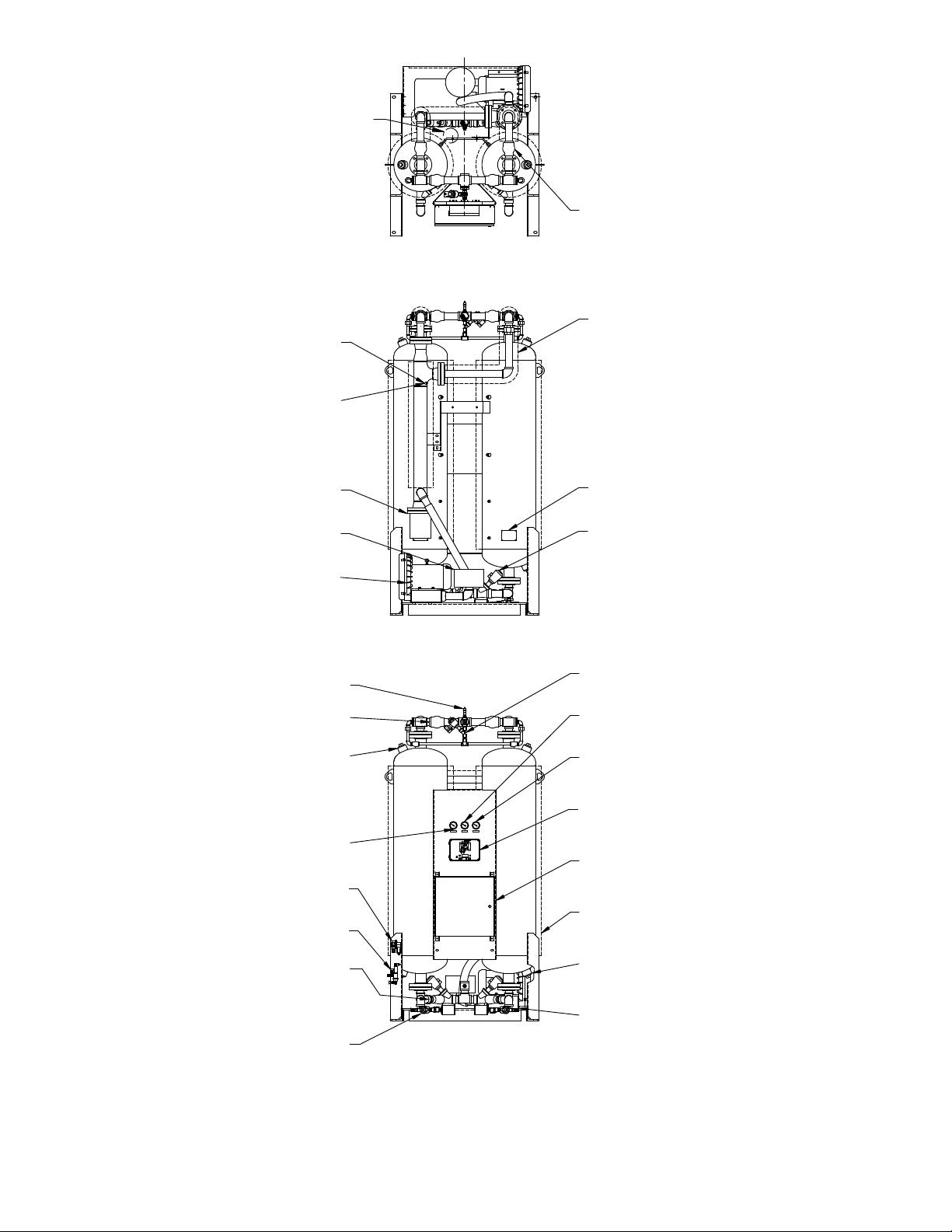
FRONT VIEW
REAR VIEW
PURGE
PRESSURE GAUGE
OUTLET CHECK VALVE
LEFT TOWER
PRESSURE GAUGE
TOWER PURGE
EXHAUST VALVE
PRESSURE REGULATOR
& PILOT AIR FILTER
DEWPOINTER
(OPTIONAL)
DESICCANT
FILL PORT
DESICCANT
DRAIN PORT
TOWER
INSULATION
(OPTIONAL)
RIGHT TOWER
PRESSURE GAUGE
HIGH TENSION
ENCLOSURE
CONTROL
ENCLOSURE
ENERGY MANAGEMENT
SENSOR LOCATION
(OPTIONAL)
ASME RELIEF VALVE
PURGE INLET
CHECK VALVE
HEATER TEMP
THERMOCOUPLE
(CENTER END IN PIPE)
(OPPOSITE SIDE)
HOT PIPE INSULATION
PURGE
HEATER WITH
INSULATION
HEATER OVERTEMP RTD
TOWER INLET
VALVE
ASME CODE TAG
TOP VIEW
TOWER BLOW-
DOWN VALVE
REPRESS VALVE
PURGE SUCTION
FILTER SILENCER
PURGE BLOWER
AND MOTOR
TOWER
DEPRESS VALVE
Figure 3
General Layout Drawing
(Models 500 through 600)
9
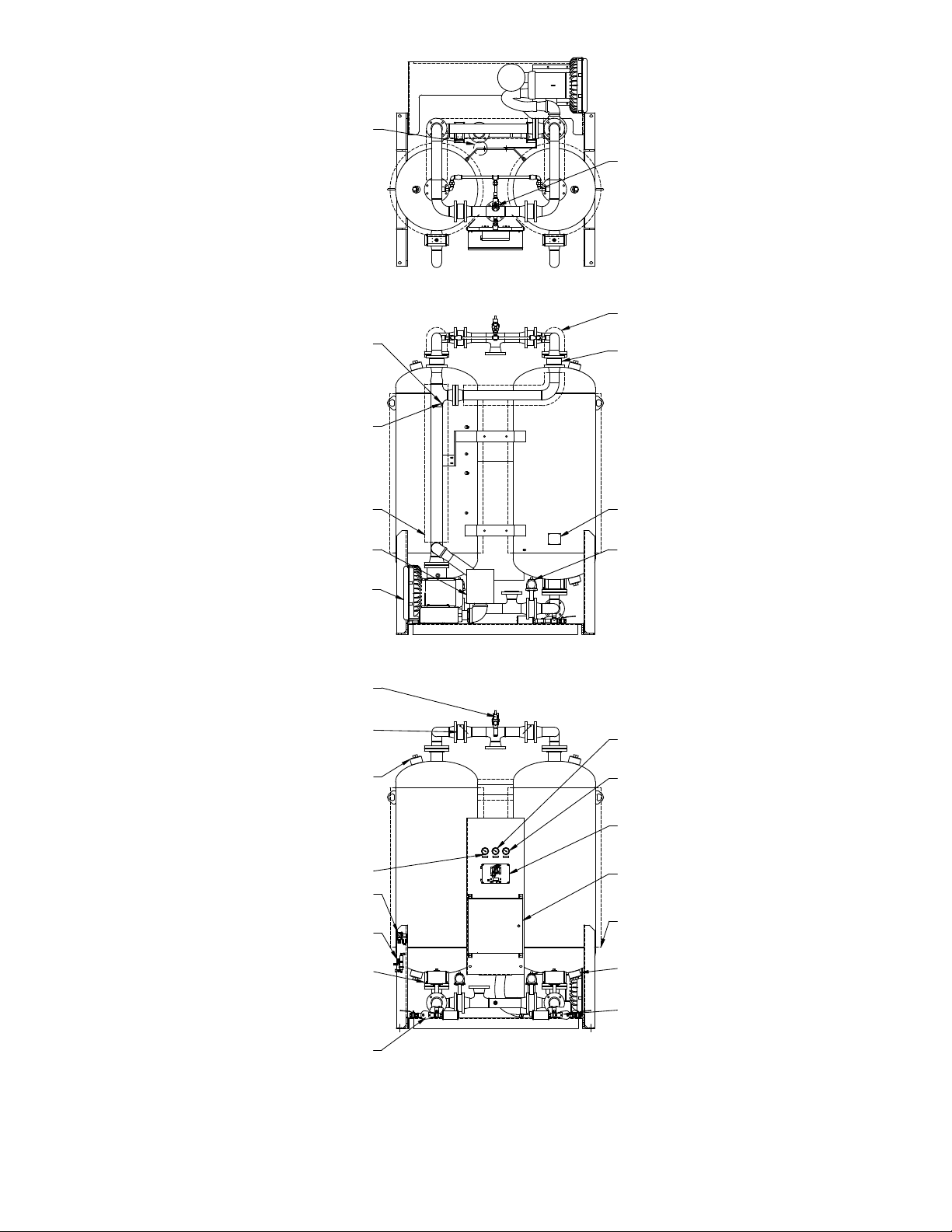
Figure 3a
General Layout Drawing
(Models 750 through 2600)
FRONT VIEW
REAR VIEW
TOP VIEW
ASME RELIEF VALVE
LEFT TOWER
PRESSURE GAUGE
PRESSURE REGULATOR
& PILOT AIR FILTER
OUTLET CHECK VALVE
TOWER PURGE
EXHAUST VALVE
DEWPOINTER
(OPTIONAL)
DESICCANT
FILL PORT
TOWER BLOW-
DOWN VALVE
DESICCANT
DRAIN PORT
TOWER
INSULATION
(OPTIONAL)
PURGE
PRESSURE GAUGE
RIGHT TOWER
PRESSURE GAUGE
HIGH TENSION
ENCLOSURE
CONTROL
ENCLOSURE
ENERGY MANAGEMENT
SENSOR LOCATION (OPTIONAL)
HEATER TEMP
THERMOCOUPLE
(CENTER END IN PIPE)
(OPPOSITE SIDE)
HOT PIPE INSULATION
PURGE
HEATER WITH
INSULATION
HEATER OVERTEMP RTD
ASME CODE TAG
PURGE INLET CHECK VALVE
CHAMBER INLET
VALVE
PURGE SUCTION
FILTER SILENCER
PURGE BLOWER
AND MOTOR
REPRESS VALVE
TOWER
DEPRESS VALVE
10
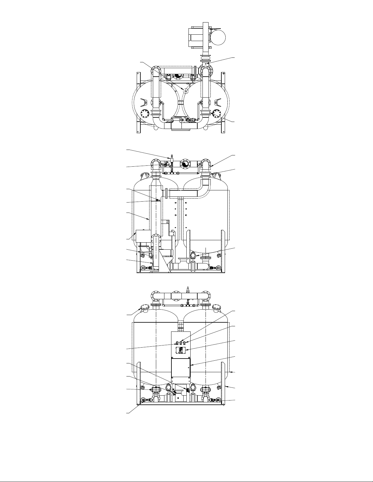
Figure 3b
General Layout Drawing
(Models 3200 through 4300)
FRONT VIEW
REAR VIEW
TOP VIEW
PRESSURE REGULATOR
& PILOT AIR FILTER
DEWPOINTER
(OPTIONAL)
LEFT TOWER
PRESSURE GAUGE
TOWER PURGE
EXHAUST VALVE
DESICCANT
FILL PORT
TOWER
DEPRESS VALVE
DESICCANT
DRAIN PORT
TOWER INSULATION
(OPTIONAL)
PURGE PRESSURE
GAUGE
RIGHT TOWER
PRESSURE GAUGE
HIGH TENSION
ENCLOSURE
CONTROL
ENCLOSURE
ASME RELIEF VALVE
HEATER
OVERTEMP RTD
HEATER TEMP
THERMOCOUPLE
(CENTER END
IN PIPE)
(OPPOSITE SIDE)
PURGE
HEATER WITH
INSULATION
TOWER
INLET VALVE
PURGE INLET
CHECK VALVE
HOT PIPE
INSULATION
REPRESS
VALVE
OUTLET CHECK VALVE
PURGE SUCTION
FILTER SILENCER
PURGE BLOWER
THROTTLING VALVE
PURGE BLOWER
AND MOTOR
ENERGY MANAGEMENT
SENSOR LOCATION
(OPTIONAL)
TOWER BLOW-
DOWN VALVE
HEATER INLET
TEMPERATURE SWITCH

11
6.0 Operation
6.1 Controls
A solid-state controller controls valve and heater opera-
tion, monitors all critical operating conditions, and indi-
cates operating status on a 2-line LCD display operator
interface. The controller receives input data from pres-
sure switches, temperature sensors and the operator
interface. The operator interface displays information
about the dryer operating status and is used to change
the dryer operating mode.
6.2 Operating Modes
6.2.1 Automatic and Manual Advance
The drying and regeneration cycles are divided into
discrete steps. The operator selects either one of the
automatic advance modes (Energy Management, Dew
Point Control, or Fixed Cycle) or manual advance mode
(Test Cycle) through the operator interface.
Selecting any of the automatic advance modes enables
a timer in the controller to advance the program step-by-
step according to the programmed schedule.
Setting up the controller for manual advance disables the
timer and the operator can advance the program one step
at a time. This mode is used for diagnostic purposes.
6.2.2 Fixed, Energy Management or Dew Point
Control Operation
The operator interface is used to select either Fixed,
Energy Management or Dew Point Control operation. In
Fixed Cycle operation, each tower is on-line (drying) for a
xed time period regardless of the operating conditions.
In Energy Management or Dew Point Control operation,
a tower remains on-line until the desiccant bed has been
fully utilized. For lower than designed moisture loads,
this results in longer drying cycles, longer time between
regenerations and, therefore lower energy consumption.
Energy Management or Dew Point Control operation
are optional features.
6.3 Operating Sequence Description
1. Left Tower Drying – Right Tower Regenerating
At the start of the Left Tower Drying cycle, Left Inlet
Valve V1 opens, Right Inlet Valve V2 closes to iso-
late the two towers. Wet, compressed air ows up
through the left tower where it is dried. The dry air
exits the dryer through the Left Outlet Check Valve
V7.
Next, the Right Depressurization Valve V10 is
opened and the right tower is slowly depressurized.
Air exits through exhaust mufer M2.
After the right tower has depressurized, the Right
Purge Valve V4 is opened and the Blower Mand
Heater H1 are energized. The heated air ows
through the Right Purge Check Valve V6, down
through the right tower, and exits through the Right
Purge Valve V4. The Blower intake air is ltered
to keep dust and dirt from entering the dryer. The
Blower Mand Heater H1 are de-energized when
the temperature at the bottom of the right tower,
as sensed by the Right Tower Temperature Sensor
RTD2, reaches the Heat Termination set point. This
indicates that the bed has been fully heated.
NOTE: Blower will continue to run briey at the end
of the Heating Step to sweep residual heat from the
heater.
The Repressurization Valve V11 is opened. A portion
of the dry air from the left tower now ows through
Repressurization Valve V11. This air is throttled to
near atmospheric pressure by Repressurization/
Sweep Orice O2. The dry, low pressure air ows
down through the right tower cooling the desiccant
bed, and exits through the Right Tower Purge Ex-
haust Valve V4.
The Cooling Step continues until:
a) the right tower bed temperature falls to 150°F
or,
b) it is time to repressurize the right tower,
whichever occurs rst.
NOTE: In xed cycle, the bed will normally be
partially cooled because the repressurization step
will occur before the bed temperature can fall to
150°F.
NOTE: In Energy Management or Dew Point Con-
trol, as the drying time extends beyond 4 hours,
additional cooling time becomes available thus the
cooling step will frequently terminate based on tem-
perature providing complete bed cooling.
At the end of the Cooling Step, the Right Tower Purge
Exhaust Valve V4 is closed. The right tower slowly
repressurizes to full line pressure and is ready to go
back on-line.
NOTE: Bed cooling can be disabled by moving JP4
to the “ON” position.
2. Right Tower Drying – Left Tower Regenerating
At the start of the Right Tower Drying cycle, Right
Inlet Valve V2 opens, Left Inlet Valve V1 closes to
isolate the two towers. Wet, compressed air ows
up through the right tower where it is dried. The dry
air exits the dryer through the Right Outlet Check
Valve V8.
Next, the Left Depressurization Valve V9 is opened
and the left tower is slowly depressurized. Air exits
through exhaust mufer M1.
12
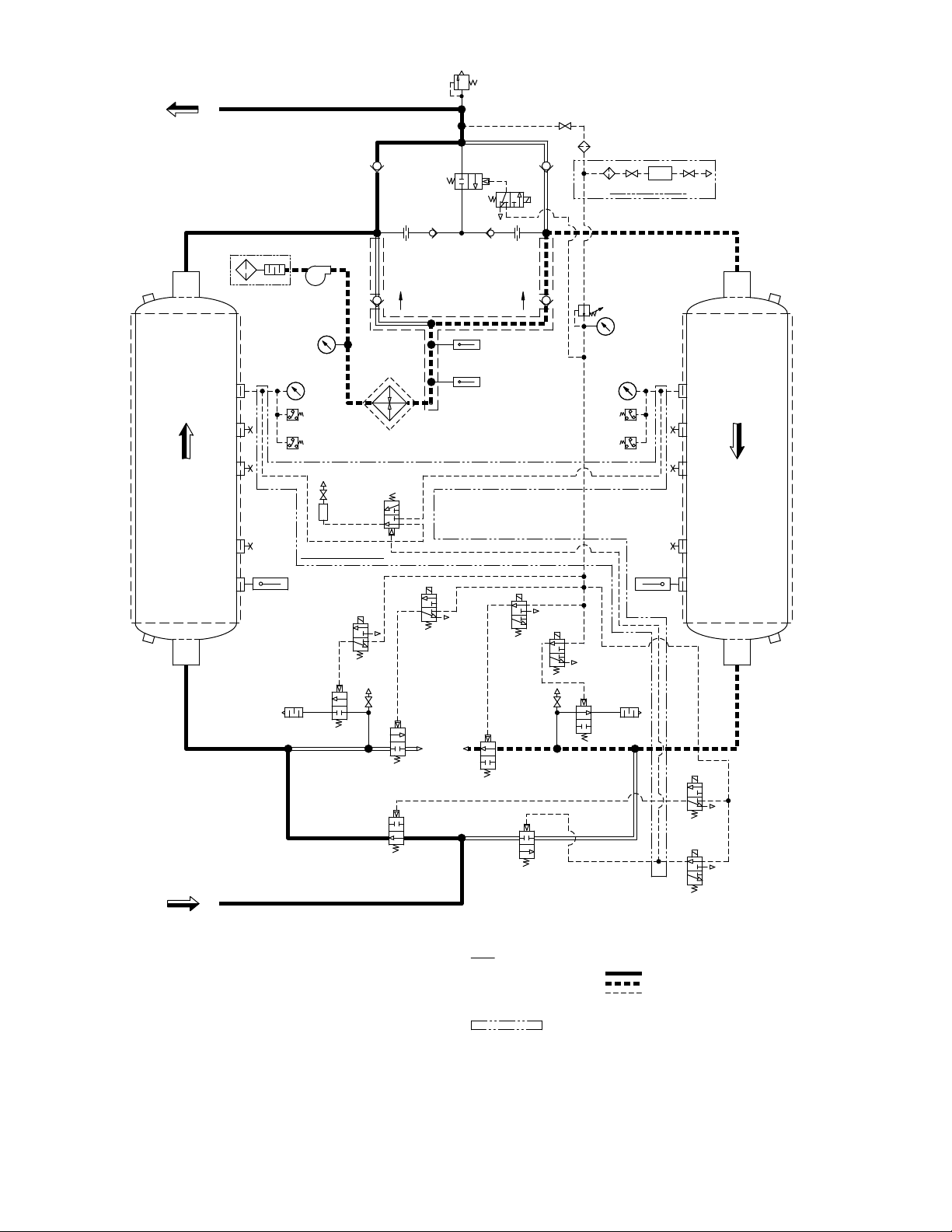
Figure 4
Sequence of Operation — Fixed Cycle Operation
Left Chamber Drying – Right Chamber Regenerating (shown)
(continued on next page)
RIGHT
WET GAS
INLET
DRY GAS
OUTLET
RTD 3
3
1
2
ENERGY MGMT OPTION
EXH.
1TC
SET @ 370°F
LEFT
CHAMBERCHAMBER
REGENDRYING
SOL 'C' SOL 'D' RTD 2
100 PSIG
SET AT
V7 V8
V6V5
V4
V3
SET @ 165 PSIG
SOLENOID VALVES 'B', 'D', & 'G' ARE SHOWN ENERGIZED,
SYMBOLS ARE PER ANSI Y32.10 "GRAPHIC SYMBOLS FOR FLUID POWER DIAGRAMS."
SOLENOID VALVES 'A', 'C', 'E', & 'F' ARE SHOWN DE-ENERGIZED.
AS SHOWN FLOW DIRECTION IS:
INDICATES OPTION
3.
2.
1.
PILOT GAS LINE
RIGHT CHAMBER REGEN
LEFT CHAMBER DRYING
NOTES
4.
DPA
DEWPOINTER OPTION
SOL 'B'
SOL 'A'
(RTD4/HS1)
M
SOL 'E'
V11
V12 V13
V9
M1
SOL 'F'
M2
RTD 1
V1 V2
SET @ 650°F
SOL 'G'
V10
SET @ 176°F SET @ 176°F
2PS
SET @
45 PSIG
SET @
5 PSIG 4PS
1PS
3PS
45 PSIG
SET @
SET @
5 PSIG
V14
F2
F1 O1 O2
PR&G
PI3
PI1 PI2
H1
BD1 BD2

13
After the left tower has depressurized, the Left Purge
Valve V3 is opened and the Blower Mand Heater
H1 are energized. The heated air ows through the
Left Purge Check Valve V5, down through the left
tower, and exits through the Left Purge Valve V3.
The Blower intake air is ltered to keep dust and dirt
from entering the dryer. The Blower Mand Heater
H1 are de-energized when the temperature at the
bottom of the left tower, as sensed by the Left Tower
Temperature Sensor RTD1, reaches the Heat Ter-
mination set point. This indicates that the bed has
been fully heated.
The Repressurization Valve V11 is opened. A portion
of the dry air from the right tower now ows through
Repressurization Valve V11. This air is throttled to
near atmospheric pressure by Repressurization/
Sweep Orice O1. The dry, low pressure air ows
down through the left tower cooling the desiccant
bed, and exits through the Left Tower Purge Exhaust
Valve V3.
The Cooling Step continues until:
a) the left tower bed temperature falls to 150°F
or,
b) it is time to repressurize the left tower,
whichever occurs rst.
NOTE: In xed cycle, the bed will normally be
partially cooled because the repressurization step
will occur before the bed temperature can fall to
150°F.
NOTE: In Energy Management or Dew Point Con-
trol, as the drying time extends beyond 4 hours,
additional cooling time becomes available thus the
cooling step will frequently terminate based on tem-
perature providing complete bed cooling.
At the end of the Cooling Step, the Left Tower Purge
Exhaust Valve V3 is closed. The left tower slowly
repressurizes to full line pressure and is ready to go
back on-line.
NOTE: Bed cooling can be disabled by moving JP4
to the “ON” position.
6.3.1 Energy Management Control (optional)
Operation of the Energy Management Control cycle is
identical to the xed cycle except the cycle is extended
until the desiccant bed in the on-line tower has been fully
utilized. The off-line tower is regenerated and remains
in a stand-by mode after being repressurized.
Figure 5 shows the air sampling system for the Energy
Management System – EMS option. A 3-way pilot valve
directs an air sample from the drying tower to the EMS
sensor. The EMS sensor detects the relative humidity
and temperature of the air sample. The air sample then
exhausts to atmosphere. The drying tower remains on-
line until the moisture front arrives at the sensor.
P
EMS
LEFT
TOWER
RIGHT
TOWER
Figure 5
Optional Moisture Sensing
Energy Management System (EMS)

14
6.4 Control Board Jumpers
In the upper left hand corner of the control board there
are eight two-pin jumpers labeled JP1 through JP8. Only
six of the eight jumper pairs are utilized. Pairs JP7-JP8
are used for factory settings and testing. NOTE: Do
not install jumpers in the ON position on pairs JP7
through JP8. The jumper is a removable bridge that is
used to make or break continuity between two pins that
form a pair. When installed in the ON position, the jumper
is place on both pins of the pair and continuity between
the pins is established. When installed in the OFF posi-
tion, the jumper is removed or stored on a single pin and
continuity is broken. Jumper functions are as follows:
1. JP1 – Dryer Type
Jumper JP1 is used to select the dryer type congu-
ration. It is installed in the ON position for Blower
Purge dryer conguration.
2. JP2 – Energy Management
Jumper JP2 is installed in the ON position when an
Energy Management sensor is installed. The jumper
is installed in the OFF position when no Energy
Management sensor is installed.
3. JP3 – Dew Point Transmitter
Jumper JP3 is installed in the ON position when a
Dew Point Transmitter is installed. The jumper is
installed in the OFF position when no Dew Point
Transmitter is installed.
NOTE: “Energy Management” can co-exist with the
dew point transmitter option. Dryer control based
on the ENERGY MANAGEMENT or DEWPOINT
CONTROL is selected on Screen 1 of the Set Up
Mode.
If DEWPOINT CONTROL is not selected then the
dew point signal does not control the dryer cycle but
still serves a monitoring and alarm function.
4. JP4 – Cooling Cycle
Jumper JP4 is installed in the ON position to disable
the Cooling Cycle. The jumper is installed in the OFF
position to enable a Cooling Cycle.
5. JP5 – Switching Failure
Jumper JP5 is installed in the ON position to enable
Switching Failure. The jumper is installed in the OFF
position if Switching Failure is disabled.
6. JP6 – Common Alarm
Jumper JP6 is installed in the OFF position to en-
able both the dryer fault alarms and service alarms
to activate the common alarm. This is the default
conguration. Install jumper JP6 in the ON position
if the common alarm is to activated by a dryer fault
alarm only.
NOTE: Jumpers JP7 and JP8 are used by the fac-
tory during nal inspection to download language
text and to enable ‘factory’ set-up screens.
7. JP7 – Download Language Text
Jumper JP7 is factory installed in the OFF position
to disable Language Text download. The jumper is
installed in the ON position to allow for language text
download due to either language corrections or new
language installation.
8. JP8 – Set Up
Jumper JP8 is factory installed in the OFF position
to disable access to “factory” set up screens. The
jumper is installed in the ON position during nal
inspection at the factory to set controller to match
customer requirements.
6.5 Operator Interface
Refer to Figure 6 , Front Panel Overlay for information
regarding the location and function of the LEDs, switches,
and text display.
6.5.1 Front Panel LED’s
• Power On - green
• Alarm - red
• Service / Maintenance reminder - amber
• Filters (pre, after, and pilot) service / maintenance
reminders - amber
• Inlet switching and purge / repressurization valve sta-
tus (On = valve open; Off = valve closed) - green
• Left and right tower status (heating) - amber
• Left and right tower status (drying) - green
• Left and right tower pressure switch status (On =
switch closed; Off = switch open) - green
6.5.2 Front Panel Switches
The front panel contains four momentary-contact push-
button switches. Refer to Figure 6, Front Panel Overlay
for the appropriate icon associated with each switch.
Pushing on the overlay icon actuates the switch.
Data Display Switch
This switch is used to step through the display
screens.
Select Switch
This button is located to the left of the text display window.
Refer to the Front Panel Operation Section for additional
information.
ENTER Switch
This button is located to the right of the text display
window. Refer to the Front Panel Operation Section for
additional information.
Alarm Reset Switch
This button is normally used to reset an alarm or service
reminder. Refer to the Front Panel Operation Section
for additional information.

15
Left Tower Drying LED
Left Purge Valve LED
On=valve open
Off=valve closed
Left Inlet Valve LED
On=valve open
Off=valve closed
Left Tower
Heating LED
Filter Service /
Maintenance LED
Vacuum Fluorescent
Text Display
Select switch
Power On LED
Data Display Switch
Communications Icon
Filter Service /
Maintenance LED
Filter Service /
Maintenance LED
Right Tower Pressure
Switch LED:
On=Tower pressurized
Right Tower Drying LED
Right Purge Valve LED
On=valve open
Off=valve closed
Right Tower
Heating LED
Right Inlet Valve LED
On=valve open
Off=valve closed
Enter Switch
Maintenance / Service
Reminder LED
Alarm LED
Reset Switch for Alarm
Left Tower Pressure
Switch LED:
On=Tower Pressurized
RS232
Figure 6
Front Panel Overlay
6.5.3 Front Panel Operation
1. There are five operating modes for the Heated
Desiccant Dryer Control.
a. Program Mode
b. Setup Mode
c. Alarm & Service Mode
d. Display Mode
e. Test Mode
2. Each Mode is described below.
6.5.4 Program Mode
1. Press and hold and for 3 seconds to enter
Program Mode.
2. Program Mode is comprised of the screens that are
described below.
3. There are three (3) ways to exit Program Mode.
a. Press after making the selection in the nal
screen.
b. At any screen, press and hold for 3 sec-
onds.
c. The controller automatically exits Program Mode
if no button is pressed within 60 seconds.
4. Upon exiting Program Mode the controller will switch
to Display Mode.
Screen 1: Select the Language
ENGLISH
1. Press to scroll through the choices: ENGLISH,
FRANCAIS and ESPANOL.
2. When nished, press to save the selection and
move to next screen.
Screen 2: Select the Service Level
SERVICE LEVEL
NORMAL
1. Press to toggle between NORMAL and
SEVERE.
a. NORMAL Service Intervals are:
i. 4000 hours for lters
ii. 8000 hours for desiccant
iii. 8000 hours for valves

16
b. SEVERE Service Intervals are:
i. 2000 hours for lters
ii. 4000 hours for desiccant
iii. 4000 hours for valves
2. When nished, press to save the selection and
move to next screen.
Screen 3: Reset the Timer for Filter Service
FILTER SERVICE
RESET? NO
1. Press to toggle between NO and YES.
2. When finished, press to acknowledge the
selection and move to next screen.
Screen 4: Reset the Timer for Desiccant Service
DESICCANT SERVICE
RESET? NO
1. Press to toggle between NO and YES.
2. When finished, press to acknowledge the
selection and move to next screen.
Screen 5: Reset the Timer for Valve Service
VALVE SERVICE
RESET? NO
1. Press to toggle between NO and YES.
2. When nished, press to acknowledge the selec-
tion and move to next screen.
Screen 6: Set Alarm Point for the Dew Point
Sensor (This feature is only active when
JP3 is “on”)
DEWPOINT ALARM
±XX°C ±XXX°F
XX MIN SW DELAY
1. Press to increment the setting to the desired
value.
a. Standard set point is
-20°C -4°F
.
b. The allowable range of values is from
-80°C -112°F
to
+10°C +50°F
in 5°C/9°F
increments.
2. When nished, press to acknowledge the se-
lection and scroll to the switchover delay set point
screen.
a. Standard set point is
60 MIN
.
b. The allowable range of values are
30 to 120 MIN
in 10 minute increments.
3. When nished, press to acknowledge the selec-
tion and move to next screen. Exit Program Mode
when there are no more active screens to display.
Screen 7: Set Point for Dew Point Demand Control
(This feature is only active when JP3 is “on”)
DPNT CNTL SETPT
±XX°C ±XXX°F
1. Press to increment the setting to the desired
value.
a. Standard set point is
-30°C -22°F
.
b. The allowable range of values is from
-80°C -112°F
to
+10°C +50°F
in 5°C/9°F
increments.
NOTE: Must be set “drier” than Dew Point Sensor
Alarm Set Point (screen 6).
2. When finished, press to acknowledge the
selection and exit the Program Mode.
Screen 8: Set the Heat Termination Set Point
HEAT TERM SET-PT
XX°C XXX°F
1. Press to increment the setting to the desired
temperature value.
a. Refer to P&ID diagrams in the back of this manual
for Heat Termination set points (see set point
values for RTD1 and RTD2).
b. The allowable range of values are:
60° - 160°C 140° - 320°F
in 10°C increments.
2. When nished, press to acknowledge the selec-
tion and move to next screen. Exit Program Mode
when there are no more active screens to display.
Screen 9: Set the Sweep Termination Set Point
SWEEP TERM SET-PT
XX°C XXX°F
1. Press to increment the setting to the desired
temperature value.
The allowable range of values are:
48° - 60°C 118° - 150°F
in 2°C increments.
2. When nished, press to acknowledge the selec-
tion and move to next screen. Exit Program Mode
when there are no more active screens to display.
Screen 10: Set Points for Energy Management
(This feature is only active when JP2 is “on”)
ENRGY MGMT SETPT
XX%RH
XX MBAR .XXX PSI
1. Press to increment the setting to the desired
maximum RH value.
a. Factory set point is
60%RH
. The factory setting
should not require adjustment.
b. The allowable range of values are
20 to 80%RH
in 5% increments.

17
2. When nished, press to acknowledge the selec-
tion and scroll to the pressure set point screen.
3. Press to increment the setting to the desired
maximum vapor pressure value.
a. Standard set point for a -40°F dew point dryer
is
16 MBAR (0.232 PSI)
.
NOTE: Standard set point for a -100°F dew point
dryer
is 4 MBAR (0.058 PSI) .
b. The allowable range of values
is
3 to 34 MBAR (0.044 to 0.493 PSI) in
1 MBAR
increments.
c. This setting may be eld adjusted to increase or
decrease the outlet dew point at tower switch-
over.
4. When nished, press to acknowledge the selec-
tion and move to next screen.
Screen 11: Set Points for High Humidity Alarm
(This feature is only active when JP2 is “on”)
HIGH HUMIDITY
XX%RH
XX MBAR .XXX PSI
XX MIN SW DELAY
1
. Press to increment the setting to the desired
maximum RH value.
a. Factory set point is
75%RH
. The factory setting
should not require adjustment.
b. The allowable range of values are
20 TO 80%RH
in 5% increments.
NOTE: Value must be set above Energy Manage-
ment Maximum RH Value Set Point (screen 9).
2. When nished, press to acknowledge the selec-
tion and scroll to the pressure set point screen.
3. Press to increment the setting to the desired
maximum vapor pressure value.
a. Factory set point for a -40°F dew point dryer is
24 MBAR (0.348 PSI)
.
NOTE: Factory set point for a -100°F dew point
dryer is
5 MBAR (0.073 PSI)
.
b. The allowable range of values is
3 to 34 MBAR (0.044 to 0.493 PSI)
in 1 MBAR incre-
ments.
NOTE: Value must be set above Energy Man-
agement Maximum Vapor Pressure Set Point
(screen 9).
4. When nished, press to acknowledge the se-
lection and scroll to the switchover delay set point
screen.
a. Factory set point is
60 MIN.
.
b. The allowable range of values are
30 to 120 MIN
in 10 minute increments.
5. When nished, press to acknowledge the selec-
tion and move to next screen. Exit Program Mode
when there are no more active screens to display.
6.5.5 Setup Mode
1. Press and hold for 3 seconds to enter Setup
Mode.
2. Setup Mode is comprised of the screens that are
described below.
3. There are two ways to exit Setup Mode.
a.
Press after making the selection in Screen 1.
b. The controller automatically exits Setup Mode if
no button is pressed with 60 seconds.
4. One of two things will happen upon exiting Setup
Mode.
a. The controller will switch to Display Mode if
ENERGY MANAGEMNT, FIXED CYCLE or
DEWPOINT CONTROL is selected.
b. The controller will switch to Test Mode if TEST
CYCLE is selected.
Screen 1: Select the Cycle Type
CYCLE TYPE
ENERGY MANAGEMNT
1. Press to scroll through the choices:
a. ENERGY MANAGEMNT (displayed only when
JP2 is in the ON position)
b. DEWPOINT CONTROL (displayed only when JP3
is in the ON position)
c. FIXED CYCLE
d. MANUAL CYCLE
2. When nished, press to save the selection and
exit the Setup Mode.

18
6.5.6 Alarm & Service Mode
1. Alarm & Service Mode is active when the controller
is in Display Mode. It is not active in Program Mode,
Setup Mode, or Test Mode.
2. Local alarm consists of a blinking alarm LED and an
alarm message display.
3. Alarm messages have priority over Service
messages. Service messages have priority over
Display Messages.
4. After an alarm condition has been corrected, if:
a. Alarm is “self-clearing” then,
i. The alarm LED stops blinking (LED on); the
alarm message continues to be displayed.
ii. The alarm reset button must be depressed to
clear the alarm LED (LED off) and the alarm
message.
b. Alarm must be manually reset, then:
i. The alarm LED continues to blink and the
alarm message continues to be displayed.
ii. The alarm reset button must be depressed
to:
1. Clear the alarm LED (LED off)
2. Clear the alarm message and
3. Restart the dryer cycle.
5. When an alarm condition has not been corrected
and the “alarm reset” button is pressed, the alarm
will not clear except as follows:
a. The alarm conditions will clear for 5 seconds,
then reappear if the alarm condition persists, this
applies to the following alarms:
i. Heater: High Inlet Temperature.
ii. Heater: Low Temperature
iii. Humidity Sensor: High Humidity Alarm
iv. Humidity Sensor: Under-Range or Over-
Range Alarm
v. Dew Point Sensor: High Dew Point Alarm
vi. Dew Point Sensor: Under-Range or Over-
Range Alarm
6. There are three alarms for each tower that are
triggered by the tower pressure switches. These
alarms can occur in any operating mode (Manual,
Fixed, Energy Management, or Dew Point Demand
Cycle).
Following is a brief description of each alarm.
a. Left or Right tower, drying, low pressure
i. Drying tower pressure switch is open during
the drying cycle.
b. Left or Right tower, regenerating, high pressure
i. Regenerating tower pressure switch is closed
while purge valve is open (after an initial time
delay).
c. Left or Right tower, regenerating, low pressure
i. Regenerating tower pressure switch is open
at the end of the regenerating cycle.
d. On alarm condition, the blower and heater are
de-energize, the cycle sequence is stopped, a
local alarm is displayed and the common alarm
relay is de-energized.
e. These alarms are self-clearing.
7. Heater High Inlet Temperature
a. Model sizes 3200, 3600 and 4300 are equipped
with a temperature switch located in the piping
between the blower and heater.
b. If during the Heat Cycle this temperature switch
opens, indicating a rise in temperature above
the factory setting (refer to Electrical Schematic
drawings at the back of this manual for set point),
an alarm is activated.
c. On alarm condition, the blower and heater are
de-energized, the cycle sequence is stopped, a
local alarm is displayed and the common alarm
relay is de-energized.
d. This alarm must be manually reset.
8. The dryer is equipped with RTD temperature sensors.
There are out of range alarms for each.
a. The standard left tower, right tower, and heater
RTDs (RTD1, RTD2, RTD3) are scaled from
-20°F(-28°C) to 890°F (477°C), “Out of Range”
conditions are as follows:
i. Over-range - temperature above 850°F
(454°C)
ii. Under-range - temperature below -20°F
(-28°C)
iii. NOTE: The controller will annunciate a
“Heater Overtemperature” alarm in lieu of an
“Over Range” alarm when the heater sensor
is disconnected.
b. The Energy Management RTD4 is scaled from
-20°F(-28°C) to 429°F(220°C), “Out of Range”
conditions are as follows:
i. Over-range - temperatures above 400°F
(204°C)
ii. Under-range - temperatures below -20°F (-
28°C)
c. On alarm condition, a local alarm is displayed and
the common alarm relay is de-energized.
d. Over-range and Under-range alarms are self-
clearing.
This manual suits for next models
13
Table of contents
Other SPX Dehumidifier manuals

SPX
SPX HPD Series User manual

SPX
SPX Hankison HPRP Series User manual

SPX
SPX Hankison HPRplus Series User manual

SPX
SPX HANKISON HES Series User manual

SPX
SPX RDH-HP Series User manual

SPX
SPX HANKISON HIT Series User manual

SPX
SPX DELAIR QD 90 User manual

SPX
SPX HCD Series User manual

SPX
SPX Hankison GCU Series User manual


