SPX Hankison HPRP Series User manual

1
HPRP Series
Refrigerated Type Compressed Air Dryers
Models: HPRP100, HPRP125, HPRP150, HPRP200, HPRP250, HPRP300, HPRP400, HPRP500, HPRP600, HPRP750
FORM NO.: 5002730 REVISION: 01/2012 READ AND UNDERSTAND THIS MANUAL PRIOR TO OPERATING OR SERVICING THIS PRODUCT.
INSTRUCTION MANUAL
2
CONTENTS
GENERAL SAFETY INFORMATION .................................... 2
RECEIVING, MOVING, AND UNPACKING .......................... 2
1.0 INSTALLATION........................................................... 3
2.0 OPERATION.............................................................. 5
3.0 MAINTENANCE ........................................................ 9
SIZING.............................................................................. 9
ENGINEERING DATA
Models 100-250.......................................................... 10
Models 300-750.......................................................... 11
WIRING DIAGRAM
Model 100: 120/230 VAC........................................... 12
Models 125-150: 120/230 VAC.................................. 13
Models 200-600: 460 VAC ......................................... 14-15
Model 750: 460 VAC .................................................. 16-17
Models 200-750, 575-460/3/60 Transformer Pack ... 18
DIMENSIONS / WEIGHTS.................................................. 19
TROUBLESHOOTING GUIDE
Models 100-150.......................................................... 20
Models 200-750.......................................................... 21
PARTS LIST....................................................................... 22
WARRANTY ..................................................................... 23
GENERAL SAFETY INFORMATION
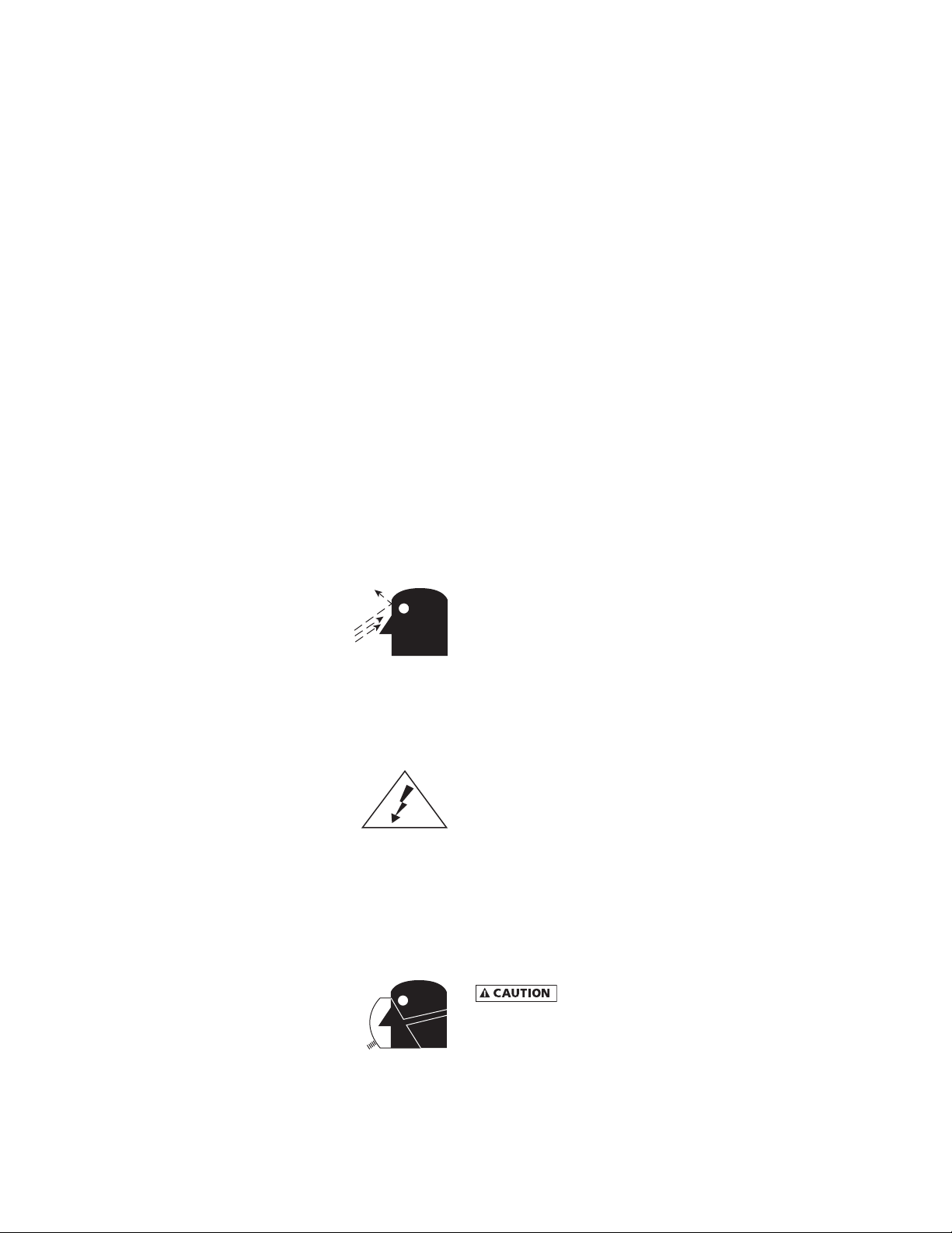
1. PRESSURIZED DEVICES:
This equipment is a pressure containing
device.
• Donotexceedmaximumoperating
pressure as shown on equipment
serial number tag.
• Make sure equipment is depressurized before
working on or disassembling it for service.
2. ELECTRICAL:
This equipment requires electricity to
operate.
• Installequipmentincompliancewith
all applicable electrical codes.
• Standard equipment is supplied with electrical
enclosuresnotintendedforinstallationinhazardous
environments.
• Disconnect power supply to equipment when
performing any electrical service work.
3. BREATHING AIR:
• Air treated by this equipment may
not be suitable for breathing without
further purification.
Refer to applicable standards and
specifications for the requirements
for breathing quality air.
RECEIVING, MOVING, AND UNPACKING
A. RECEIVING
This shipment has been thoroughly checked, packed and
inspected before leaving our plant. It was received in
good condition by the carrier and was so acknowledged.
Check for Visible Loss or Damage. If this shipment shows
evidence of loss or damage at time of delivery to you,
insist that a notation of this loss or damage be made on
the delivery receipt by the carrier’s agent.
B. UNPACKING
Check for Concealed Loss or Damage. When a shipment
has been delivered to you in apparent good order, but
concealed damage is found upon unpacking, notify the
carrier immediately and insist on his agent inspecting
the shipment. Concealed damage claims are not our
responsibility as our terms are F.O.B. point of shipment.
C. MOVING
In moving or transporting dryer, do not tip dryer onto
its side.
D. STORAGE/SHUT DOWN
Dryer should not be stored outside (either
packedorunpacked)orexposedtotheweather.Damage
to electrical and control components may result.
IMPORTANT: WATER-COOLED UNITS - If unit is shut down
belowfreezingtemperatures,thewater-cooledcondenser
mayfreezeandcausepermanentdamage.Condensermust
be drained when the unit is shut down.
IMPORTANT: Do not store dryer in temperatures above
130°F, 54.4°C.

3
IMPORTANT: READ PRIOR TO STARTING THIS EQUIPMENT
1.0 INSTALLATION
1.1 Location
A. For typical placement in a compressed air system, see
drawing.
B. Air compressor intake – Locate air compressor so that
contaminants potentially harmful to the dryer (e.g.
ammonia) are not drawn into the air system.
C. Clearances Free air flow
Front 36 inches (914 mm)
Back 6 inches (152 mm)
Sides 36 inches (914 mm)
Service - To facilitate maintenance leave 36 inches
(914 mm) of clearance in front of dryer.
D. Standard units are designed to operate in ambients:
Air-cooled: 40 to 110°F (4 to 43°C).
Water-cooled: 40 to 130°F (4 to 54°C).
E. Installations in altitudes above 4500 feet (1370 meters) –
Dryer is adjusted to operate in altitudes up to 4500 feet
(1370 meters). If dryer is installed in an altitude above
this, and has not been preset at the factory for this
altitude, contact manufacturer’s Service Department.
F. The installation of a exible connection prior to the
dryer is recommended to prevent possible damage from
vibration.
NOTE: Outdoor installation – Standard units are designed
for indoor installation. Contact manufacturer if installing
outdoors.
Aftercooler
Separator
Dryer
Oil Removal
Filter
Compressor
Moisture Separator
Coalescing Filter
(Option)
Float Drain
(Standard)
Condenser
Drain Outlet
Electrical Entry
(230 VAC)
Air Outlet
Air Inlet
Control Panel
Models 100, 125, & 150
Electric Demand Drain (EDD)
3-Way Valve
Moisture Separator
Coalescing Filter
(Option)
Control Panel
RS232 Entry
Electrical Entry
Air Outlet
Air Inlet
Condenser
Drain Outlet
Models 200, 250, 300, 400, 500, 600, & 750
4
1.2 Mounting
Mount the dryer on a level solid surface. Holes are provided
in the dryer base to permanently mount the dryer to the
floor.
1.3 Piping connections
A. Air Inlet - Connect compressed air line from air source
to air inlet. (Reference markings on dryer for air inlet/
outlet connection locations.)
RefertoSerialNumberTagformaximumworking
pressure.Donotexceeddryer’sMaximumWorkingPressure.
NOTE: Install dryer in air system at highest pressure possible
(e.g. before pressure reducing valves).
NOTE: Install dryer at coolest compressed air temperature
possible.Maximuminletcompressedairtemperature:120°F
(49°C).Ifinletairexceedsthistemperature,precooltheair
with an aftercooler.
B. Air Outlet – Connect air outlet to downstream air lines.
C. Bypass piping – If servicing the dryer without
interrupting the air supply is desired, piping should
include inlet and outlet valves and an air bypass valve.
D. Water cooled models – cooling water inlet and outlet
1. Connect cooling water supply to cooling water inlet.
2. Connect cooling water return line to cooling water
outlet connection.
NOTE: Strainer and water regulating valve are supplied on
water cooled models.
1.4 Electrical connections
IMPORTANT: Use copper supply wires only.
A. Dryer is designed to operate on the
voltage, phase, and frequency listed on
the serial number tag.
B. If dryer is supplied with a cord and plug,
install in a receptacle of proper voltage.
C. Electrical entry on larger dryers is through a hole in
the cabinet. It is located on the right side panel when
facing the front of the unit. Connect power source to
terminal strip in electrical enclosure as shown on the
wiring diagram included with the dryer.
NOTE: Refrigeration condensing unit is designed to run
continuously and should NOT be wired to cycle on/off with
the air compressor.
NOTE: ON MODELS 500, 600, and 750, CHECK FOR CORRECT
PHASING OF UNIT. After starting the dryer, if an unusual
noise is heard, or if the discharge line does not get hot, the
refrigeration compressor may be running in the reverse
direction. Immediately stop the dryer, reverse two of the
power leads, restart the dryer, and verify the unusual noise is
corrected and the refrigerant discharge line is hot. FAILURE
TO DO SO MAY DAMAGE THE COMPRESSOR AND VOID THE
WARRANTY.
1.5 Moisture separator
A. Models 100-150:
Separator (and Oil Removal Filter where
applicable) has an internal drain which
automatically discharges condensate.
Models 200-750:
Separator (and Oil Removal Filter where applicable) has
an electronic demand drain (EDD) which automatically
discharges condensate.
NOTE: It may be desirable to pipe the condensate from the
Automatic Drain outlet to a suitable drain.
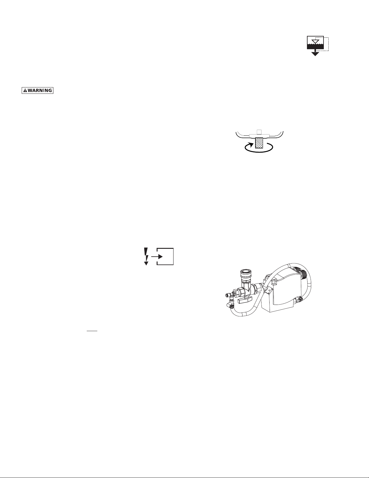
B. Models 100-150:
Separatorhasaknurledttingwithexibledraintubing
attached. Be sure knurled fitting is tightened by turning
counter-clockwise before operating dryer.
TO CLOSE
TURN COUNTERCLOCKWISE
C. Models 200-750
Formanualdraining,convenientdryerdepressurization,
and EDD service, a three-way valve assembly has been
installed at the bottom of the moisture separator (and
cold coalescing filter where applicable). Review the
following for proper drain function:
• Automatic Draining - Valve handle should be
positioned parallel to the valve body (as shown),
with the arrow on the handle pointing toward the
EDD. In this position, condensate will flow from the
bowl to the EDD.
• DrainIsolation (Shutdown)- Valvehandleshall be
turned perpendicular to the valve body (rotate 90°).
In this position, condensate flow is shutoff.
• ManualDraining-Drainvalvehandleshallberotated
slightly past the drain isolation position to allow
throttling through the valve for manual discharge
anddepressuruzation.
• NOTE: The quick disconnect fitting allows removal
of the entire drain assembly. However, the unit
must be depressurized prior to disassembly or
serious injury may occur.
NOTE:Discharge is at system pressure. Drain line should be
anchored.
NOTE:Condensate may contain oil. Comply with applicable
laws concerning proper disposal.

5
1.6 Operation
A. Verify that isolation valves are open. If the drain fails to
discharge after the valve is energized, the electronic
controlcircuitwillrepeatedlyenergizethevalveinan
attempt to clear the discharge port. If, after 60 seconds,
the drain still fails to discharge, the control circuit then
switches to the alarm mode. In this mode the valve is
de-energized and the red alarm light is activated on
the drain and the dryer controller. The valve is then
automaticallyenergizedevery4minutesfor5seconds.
Check the drain operation. Push drain (push-to-test)
button on the Energy Management Monitor control
boardtoenergizedrain.Aowofcondensateand/orair
should be present at the drain outlet. The alarm mode
automatically clears after the drain returns to normal
operation.
B. Condensate enters the reservoir (1) through the inlet
port. When the condensate level in the reservoir covers
the capacitance sensor, an electronic signal is sent to the
solid state countdown processor. The processor delays
the opening of the solenoid valve for a given period
of time. Once the time has elapsed, the solid state
processortransmitsinformationtoenergizethecoilin
the solenoid valve (2). The magnetic force of the coil
causes the solenoid core (3) to move, closing the pilot
air supply line and opening the pilot air exhaust line.
After the pilot air above the diaphragm (4) is vented,
pressure in the reservoir opens the discharge port and
forces the condensate through the discharge port and
outlet piping.
2.0 OPERATION
2.1 Minimum/Maximum operating conditions
A. Maximuminletairpressure:refertodryerserialnumber
tag
B. Minimum inlet air pressure: 30 psig (2.1 kgf/cm
2
)
C. Maximuminletairtemperature:120°F(49°C)
D. Maximumambienttemperature:
Air-cooled models: 110°F (43°C)
Water-cooled models: 130°F (54°C)
E. Minimum ambient temperature: 40°F (4°C)
2.2 Start-up
A. Models 100-150:
Energizecompressorbypositioningtheon/offswitchin
the on (I) position. Compressor on light will illuminate.
On/Off Switch Power-On Light Dewpoint Indicator (Green)
B. Models 200-750:
Energizedryer.Greenpoweronlightwillilluminate.
IMPORTANT:Energizedryerdisconnectswitch(providedby
others, see NEC) 24 hours before refrigeration compressor
is started! Never use the disconnect switch to shutdown
thedryerforaextendedperiodoftime(exceptforrepair).
Failure to follow these instructions may result in a non-
warrantable compressor failure.
NOTE: If there is no power to the control board for a period
of two weeks or more, it may return to the default mode.
C. Program Monitor
Press and hold Program Mode button until Main Menu screen
appears. Use the Up and Down arrow buttons to scroll
through the list of submenu choices. Press Enter button
toviewthesubmenuthatisdisplayed.PressESCtoexitthe
Main Menu and return to Display mode.
1. Language selection
a. Use the ‘Up’ and ‘Down’ arrow buttons to scroll
through the list of languages (choice of 10 available:
English, Deutsch, Francais, Espanol, Italiano, Polski,
Dansk, Dutch, Norsk and Suomi).
b. Press ‘Enter’ button to select the language that is
displayed.
c. Push ‘ESC’ at any time to return to the Main Menu.
2. Setting Date & Time
a. Use the ‘Up’ and ‘Down’ arrow buttons to set minutes
(00 to 59). Press ‘Enter’ to accept new value.
b. Use the ‘Up’ and ‘Down’ arrow buttons to set hours
(00 to 23). Press ‘Enter’ to accept new value.
c. Use the ‘Up’ and ‘Down’ arrow buttons to set year
(00 to 99 representing 2000 to 2099). Press ‘Enter’
to accept new value.
d. Use the ‘Up’ and ‘Down’ arrow buttons to set month
(three letter abbreviation). Press ‘Enter’ to accept
new value.
e. Use the ‘Up’ and ‘Down’ arrow buttons to set day
(01tomaximumforthemonthandyearselected).
Press ‘Enter’ to accept new value.
f. Push ‘ESC’ at any time to return to the Main Menu.
1
2
3
4
6
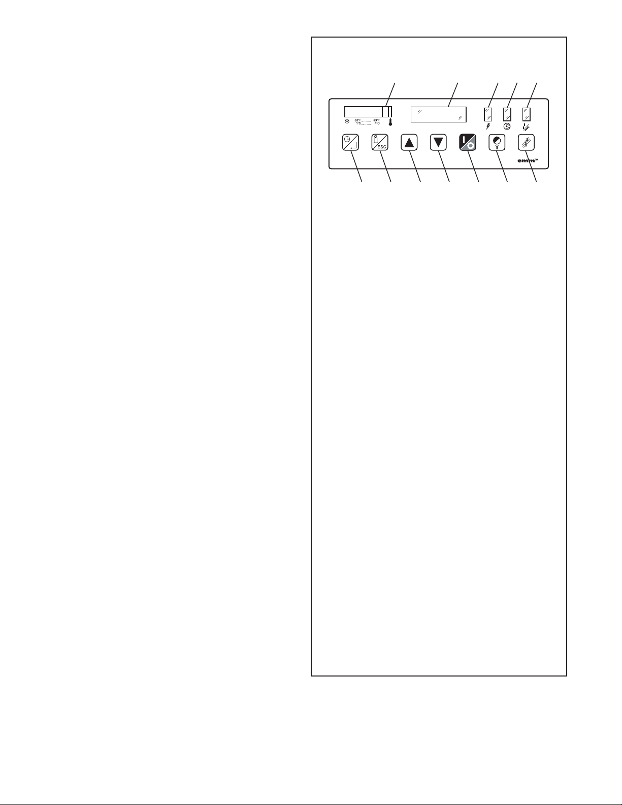
1. Temperature Indicator
2. Operator Interface Display
3. Power-on Light
4. Compressor-on Light
5. Alarm / Service Light
6. Schedule On/Off and Enter Button
a. In display mode: Press to toggle between
SCHEDULE RUNNING and MANUAL OVERRIDE.
b. In program mode:
i. Press to move to a lower level menu.
ii. Press to accept a value that has been edited.
7. Program Mode (i) and Esc
a. In display mode: Press and hold to enter pro-
gram mode.
b. In program mode: Press to move to a higher
level menu.
8. Up Arrow
a. In display mode: No function
b. In program mode:
i. Presstoviewthenextiteminalistorto
increment a variable to a higher value. Press
and hold for accelerated incrementing.
ii. When the top of the list (or highest value) is
displayed, pressing the up button will cause
the display to wrap to the bottom of the list
(or lowest value).
9. Down Arrow
a. In display mode: No function
b. In program mode:
i. Press to view the previous item in a list or to
increment a variable to a lower value. Press
and hold for accelerated incrementing.
ii. When the bottom of the list (or lowest value)
is displayed, pressing the down button will
cause the display to wrap to the top of the
list (or highest value).
10. 1/0: Press at any time to turn the dryer on/off.
11. Drain test: Press at any time to momentarily the
open drains (like the current emm).
12. Reset: Press at any time to clear the alarm/service
message (if shown) and the alarm LED.
CONTROL PANEL
1234 5
6789 10 11 12
3. Setting Schedule
a. Use the ‘Up’ and ‘Down’ arrow buttons to select
desired “Day of week + on/off”. Press ‘Enter’ to
accept new value
b. Use the ‘Up’ and ‘Down’ arrow buttons to set hour
(00 to 23). Press ‘Enter’ to accept new value
NOTE: If the hour setting is ‘IGNORE’, Press ‘Enter’
again to move the cursor under the “Day of week +
on/off”. Repeat steps a through b (or c) as needed.
c. Use the Up and Down arrow buttons to set minutes
(00, 10, 20, 30, 40, 50; not shown if hour setting is
‘IGNORE’). Press ‘Enter’ to accept new value and
return to “Day of week + on/off”. Repeat steps a
through c as needed.
d. Push ‘ESC’ at any time to return to the Main Menu.
NOTE: Scheduler will ignore programmed commands
for10minutesafterexitingprogrammode.
4. Hours To Service
a. Use the ‘Up’ and ‘Down’ arrow buttons to scroll
through the range of permissible values (0 to 8760)
before service reminder is initiated. Press ‘Enter’
to accept new value. (Only hours that refrigeration
compressor is operating are counted).
b. Press ‘ESC’ at any time to return to the Main Menu.
NOTE: On dryers with air-cooled condensers, regular
condenser cleaning is recommended. Dirtiness
of ambient air at installation site will determine
frequency of service. Typically once a month is
recommended. Dryers contain an integral 3 micron
filter. As the filter element accumulates solid
contaminants, differential pressure increases. Solid
particulate load in the compressed air supply will
determine frequency of service. Typically element
changeout is recommended at least annually.
5. PushESCbuttontoexitprogrammode
NOTE: If after 60 seconds no button is pressed while in
Program Mode, the audible alarm sounds for five (5)
seconds. Dryer will resume previous operating mode.
6. Manual Operation
a. To manually turn the refrigeration system on or off
use ‘On/Off’ button; Push ‘Schedule On/Off and
Enter’ button to return to schedule.
NOTE:Afterpowerinterruptiondryerwillreenergize
in Manual override, refrigeration system off. To
restart Schedule: Push ‘Schedule On/Off and Enter’
button.
D. Starting dryer
IMPORTANT: Dryer must be energized 24 hours before
starting refrigeration compressor.
NOTE: It is recommended that dryer be started 15 minutes
before compressed air flow begins.
1. On water-cooled models: after 24 hours, begin cooling
water flow.
2. Check for proper electrical voltage.
3. Slowlypressurizeunitairsidebyopeninginletisolation
valve. Check for leaks.

7
4. After 15 minutes, open outlet isolation valve slowly.
5. Close air bypass valve.
6. Dryer may be operated in Manual or Scheduled modes.
NOTE: ON MODELS 500, 600, and 750, CHECK FOR CORRECT
PHASING OF UNIT. After starting the dryer, if an unusual
noise is heard, or if the discharge line does not get hot, the
refrigeration compressor may be running in the reverse
direction. Immediately stop the dryer, reverse two of the
power leads, restart the dryer, and verify the unusual noise is
corrected and the refrigerant discharge line is hot. FAILURE
TO DO SO MAY DAMAGE THE COMPRESSOR AND VOID THE
WARRANTY.
Manual mode - push On/Off button - refrigeration
compressor will start and run, green Compressor-on
light will illuminate. In this mode compressor will run
continuously and will not be turned on and off by the
monitor. MANUAL OVERRIDE will appear on interface
panel.
Schedule mode - push Schedule On/Off and Enter button.
SCHEDULE RUNNING will appear on the interface panel.
The refrigeration compressor will continue to be on or
off (as selected in the Manual Override Mode) until the
nextscheduledevent.Thecompressorwillthenturnon
or off as programmed.
NOTE: Schedule may be returned to the manual mode at
any time using the ‘Schedule On/Off and Enter’ button.
MANUAL OVERRIDE will appear on interface panel. To
reinstitute Schedule, push the ‘Schedule On/Off and Enter’
button again.
NOTE: Restart after the power interruption. Unit will be
in MANUAL OVERRIDE mode, refrigeration compressor, off
when power is restored after power interruption.
7. To reinstitute SCHEDULE RUNNING, push ‘Schedule On/
Off and Enter’ button.
IMPORTANT: Dryer must be energized 24 hours before
refrigeration compressor is started.
E. Operating check points
1. Check that green Power-on light is illuminated
2. Check that green Compressor-on light is illuminated if
dryer is on in the manual mode or it is a scheduled on
time
IMPORTANT: Refrigeration compressor must be restarted
after power interruption.
3. Check interface panel
NOTE: Interface panel will scroll through three screens
(Current Time/Operating Status, Hours to Service and Total
Operating Hours).
a. Verify that current time is correct
b. Check HRS TO SERVICE: this indicates time remaining
until service is required; allow time for required
maintenance items to be ordered
c. Check operating status:
MANUAL OVERRIDE - Dryer is either running
continuously (not being controlled by the scheduled
on/off times) or the refrigeration compressor has
been shut off using the ‘On/Off’ button.
SCHEDULE RUNNING - Refrigeration compressor
is being turned on and off by the monitor per-
programmed schedule (see B.3. to set schedule).
d. Check Temperature indicator - indicator should read
in the green area.
e. Check Alarm/Service light If illuminated, check
Interface panel.
1) If SERVICE DRYER appears, scheduled maintenance
time has elapsed (HRS TO SERVICE is 0). Perform
needed service and reset service interval (see B.3.).
2) If ALARM appears, a dryer fault is indicated; see
Troubleshooting Guide for possible remedies.
After fault correction push Reset button to turn
Fault alarm off.
Type of FAULTS:
LOW PRESSURE - the refrigeration compressor
control circuit has opened because of low suction
pressure.
HIGH PRESSURE - the refrigeration compressor
control circuit has opened because of high head
pressure. The high pressure switch must be reset
manually once the fault is corrected. Red reset
button is located on pressure switch inside unit.
HIGH TEMPERATURE - compressed air temperature
is above the set point.
COMPRESSOR - Normally open (NO) auxiliary
contact on the compressor contactor is open
when the dryer is on.
HEATER- Normallyclosed(NC) auxiliarycontact
on the compressor contactor is open when the
dryer is off.
TEMP SENSOR - Occurs if the temperature sensor
circuit is open or shorted. If open, the left-most
LED in the temperature display will be illuminated.
If shorted, all the LEDs in the temperature display
will be illuminated.
DRAIN - electric drain contains a high water level
alarm that activates if drain fails to discharge.
f. Check drain operation - push Drain (push-to-
test) button to energize electric drain. A ow of
condensate and/or air should be present at the drain
outlet.

8
F. Using the RS-232 port
The RS-232 port is used to monitor dryer operation from a
host computer. A (1 to 1) DB-9 cable is required to connect
dryer and computer. For PC connections, data is transmitted
on pin 2, received on pin 3, ground is pin 5, pins 7 and 8 are
jumpered at dryer.
Operationisatxedbaudrateof9,600;asynchronousformat
is 8 bit, no parity, 1 stop bit (“8,N,1”). No check sum or error
correction values are provided. If required, request status
string two (or more) times and compare for agreement.
Request data by sending ASCII ? character (3FH). Response
may take up to two seconds as certain processing functions
may require completion before serial port is acknowledged.
Dryer responds with line feed (0AH), carriage return (0DH),
and character string: (1), (2), (3), (4), (5), (6), (7), (8), (9)
(1) =STX(start-of-textcharacter,mayappearasasmiley
face or some other character
(2) = 108, Control board ID
(3) = 0 or 1, Compressor running status (0=off, 1=on)
(4) = M or S, Operating Mode (M= MANUAL OVERRIDE, S
= SCHEDULE RUNNING)
(5) =xxxx,HOURSTOSERVICE
(6) =xxxxxx,TOTALHOURS
(7) = xx, Alarm or Service Code (0=no alarm, 30=LOW
PRESSURE ALARM, 31=HIGH PRESSURE ALARM,
32=COMPRESSOR ALARM, 36=HIGH EVAP TEMP ALARM,
37=HEATER ALARM, 38=DRAIN ALARM, 39=SERVICE
DRYER, 41=TEMP SENSOR ALARM)
(8) =xx.x,Evaporatortemperature(°F)
(9) =ETX,(end-of-textcharacter,mayappearasaheart
or some other character)

9
SIZING
Determining dryer capacity at actual operating conditions
Todeterminethemaximuminletowcapacityofadryer
at various operating conditions, multiply the rated capacity
from Table 1 by the multipliers shown in Table 2.
Example: How many scfm can an air-cooled model 400
handle when compressed air to be dried is at 200 psig and
100°F; ambient air temperature is 80°F?
Answer:400x1.22x1.12 = 547 scfm.
TABLE 1
Rated capacity (scfm) and pressure drop @ 100 psig inlet
pressure, 100°F inlet temperature, and 100°F ambient
temperature
MODEL 100 125 150 200 250
Rated capacity
of air-cooled
models (scfm)
60Hz
50Hz
100
84
125
105
150
125
200
170
250
210
MODEL 300 400 500 600 750
Rated capacity
of air-cooled
models (scfm)
60Hz
50Hz
300
250
400
340
500
420
600
540
750
630
TABLE 2
Air capacity correction factors (Multipliers)
INLET COMPRESSED AIR CONDITIONS
INLET
PRESSURES
INLET TEMPERATURES
80°F 90°F 100°F 110°F 120°F
psig kgf/cm227°C 32°C 38°C 43°C 49°C
50
80
100
125
150
175
200
3.5
5.6
7.0
8.8
10.5
12.3
14.0
1.35
1.50
1.55
1.63
1.70
1.75
1.80
1.05
1.17
1.23
1.31
1.37
1.42
1.47
0.84
0.95
1.00
1.07
1.13
1.18
1.22
0.69
0.79
0.82
0.91
0.95
0.99
1.03
0.56
0.66
0.70
0.74
0.80
0.84
0.89
COOLING MEDIUM*
AMBIENT
TEMPERATURE
MULTIPLIER
°F °C
80
90
100
110
27
32
38
43
1.12
1.06
1.00
0.94
*Air-cooled models; water-cooled models use 1.15 multiplier if cooling
water is below 35°C, 95°F.
3.0 MAINTENANCE
3.1 Condenser coil – Clean off accumulated dust
and dirt monthly.
3.2 Moisture separator – Replace filter element
when pressure drop across dryer is excessive
or annually.
3.3 Check separator daily to be sure automatic
drain is discharging.
3.4 Blow down separator weekly by pushing test
button on control panel.
3.5 Rebuild drain mechanism annually.
To facilitate service, maintenance kits are available.
Models 100-150
Drain Line
PTC Swivel Elbow
Element
Wave Spring
Float Drain
Element O-Ring
Bowl O-Ring
Head
Models 200-750
Head
Element O-Ring
Bowl O-Ring
Element
Bowl
Drain Quick Disconnect
Bowl Support
*Models 500-750 Only.

10
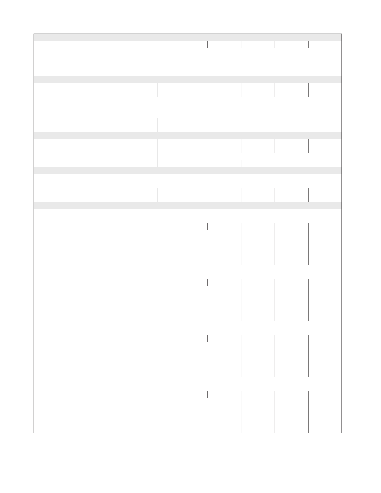
ENGINEERING DATA (MODELS 100-250)
Air System Data
Rated Flow Capacity at 100°F, 100 psig Inlet, 100°F Ambient Temperature 100 125 150 200 250
Maximum / Minimum Inlet Air Pressure (compressed air at inlet to dryer) 232 psig (16 barg) / 30 psig (2 barg)
Maximum / Minimum Inlet Air Temperature (compressed air at inlet to dryer) 120°F (49°C) / 40°F (4°C)
Maximum / Minimum Ambient Temperature 110°F (43°C) / 40°F (4°C)
Outlet Air Temperature (nominal at rated conditions) 85°F (29°C)
Refrigeration System Data
Refrigeration Capacity @ 35°F Evaporator & 100°F Ambient (BTU/hr) 60 Hz 4820 7130 8900 15200
50 Hz 4020 7340 7420 12700
Refrigerant Type R-134A
Refrigerant Charge See Data Tag on Dryer
Suction Pressure Setting - Hot Gas Bypass Valve (psig) 30.5 psig (2.1 barg
Compressor Control Ranges (out-in) High N/A 281 - 190 psig (19.4 - 13.1 barg)
Low N/A 22 - 34 psig (1.5 - 2.3 barg)
Air-Cooled Condensers
Air Flow Across Condenser (cfm) (air-cooled models) 60 Hz 300 450 710 1070
50 Hz 250 370 590 890
Condenser Fan Switch Setting (in-out) Fan 1 110 - 70 psig (7.6 - 4.8 barg) 113 - 78 psig (7.8 - 5.4 barg)
Fan 2 N/A
Water-Cooled Condensers
Water Regulating Valve Setting 135 psig (9.3 barg)
Required Available Water Pressure Differential 40 psig (2.8 barg) - minimum
Flow Required with 85°F Cooling Water (gallons per minute) 60 Hz N/A 1.1 2.0
50 Hz N/A 0.9 1.7
Electrical Data
Nominal Voltage 115/1/60 208-230/3/60
Min. - Max. Voltage 104 - 127 187 - 253
Input Power @ Rated Flow (watts) 932 1280 1298 1255 1962
Rated Load Amps** 10.2 13.0 7.5 10.4
Locked Rotor Amps** 51.0 70.0 51.0 66.0
Minimum Circuit Ampacity 13.6 18.0 10.5 15.9
Branch Circuit Fuse Size (amps) 20 25 15 20
Resistance (ohms) 4.3 S / 0.7 R 3.2 S / 0.4 R 1.8 1.3
Nominal Voltage 208-230/1/60 460/3/60
Min. - Max. Voltage 187 - 253 414 - 506
Input Power @ Rated Flow (watts) 932 1280 1298 1255 1962
Rated Load Amps** 5.4 6.5 3.6 4.7
Locked Rotor Amps** 30.0 35.0 25.0 33.0
Minimum Circuit Ampacity 7.3 9.1 5.2 7.5
Branch Circuit Fuse Size (amps) 15 15 15 15
Resistance (ohms) Main/Start 9.0 S / 2.3 R 7.9 S / 1.6 R 7.4 5.0
Nominal Voltage 100/1/50 575/3/60
Min. - Max. Voltage 90 - 110 518 - 633
Input Power @ Rated Flow (watts) 680 1019 991 1255 1962
Rated Load Amps 10.2 13.0 3.6 4.7
Locked Rotor Amps 51.0 70.0 25.0 33.0
Minimum Circuit Ampacity 13.6 18.0 4.2 6.0
Branch Circuit Fuse Size (amps) 20 25 15 15
Resistance (ohms) 4.3 S / 0.7 R 3.2 S / 0.4 R 7.4 5.0
Nominal Voltage 240/1/50 380-420/3/50
Min. - Max. Voltage 216 - 264 342 - 462
Input Power @ Rated Flow (watts) 680 1019 991 1002 1613
Rated Load Amps** 4.5 5.0 3.6 4.7
Locked Rotor Amps** 21.0 30.0 25.0 33.0
Minimum Circuit Ampacity 6.2 7.3 5.2 7.5
Branch Circuit Fuse Size (amps) 15 15 15 15
Resistance (ohms) 19.5 S / 3.3 R 10.5 S / 1.8 R 7.4 5.0
* For 60 Hz, 35°F Evaporator, 100°F Ambient; for 50Hz, 35°F Evaporator, 77°F Ambient
** Compressor Only
11
ENGINEERING DATA (MODELS 300-750)
Air System Data
Rated Flow Capacity at 100°F, 100 psig Inlet, 100°F Ambient Temperature 300 400 500 600 750
Maximum / Minimum Inlet Air Pressure (compressed air at inlet to dryer) 232 psig (16 barg) / 30 psig (2 barg)
Maximum / Minimum Inlet Air Temperature (compressed air at inlet to dryer) 120°F (49°C) / 40°F (4°C)
Maximum / Minimum Ambient Temperature 110°F (43°C) / 40°F (4°C)
Outlet Air Temperature (nominal at rated conditions) 85°F (29°C)
Refrigeration System Data
Refrigeration Capacity @ 35°F Evaporator & 100°F Ambient (BTU/hr) 60 Hz 15200 19200 22000 30500
50 Hz 12700 16000 18300 25400
Refrigerant Type R-134A
Refrigerant Charge See Data Tag on Dryer
Suction Pressure Setting - Hot Gas Bypass Valve (psig) 30.5 psig (2.1 barg
Compressor Control Ranges (out-in) High 281 - 190 psig (19.4 - 13.1 barg)
Low 22 - 34 psig (1.5 - 2.3 barg)
Air-Cooled Condensers
Air Flow Across Condenser (cfm) (air-cooled models) 60 Hz 1070 2470 1680 2170
50 Hz 890 2060 1400 1810
Condenser Fan Switch Setting (in-out) Fan 1 113 - 78 psig (7.8 - 5.4 barg)
Fan 2 N/A 183 - 124 psig (12.6 - 8.6 barg)
Water-Cooled Condensers
Water Regulating Valve Setting 135 psig (9.3 barg)
Required Available Water Pressure Differential 40 psig (2.8 barg) - minimum
Flow Required with 85°F Cooling Water (gallons per minute) 60 Hz 2.0 2.1 4.9 6.8
50 Hz 1.7 1.8 4.1 5.6
Electrical Data
Nominal Voltage 208-230/3/60
Min. - Max. Voltage 187 - 253
Input Power @ Rated Flow (watts) 1999 2031 2680 2910 4120
Rated Load Amps** 10.4 11.4 13.9 22.1
Locked Rotor Amps** 66.0 75.0 88.0 115.0
Minimum Circuit Ampacity 15.9 20.0 19.7 30.4
Branch Circuit Fuse Size (amps) 20 25 30 45
Resistance (ohms) 1.3 1.1 1.0 0.7
Nominal Voltage 460/3/60
Min. - Max. Voltage 414 - 506
Input Power @ Rated Flow (watts) 1999 2031 2680 2910 4120
Rated Load Amps** 4.7 5.1 7.1 9.6
Locked Rotor Amps** 33.0 40.0 44.0 63.0
Minimum Circuit Ampacity 7.5 9.6 10.4 15.2
Branch Circuit Fuse Size (amps) 15 15 15 20
Resistance (ohms) Main/Start 5.0 4.1 4.0 2.7
Nominal Voltage 575/3/60
Min. - Max. Voltage 518 - 633
Input Power @ Rated Flow (watts) 1999 2031 2680 2910 4120
Rated Load Amps 4.7 5.1 7.1 9.6
Locked Rotor Amps 33.0 40.0 44.0 63.0
Minimum Circuit Ampacity 7.5 7.7 8.3 12.2
Branch Circuit Fuse Size (amps) 15 15 15 20
Resistance (ohms) 5.0 4.1 4.0 2.7
Nominal Voltage 380-420/3/50
Min. - Max. Voltage 342 - 462
Input Power @ Rated Flow (watts) 1622 1667 1992 2040 2860
Rated Load Amps** 4.7 5.1 7.1 9.6
Locked Rotor Amps** 33.0 40.0 44.0 63.0
Minimum Circuit Ampacity 7.5 8.1 10.4 15.2
Branch Circuit Fuse Size (amps) 15 15 15 20
Resistance (ohms) 5.0 4.1 4.0 2.7
* For 60 Hz, 35°F Evaporator, 100°F Ambient; for 50Hz, 35°F Evaporator, 77°F Ambient
** Compressor Only

12
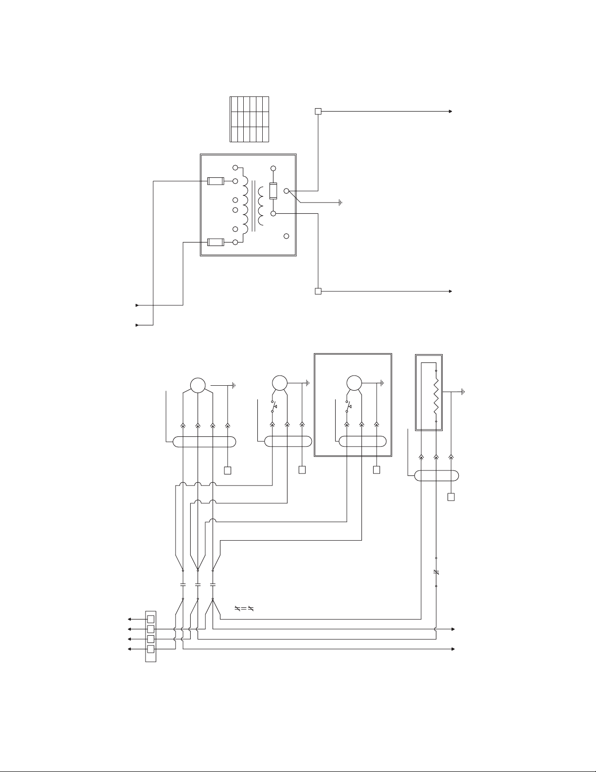
COMPRESSOR HARNESS
PE
T2
T1
FAN 1 HARNESS
IO
PE
GROUND
STUD
L2
L1
L2
230 VAC
CUSTOMER SUPPLIED
L1 PE
PILOT LIGHT
POWER ON
T2
T2
T2
T1
T1
A
PE
T2
T1 T1
FPS 1
FAN 1
MTR2
START RELAY
SR
SR
L3
L3
M6
5
S
CAPACITOR
4
OVERLOAD
31 3
MTR1
COMPRESSOR
R
C
S
POWER CORD SUPPLIED
120 VAC
WIRING DIAGRAM
Model 100: 120/230 VAC

13
WIRING DIAGRAM
Models 125-150: 120/230 VAC
RC - RUN CAPACITOR
SC - START CAPACITOR
SR - START RELAY
COMPRESSOR CONTACTOR
POWER ON
PILOT LIGHT
CONT 1
PE
PE
L1
CONT 1
6
L2
GROUND STUD
L2
L1
PE
230 VAC
CUSTOMER SUPPLIED
L1 L2
L2
L2
L1
L2
L1
L1
T2
T2
T1
T1
CONT 1
L1
N
4
5 5
A
PE
6
FAN 1 HARNESS
HEATER HARNESS
PE
L2
T2
T1 FPS 1
H1 H2
HEATER 1
MTR2 FAN 1
COMPRESSOR HARNESS
PE
1
C
4
COMPRESSOR
MTR1
120 VAC
POWER CORD SUPPLIED
-2NC
-1NC
L3
L2
L1
T3
T2
T1
O I
A1
SR
A2
C
R
S
RC
SC
1 2 5
14
COMPRESSOR
Optional Fan
(for 500-600 models only)
TO LINE 22
21
20
18
19
17
16
15
14
13
L1 L3
L2 CONT 1
-1NC
PE
HEATER HARNESS
-2NC 1L2
L3
TB2
TB2
PE
T3
T2
H1 H2
HEATER 1
FAN 2 HARNESS
FPS 2
MTR3 FAN 2
REF SHEET 02 LINE 11
REF SHEET 02 LINE 10
REF SHEET 01 LINE 20
03
10
11
12
09
08
07
06
05
04
L3
L3
L3
L2
L2
L3
L2
T3
T2
02
01
00
PETB1 L1 L2 L3
L1
L1
460 VAC
3 PHASE 60 Hz
L1 L2 L3
L1
CONT 1
T1
PE
TB2
T1
T2
T3
T3
T2
T3
TB2
PE
T2
T3
T2
FAN 1 HARNESS
FPS 1
MTR2 FAN 1
MTR1
T1
T1
T1
COMPRESSOR HARNESS
TO SHEET 02
43
42
X
40
41
39
38
37
36
35
TO SHEET 02
N
XF
25
(4 Terminal Blocks)
TB2
32
33
34 X
31
30
X
29
28
27
26
X1
FU3
X3
X2
FU2
H6 H5
FU1
H4 H3 H2 H1
FROM LINE 21
L3
24
23 L1
22 L3
L1
L3
L1
(4 Terminal Blocks)
FACTORY SET TO 460V
N
460V
575V
400V
H6
H6
H6
TB2
N
H2
H1
H3
L2
230V
208V
H6
H6
L1
H4
H5
WIRING DIAGRAM
Models 200-600, (460 VAC)
Sheet 1 of 2
15
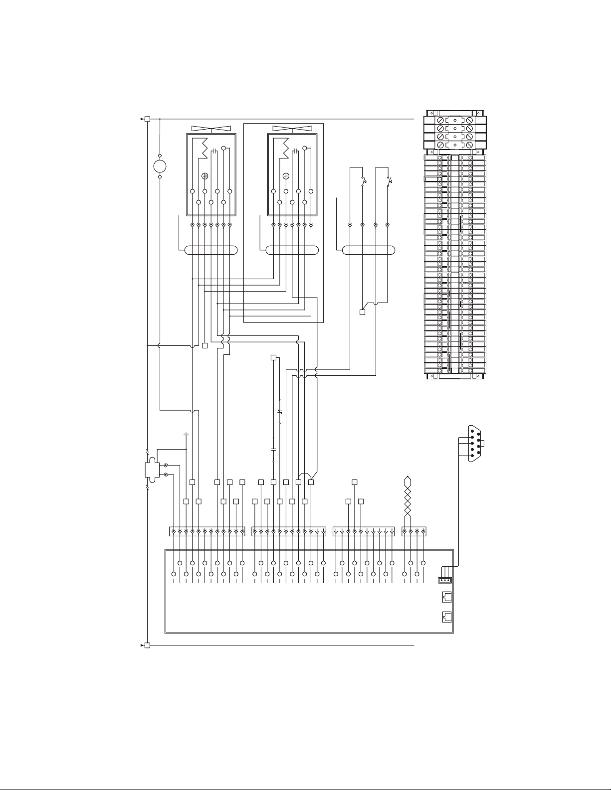
Drain Alarm #2 Input
13 21
W36
W28
W37
W34
W32
W30
FMD #1 In (RJ-11)
FMD #2 In (RJ-11)
J2 RS-232
RED
BLACK
WHITE
22
21
20
19
18
17
16
15
14
W38
Evaporator Thermistor
Evaporator Thermistor
Phase B xfmr Input
Phase A xfmr Input
Phase Com. xfmr Input
W4
N/A
N/A W7
W6
W5
N/A
W35
Gnd. (W28 thru W32)
Remote/Local Input
Remot Start/Stop Input
N/A
N/A
W33
W31
N/A
N/A
N/A
W29
W12
30
37
35
36
34
35
34
33
32
31
TCI
TB2
TB2
25
29
28
27
26
28
27
26
24
23
22
23
22
TB2
28
26
27
EMM INSTRUMENT BOARD
W20
W24
W26
W22
12
11
10
09
07
08
06
05
04
Gnd (W8 thru W14)
Drain Alarm #1 Input
Low Pressure Sw. Input
Heater #1 ON Input
High Pressure Sw. Input
Alarm A Com.
Compressor #1 ON Input
Alarm A N/C
Alarm A N/O
W15
W13
W14
W11
W10
W9
W8
W21
W19
Alarm B N/C
Alarm B Com.
Drain Test Output
Alarm B N/O
Drain Test Output
Compressor #1 Output
Compressor #1 Output
W27
W18
W17
W16
N/A
N/A W25
W23
FROM SHEET 01
01
03
02
00
Chassis Gnd.
TB2
X
24VAC IN
24VAC IN W3
W2
W1
X
TB2
3X
REMOVE JUMPER IF OPTIONAL DRAIN INSTALLED
-4NO
TB2
TB2
TB2
TB2
TB2
19
20
21
18
17
19
20
21
18
17
14
16
15
13
12
14
16
15
13
12
16 TB2
TB2
TB2
20
18
19
17
TB2
TB2
14
12
15 15
13
TB2
TB2
TB2
10
11
9
8
10
11
9
8
7
6
4
5
7
4
TB2
TB2
10
8
11
9
TB2
4
7
X
-3NO
CONT 1 19
16 -1NC
20
19
18
17
CONT 1 -2NC 19
4
8
7
BLU
TB2
CONNECTOR
PE
2
1
PE
2
1
PE
BRN
RED BRN
F1
LOAD
LINE WHITE
PE
BLU
TERMINAL BLOCK LAYOUT
TB2
19
18
19
TB2
HPS/LPS SENSOR HARNESS
17
19
HPS
TB1
LPS
HPS
L1 L1
8
X
X
4
N
X
X
N
N
N
4
4
4
8
7
7
19
15
11
10
9
14
13
12
18
17
16
19
19
19
26
21
20
28
27
PE
PE
PE
PE
L3
L2
PE
L3
L2
PE
4
6
3
1
1
3
6
4
TB2
19
TB2 PE
OPTIONAL DRAIN
DRAIN 2 HARNESS
X
N
20
19
7
8
5
3
2
8
7
19
20
N
X
5
3
2
DRAIN 1 HARNESS
4
24VAC
ALM
TEST
TEST
ALM
24VAC
CONTACTOR
COMPRESSOR
CONT 1
A1 A2 N
FROM SHEET 01
TB2 N
BLACK
WHITE
(Mounted in Enclosure)
DB9 MALE CONNECTOR
3
89
5
RED
4
67
21
WIRING DIAGRAM
Models 200-600, (460 VAC)
Sheet 2 of 2

16
COMPRESSOR
TO LINE 22
21
20
18
19
17
16
15
14
13
L1 L3
L2
CONT 1
-1NC
PE
HEATER HARNESS
-2NC 1L2
L3
TB2
TB2
PE
T3
T2
H1 H2
HEATER 1
FAN 2 HARNESS
FPS 2
MTR3 FAN 2
REF SHEET 02 LINE 11
REF SHEET 02 LINE 10
REF SHEET 01 LINE 20
03
10
11
12
09
08
07
06
05
04
L3
L3
L3
L2
L2
L3
L2
T3
T2
02
01
00
PE
L1
L1
L1
L2
L3
460 VAC
3 PHASE 60 Hz
TB1 L1 L3L2
L1
CONT 1
T1
DISCONNECT SWITCH
PE
TB2
T1
T2
T3
T3
T2
T3
TB2
PE
T2
T3
T2
FAN 1 HARNESS
FPS 1
MTR2 FAN 1
MTR1
T1
T1
T1
COMPRESSOR HARNESS
TO SHEET 02
43
42
X
40
41
39
38
37
36
35
TO SHEET 02
N
XF
25
(4 Terminal Blocks)
TB2
32
33
34 X
31
30
X
29
28
27
26
X1
FU3
X3
X2
FU2
H6 H5
FU1
H4 H3 H2 H1
FROM LINE 21
L3
24
23 L1
22 L3
L1
L3
L1
(4 Terminal Blocks)
FACTORY SET TO 460V
N
460V
575V
400V
H6
H6
H6
TB2
N
H2
H1
H3
L2
230V
208V
H6
H6
L1
H4
H5
WIRING DIAGRAM
Model 750, (460 VAC)
Sheet 1 of 2

17
Drain Alarm #2 Input
13
21
W36
W28
W37
W34
W32
W30
FMD #1 In (RJ-11)
FMD #2 In (RJ-11)
J2 RS-232
RED
BLACK
WHITE
22
21
20
19
18
17
16
15
14
W38
Evaporator Thermistor
Evaporator Thermistor
Phase B xfmr Input
Phase A xfmr Input
Phase Com. xfmr Input
W4
N/A
N/A W7
W6
W5
N/A
W35
Gnd. (W28 thru W32)
Remote/Local Input
Remot Start/Stop Input
N/A
N/A
W33
W31
N/A
N/A
N/A
W29
W12
30
37
35
36
34
35
34
33
32
31
TCI
TB2
TB2
25
29
28
27
26
28
27
26
24
23
22
23
22
TB2
28
26
27
EMM INSTRUMENT BOARD
W20
W24
W26
W22
12
11
10
09
07
08
06
05
04
Gnd (W8 thru W14)
Drain Alarm #1 Input
Low Pressure Sw. Input
Heater #1 ON Input
High Pressure Sw. Input
Alarm A Com.
Compressor #1 ON Input
Alarm A N/C
Alarm A N/O
W15
W13
W14
W11
W10
W9
W8
W21
W19
Alarm B N/C
Alarm B Com.
Drain Test Output
Alarm B N/O
Drain Test Output
Compressor #1 Output
Compressor #1 Output
W27
W18
W17
W16
N/A
N/A W25
W23
FROM SHEET 01
01
03
02
00
Chassis Gnd.
TB2
X
24VAC IN
24VAC IN W3
W2
W1
X
TB2
3X
REMOVE JUMPER IF OPTIONAL DRAIN INSTALLED
-4NO
TB2
TB2
TB2
TB2
TB2
19
20
21
18
17
19
20
21
18
17
14
16
15
13
12
14
16
15
13
12
16 TB2
TB2
TB2
20
18
19
17
TB2
TB2
14
12
15 15
13
TB2
TB2
TB2
10
11
9
8
10
11
9
8
7
6
4
5
7
4
TB2
TB2
10
8
11
9
TB2
4
7
X
-3NO
CONT 1 19
16 -1NC
20
19
18
17
CONT 1 -2NC 19
4
8
7
BLU
TB2
CONNECTOR
PE
2
1
PE
2
1
PE
BRN
RED BRN
F1
LOAD
LINE WHITE
PE
BLU
TERMINAL BLOCK LAYOUT
TB2
19
18
19
TB2
HPS/LPS SENSOR HARNESS
17
19
HPS
TB1
LPS
HPS
L1 L1
8
X
X
4
N
X
X
N
N
N
4
4
4
8
7
7
19
15
11
10
9
14
13
12
18
17
16
19
19
19
26
21
20
28
27
PE
PE
PE
PE
L3
L2
PE
L3
L2
PE
4
6
3
1
1
3
6
4
TB2
19
TB2 PE
OPTIONAL DRAIN
DRAIN 2 HARNESS
X
N
20
19
7
8
5
3
2
8
7
19
20
N
X
5
3
2
DRAIN 1 HARNESS
4
24VAC
ALM
TEST
TEST
ALM
24VAC
CONTACTOR
COMPRESSOR
CONT 1
A1 A2 N
FROM SHEET 01
TB2 N
BLACK
WHITE
(Mounted in Enclosure)
DB9 MALE CONNECTOR
3
89
5
RED
4
67
21
WIRING DIAGRAM
Model 750, (460 VAC)
Sheet 2 of 2

18
WIRING DIAGRAM
Models 200-750, 575-460/3/60 Transformer Pack

19
DIMENSIONS / WEIGHTS
NOTE: Dimensions and Weights are for reference only. Request certified drawings for construction purposes.
FRONT VIEW
BOTTOM VIEW
RIGHT SIDE VIEW
BACK VIEW
DETAIL A
A
“B”
“A”
“D”
“E” “F”
“G”
“H”
“I” “J”
“C”
Ø “K” MOUNTING HOLE
4-PLACES TYP.
“L” - I/O CONNECTIONS
2.500
CONDENSER AIR FLOW
6-FT (1.8 Meters) POWER CORD
MODELS 100-150 (115 VOLT)
ELECTRICAL ENTRY
MODELS 100-150 (230 VOLT)
0.25-NPT DRAIN CONNECTION
MODELS 100-150
ELECTRICAL ENTRY
MODELS 200-750
RS-232 ACCESS
MODELS 200-750
0.25-NPT DRAIN CONNECTION
MODELS 200 - 600
0.25-NPT DRAIN CONNECTION
MODEL 750 ONLY “N”
“M”
“O” 1/2-18 FPT I/O WATER CONNECTIONS
MODELS 200 - 750 ONLY
Dimensions, inches (mm)
Model 100 125 150 200 250 300 400 500 600 750
A 37.56 (954) 37.56 (954) 37.56 (954) 38.60 (980) 38.60 (980) 45.38 (1153) 45.38 (1153) 58.06 (1475) 58.06 (1475) 58.06 (1475)
B 25.62 (651) 25.62 (651) 25.62 (651) 32.15 (817) 32.15 (817) 32.15 (817) 32.15 (817) 32.15 (817) 32.15 (817) 32.15 (817)
C 1.63 (41) 1.63 (41) 1.63 (41) 1.88 (48) 1.88 (48) 2.63 (67) 2.63 (67) 2.77 (70) 2.77 (70) 2.77 (70)
D 23.62 (600) 23.62 (600) 23.62 (600) 30.15 (766) 30.15 (766) 30.15 (766) 30.15 (766) 30.15 (766) 30.15 (766) 30.15 (766)
E 17.62 (448) 17.62 (448) 17.62 (448) 30.15 (766) 30.15 (766) 30.15 (766) 30.15 (766) 39.62 (1006) 39.62 (1006) 39.62 (1006)
F 19.62 (498) 19.62 (498) 19.62 (498) 32.15 (817) 32.15 (817) 32.15 (817) 32.15 (817) 41.62 (1057) 41.62 (1057) 41.62 (1057)
G 9.58 (243) 9.58 (243) 9.58 (243) 7.64 (194) 7.64 (194) 13.51 (343) 16.25 (413) 20.44 (519) 20.44 (519) 20.44 (519)
H 14.96 (380) 14.96 (380) 14.96 (380) 15.80 (401) 15.80 (401) 21.82 (554) 25.68 (652) 27.79 (706) 27.79 (706) 27.79 (706)
I 28.54 (725) 28.54 (725) 28.54 (725) 30.19 (767) 30.19 (767) 29.98 (761) 36.89 (937) 49.06 (1246) 49.06 (1246) 49.06 (1246)
J 25.02 (636) 25.02 (636) 25.02 (636) 26.04 (661) 26.04 (661) 25.74 (654) 32.82 (833) 44.78 (1137) 44.78 (1137) 44.78 (1137)
K 0.31 (7.9) 0.31 (7.9) 0.31 (7.9) 0.31 (7.9) 0.31 (7.9) 0.31 (7.9) 0.31 (7.9) 0.63 (16) 0.63 (16) 0.63 (16)
L 1 MPT 1 MPT 1 MPT 1.5 MPT 1.5 MPT 1.5 MPT 2 MPT 2.5 MPT 2.5 MPT 2.5 MPT
M N/A N/A N/A 4.56 (116) 4.56 (116) 4.56 (116) 4.56 (116) 4.81 (122) 4.81 (122) 4.81 (122)
N N/A N/A N/A 9.84 (250) 9.84 (250) 9.84 (250) 9.84 (250) 20.82 (529) 20.82 (529) 20.82 (529)
O N/A N/A N/A 3.13 (80) 3.13 (80) 3.13 (80) 3.13 (80) 3.13 (80) 3.13 (80) 3.13 (80)
Weight
lbs (kg) 251 (114) 273 (124) 279 (127) 425 (193) 463 (210) 527 (239) 571 (259) 684 (310) 691 (313) 734 (333)

20
TROUBLESHOOTING GUIDE (MODELS 100-150)
SYMPTOM POSSIBLE CAUSE(S) CORRECTIVE ACTION
A) Water downstream of dryer 1. Residual free moisture remaining in
downstream pipelines
2. Air bypass system is open
3. Inlet and Outlet connections are reversed
4. Airlinesdownstreamofdryerareexposed
to temperatures below the dew point.
5. Excessivefreemoisture(bulkliquid)at
dryer inlet.
6. Condensate not being drained
Drain mechanism is clogged or
inoperative.
Drainlineisrestrictedorfrozen.
Electric drains-timer not set to allow for
sufficient condensate removal.
7. Dryer overloaded resulting in elevated
dew point.
8. Refrigeration system not functioning
Blow out system with dry air
Check valve positions
Check for correct connection
Insulateorheattraceairlinesexposedtolow
ambients or dry air to lower dew point
Install separator ahead of dryer
Replace drain mechanism if inoperative.
Open drain line.
Electric drains-reset time so that all liquid is
discharged
Check inlet air temperature and pressure,
flow rate (compressor capacity) and ambient
air or water temperature.
See D below
B) High pressure drop across dryer 1. Excessiveairow
2. Freezingofmoistureinevaporator
because of refrigeration system fault
3. Separator filter element clogged
Check flow rate
See D below
Replace filter element
C) Dew point indicator in red area 1. Dryer overloaded resulting in high air
outlet temperature
2. Refrigeration system not functioning
properly resulting in high air outlet
temperature
See A 7
See D below
D) Refrigeration system not
functioning properly
1. Power on light off
2. Refrigeration compressor cycles
on and off
a. Power failure
b. Line disconnect switch open
c. Blown fuses, open breaker
d. Faulty wiring, loose terminals
a. High or low ambient conditions
b. Air-cooled - Dirty, clogged condenser fins,
obstructed flow across condenser, faulty
fan motor or fan control switch.
Check for power to unit
Close disconnect switch
Check for continuity
Have electrician check electrical connections.
Checkmin./max.temperatureranges
Clean condenser and check for free air
flow, if problem persists contact qualified
refrigeration repairman or manufacturer’s
service department.
This manual suits for next models
10
Table of contents
Other SPX Dehumidifier manuals

SPX
SPX HPD Series User manual

SPX
SPX Hankison HPRplus Series User manual

SPX
SPX Pneumatic Products IBP500 User manual

SPX
SPX HCD Series User manual

SPX
SPX RDH-HP Series User manual

SPX
SPX HANKISON HES Series User manual

SPX
SPX Hankison GCU Series User manual

SPX
SPX HANKISON HIT Series User manual

SPX
SPX DELAIR QD 90 User manual
Popular Dehumidifier manuals by other brands


ecozone
ecozone Dehumidier user manual

International Refrigeration Products
International Refrigeration Products DH470 user manual

Kenmore
Kenmore 25851 owner's manual

GEAppliances
GEAppliances ADEL30 owner's manual

Timco Tools
Timco Tools 102611934 Operation manual

Ingersoll-Rand
Ingersoll-Rand TZ730 user manual