SPX HANKISON HES Series User manual

SERVICE DEPARTMENT: (724) 746-1100
5006820 Rev. A 5/10
INSTRUCTION MANUAL
HES Series
Models: HES90, HES120, HES140, HES190,
HES240, HES280, HES360, HES450,
HES540, HES675
REFRIGERATED
TYPE
COMPRESSED
AIR DRYERS
CONTENTS
GENERAL SAFETY INFORMATION .................................... 2
RECEIVING, MOVING, AND UNPACKING .......................... 2
1.0 INSTALLATION........................................................... 3
2.0 DRYER OPERATION .................................................. 5
3.0 MAINTENANCE ........................................................ 9
SIZING.............................................................................. 9
ENGINEERING DATA
MODELS 90-240 .......................................................... 10
MODELS 280-675 ........................................................ 11
WIRING DIAGRAMS - STANDARD CONTROLLER
MODELS 90-140: 115/1/60 ......................................... 12
MODELS 90-140: 230/1/60 ......................................... 13
MODELS 190-540 ........................................................ 14-15
MODEL 675 ................................................................. 16-17
WIRING DIAGRAMS - ADVANCED CONTROLLER
MODELS 190-540 ........................................................ 18-19
MODEL 675 ................................................................. 20-21
WIRING DIAGRAM: 575-460/3/60 TRANSFORMER PACK
MODELS 190-675 ........................................................ 22
DIMENSIONS / WEIGHTS.................................................. 23
TROUBLESHOOTING GUIDE
STANDARD CONTROLLER: MODELS 90-675................. 24
ADVANCED CONTROLLER: MODELS 190-675 .............. 25
PARTS LIST....................................................................... 26
WARRANTY ..................................................................... 28

2
GENERAL SAFETY INFORMATION
1. PRESSURIZED DEVICES:
This equipment is a pressure
containing device.
• Donotexceedmaximumoperating
pressure as shown on equipment
serial number tag.
• Makesureequipmentisdepressurizedbefore
workingonordisassemblingitforservice.
2. ELECTRICAL:
This equipment requires electricity to
operate.
• Installequipmentincompliancewith
all applicable electrical codes.
• Standardequipmentissuppliedwithelectrical
enclosuresnotintendedforinstallationinhazardous
environments.
• Disconnectpowersupplytoequipmentwhen
performinganyelectricalservice
work.
3. BREATHING AIR:
• Airtreatedbythisequipmentmay
notbesuitableforbreathingwithout
furtherpurication.
Refertoapplicablestandardsandspecicationsfor
therequirementsforbreathingqualityair.
RECEIVING, MOVING, AND UNPACKING
A. RECEIVING
Thisshipmenthasbeenthoroughlychecked,packed
andinspectedbeforeleavingourplant.Itwas
received in good condition by the carrier and was so
acknowledged.
CheckforVisibleLossorDamage.Ifthisshipment
showsevidenceoflossordamageattimeofdelivery
toyou,insistthatanotationofthislossordamagebe
made on the delivery receipt by the carrier’s agent.
B. UNPACKING
Checkforconcealedlossordamage.Whena
shipment has been delivered to you in apparent
goodorder,butconcealeddamageisfoundupon
unpacking,notifythecarrierimmediatelyandinsist
on his agent inspecting the shipment. Concealed
damage claims are not our responsibility as our terms
areF.O.B.pointofshipment.
C. MOVING
In moving or transporting dryer, do not tip dryer onto
its side.
D. STORAGE/SHUT DOWN
Dryer should not be stored outside (either
packedorunpacked)orexposedtotheweather.Damage
to electrical and control components may result.
IMPORTANT: WATER-COOLEDUNITS-Ifunitisshutdown
inbelow-freezingtemperatures,thewater-cooled
condensermayfreezeandcausepermanentdamage.
Condenser must be drained when the unit is shut down.
IMPORTANT: Do not store dryer in temperatures above
130°F(54.4°C)orbelow20°F(-7°C).

3
IMPORTANT: READ PRIOR TO STARTING THIS EQUIPMENT
1.0 INSTALLATION
1.1 Location
A. For typical placement in a compressed air system, see
drawing.
B. Aircompressorintake–Locateaircompressorsothat
contaminantspotentiallyharmfultothedryer(e.g.
ammonia)arenotdrawnintotheairsystem.
C. Clearances Free air flow
Front36inches(914mm)
Back6inches(152mm)
Sides36inches(914mm)
Service-Tofacilitatemaintenanceleave36inches
(914mm)ofclearanceinfrontofdryer.
D. Standard units are designed to operate in ambients:
Air-cooled:40to110°F(4to43°C).
Water-cooled:40to130°F(4to54°C).
E. Theinstallationofaexibleconnectionpriortothe
dryerisrecommendedtopreventpossibledamagefrom
vibration.
NOTE:Outdoorinstallation–Standardunitsaredesigned
forindoorinstallation.Contactmanufacturerifinstalling
outdoors.
Aftercooler
Separator
Dryer
Oil Removal
Filter
Compressor
Moisture Separator
Float Drain
(Standard)
Coalescing Filter
(Option)
Condenser
Drain Outlet
Electrical Entry
(230 VAC)
Air Outlet
Air Inlet
Control Panel
Models 90, 120, & 140
Electric Demand Drain (EDD)
3-Way Valve
Moisture Separator
Coalescing Filter
(Option)
Control Panel
RS232 Entry
Electrical Entry
Air Outlet
Air Inlet
Condenser
Drain Outlet
Models 190, 240, 280, 360, 450, 540, & 675
4
1.2 Mounting
Mountthedryeronalevelsolidsurface.Holesare
provided in the dryer base to permanently mount the
dryer to the floor.
1.3 Piping connections
A. AirInlet-Connectcompressedairlinefromairsourceto
airinlet.(Referencemarkingsondryerforairinlet/outlet
connectionlocations.)
RefertoSerialNumberTagformaximum
workingpressure.Donotexceeddryer’sMaximumWorking
Pressure.
NOTE: Install dryer in air system at highest pressure
possible(e.g.beforepressurereducingvalves).
NOTE: Install dryer at coolest compressed air temperature
possible.Maximuminletcompressedairtemperature:
130°F(54°C).Ifinletairexceedsthistemperature,precool
theairwithanaftercooler.
B. AirOutlet–Connectairoutlettodownstreamairlines.
C. Bypasspiping–Ifservicingthedryerwithoutinterrupting
the air supply is desired, piping should include inlet and
outlet valves and an air bypass valve.
D. Watercooledmodels–coolingwaterinletandoutlet
1. Connect cooling water supply to cooling water inlet.
2. Connect cooling water return line to cooling water
outlet connection.
NOTE: Strainer and water regulating valve are supplied on
water cooled models.
1.4 Electrical connections
IMPORTANT: Use copper supply wires only.
A. Dryer is designed to operate on the
voltage,phase,andfrequencylistedon
the serial number tag.
B. Ifdryerissuppliedwithacordandplug,installina
receptacleofpropervoltage.
C. Electrical entry on larger dryers is through a hole in the
cabinet.Itislocatedontherightsidepanelwhenfacing
thefrontoftheunit.Connectpowersourcetoterminal
strip in electrical enclosure as shown on the wiring
diagram included with the dryer.
NOTE: The dryer should NOTbewiredtocycleon/offwith
the air compressor.
1.5 Moisture separator
A. Models 90-140:
Separator (and Oil Removal Filter where
applicable)hasaninternaldrainwhich
automatically discharges condensate.
Models 190-675:
Separator(andOilRemovalFilterwhereapplicable)has
anelectronicdemanddrain(EDD)whichautomatically
discharges condensate.
NOTE:Itmaybedesirabletopipethecondensatefrom
the Automatic Drain outlet to a suitable drain.
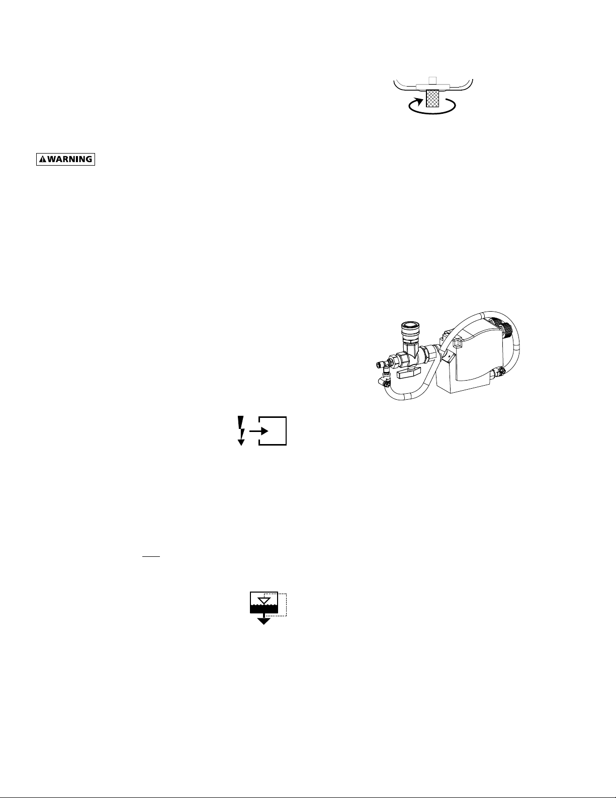
B. Models 90-140:
Separatorhasaknurledttingwithexibledrain
tubingattached.Besureknurledttingistightened
byturningcounter-clockwisebeforeoperatingdryer.
TO CLOSE
TURN COUNTERCLOCKWISE
C. Models 190-675
For manual draining, convenient dryer
depressurization,andEDDservice,athree-wayvalve
assemblyhasbeeninstalledatthebottomofthe
moistureseparator(andcoldcoalescinglterwhere
applicable).Reviewthefollowingforproperdrain
function:
• AutomaticDraining-Valvehandleshouldbe
positionedparalleltothevalvebody(asshown),with
the arrow on the handle pointing toward the EDD.
Inthisposition,condensatewillowfromthebowl
to the EDD.
• DrainIsolation(Shutdown)-Valvehandleshallbe
turnedperpendiculartothevalvebody(rotate90°).
Inthisposition,condensateowisshutoff.
• ManualDraining-Drainvalvehandleshallberotated
slightly past the drain isolation position to allow
throttlingthroughthevalveformanualdischarge
anddepressurization.
• Note:Thequickdisconnectttingallowsremoval
oftheentiredrainassembly.However, the unit
must be depressurized prior to disassembly or
serious injury may occur.
NOTE: Discharge is at system pressure. Drain line should
be anchored.
NOTE: Condensate may contain oil. Comply with
applicable laws concerning proper disposal.
1.6 EDD Operation
A. Verifythatisolationvalvesareopen.Ifthedrainfailsto
dischargeafterthevalveisenergized,theelectronic
controlcircuitwillrepeatedlyenergizethevalveinan
attempttoclearthedischargeport.If,after60seconds,
thedrainstillfailstodischarge,thecontrolcircuitthen
switches to the alarm mode. In this mode the valve is
de-energizedandtheredalarmlightisactivatedonthe
drain.Thevalveisthenautomaticallyenergizedevery4
minutesfor5seconds.Checkthedrainoperation.Push
drain(push-to-test)buttononthedrainortheElectronic
Controller(ifequipped)toenergizedrain.Aowof
condensate and/or air should be present at the drain
outlet.Thealarmmodeautomaticallyclearsafterthe
drain returns to normal operation.
5
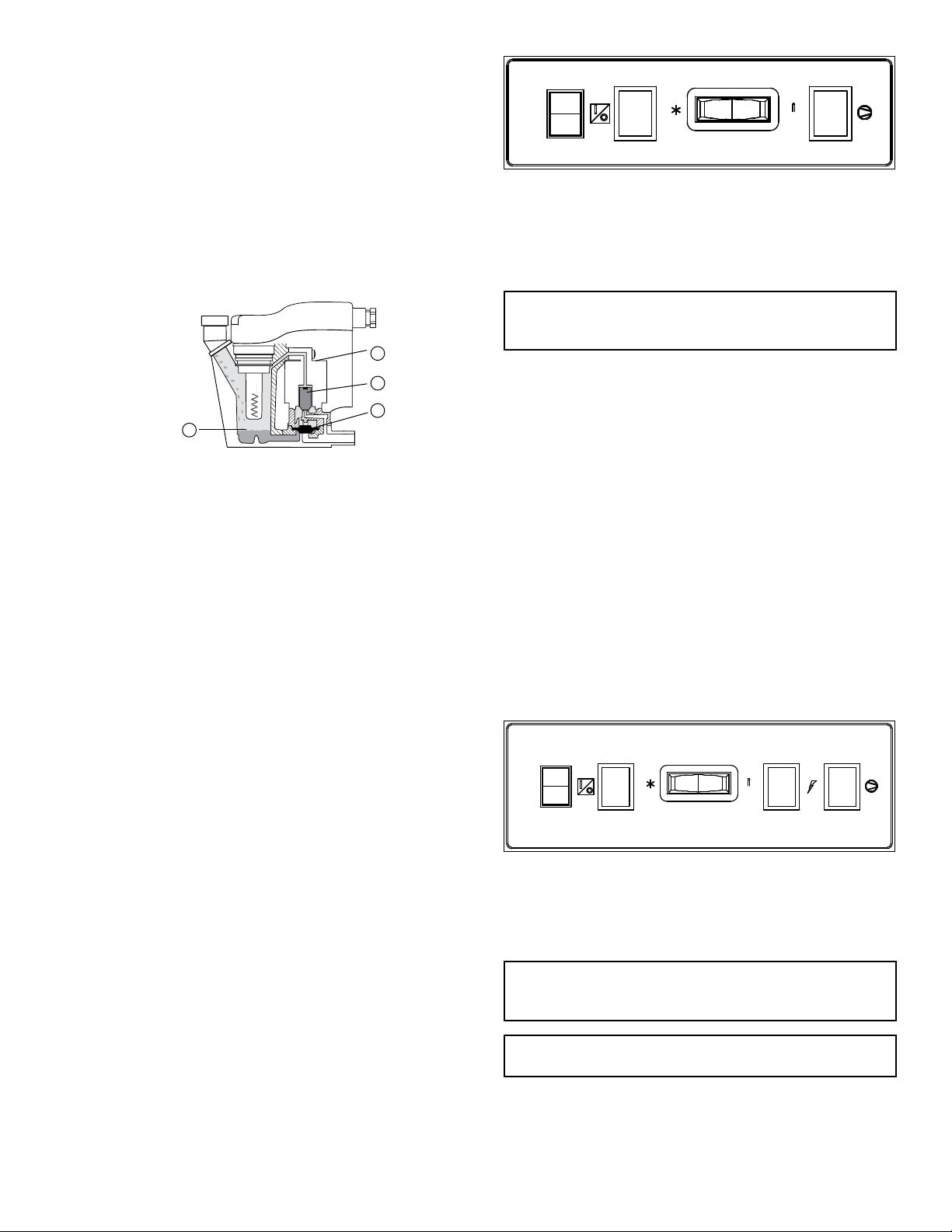
B. Condensate enters the reservoir (1) through the inlet
port. When the condensate level in the reservoir covers
the capacitance sensor, an electronic signal is sent to the
solid state countdown processor. The processor delays
theopeningofthesolenoidvalveforagivenperiod
oftime.Oncethetimehaselapsed,thesolidstate
processortransmitsinformationtoenergizethecoilin
the solenoid valve (2).Themagneticforceofthecoil
causes the solenoid core (3) to move, closing the pilot air
supplylineandopeningthepilotairexhaustline.After
the pilot air above the diaphragm (4) is vented, pressure
inthereservoiropensthedischargeportandforces
the condensate through the discharge port and outlet
piping.
2.0 DRYER OPERATION
BasicTheoryofOperation:Thisenergysavingsdryer
operatesusingaglycol/airheatexchangertoabsorb
heatfromtheairstream.Arefrigerationcompressoris
usedtocooltheglycolmixtureandwhenthedryerload
isreduced,theexcesscoolingfromthecompressoris
usedtolowerthetemperatureoftheglycol.Whenthe
glycol reaches a minimum temperature, the compressor is
turnedofftosaveenergy.Thedryercontinuestooperate
byusingtheglycolmixturetocooltheairstreamuntilthe
glycolreachesamaximumtemperaturesetpointatwhich
time the compressor again turns on to cool the glycol
mixture.
2.1 Minimum/Maximum operating conditions
A. Maximuminletairpressure:refertodryerserialnumber
tag
B. Minimuminletairpressure:30psig(2.1kgf/cm
2
)
C. Maximuminletairtemperature:130°F(54°C)
D. Maximumambienttemperature:
Air-cooledmodels:110°F(43°C)
Water-cooledmodels:130°F(54°C)
E. Minimumambienttemperature:40°F(4°C)
2.2 Start-up
A. Models 90-140: Standard Controller
Energizecompressorbypositioningtheon/offswitch
intheon(I)position.Poweronlightwillilluminate.
Compressor on light will illuminate. Compressor will
rununtilglycolmixtureiscooled.Therefrigerationunit
willthenturnoff,andthecompressoronlightwillbe
extinguished.
SLOWLYpressurizethedryerwithcompressedair.Fully
open the inlet and outlet valves. Dryer will operate
automatically and the compressor will cycle in response
to the air load.
On/Off DryerOn Dewpoint CompressorOn
Switch Light Indicator Light
B. Models 190-675: Standard Controller
Energizedryerbyapplyingpowertotheunit.Thegreen
dryerenergizedlightwillilluminate.
NOTICE: Energize dryer for 24 hours prior to starting
refrigerationcompressor!Failuretofollowthesenotices
mayresultinanon-warrantablecompressorfailure.
Energizecompressorbypositioningtheon/offswitch
intheon(I)position.Poweronlightwillilluminate.
Compressor on light will illuminate. Compressor will
rununtilglycolmixtureiscooled.Therefrigerationunit
willthenturnoff,andthecompressoronlightwillbe
extinguished.
NOTE:Checkforcorrectphasingofunit.
Onair-cooledmodels:checkfanrotation(airmustbe
pulledthroughthecondenser).Fansmaynotstart
immediatelyormaycycleonandoff.Ifrotationisinthe
wrongdirectionfollowtheprocedurebelow.
Onwater-cooledmodels:Afterstartingdryerifan
unusual noise is heard and the discharge line does not
get hot, stop the dryer, reverse two power leads, restart,
andverifydischargelinegetshot.
SLOWLYpressurizethedryerwithcompressedair.Fully
open the inlet and outlet valves. Dryer will operate
automatically and the compressor will cycle in response
to the air load.
On/Off Power-On Dewpoint Dryer Compressor
Switch Light Indicator Energized On
Light Light
C. Models190-675:AdvancedController(EMM)
Energizedryer.Greenpoweronlightwillilluminate.
NOTICE: Energize dryer for 24 hours prior to starting
refrigerationcompressor!Failuretofollowthesenotices
mayresultinanon-warrantablecompressorfailure.
NOTICE:Donotusedisconnectswitchtoremovepowerfrom
dryerforextendedperiodsexceptfordryerrepair.
1
2
3
4
6
D. AdvancedController(EMM)Setup
Press and hold Program Mode button until Main Menu
appears. Use the Up and Down arrow buttons to scroll
through the menu choices. Press Enter button in order
todisplaytheselectedmenuitem.PressESCtoexitthe
Main Menu and return to Display mode.
1. Language selection
a. Use the ‘Up’ and ‘Down’ arrow buttons to scroll
through available languages.
b. Press ‘Enter’ button to apply the current language
selection.
c. Push ‘ESC’ button to return to the Main Menu.
2. Setting Date & Time
a. Use the ‘Up’ and ‘Down’ arrow buttons to change
theselectedeld.Press‘Enter’buttontoaccept
newvalueandmovetothenexteld.
b. Push ‘ESC’ to return to the Main Menu.
NOTE: The selected value is indicated by a ‘_’.
3. Setting Schedule
a. Use the ‘Up’ and ‘Down’ arrow buttons to select the
dayofweekandoperation.Press‘Enter’toaccept
newvalueandmovetothenexteld.
b. Use the ‘Up’ and ‘Down’ arrow buttons to select
hours. Press ‘Enter’ to accept the hours and move
tothenexteld.
NOTE:‘IGNORE’allowsyoutoskipperformingthe
speciedaction.
c. Use the Up and Down arrow buttons to select
minutes. Press ‘Enter’ to accept the minutes and
returnto“Dayofweek/operation”selection.
d. Push ‘ESC’ when the schedule setup is complete to
return to the Main Menu.
4. Alarm History
a. Use the ‘Up’ and ‘Down’ arrow buttons to
scroll through the last 10 dryer alarms sorted in
chronological order.
b. Press ‘ESC’ to return to the Main Menu.
NOTE: Hold the alarm reset button to clear the alarm
history..
5. Energy Cost
a. Use the ‘Up’ and ‘Down’ arrow buttons to select the
desired currency. Press ‘Enter’ to accept the new
valueandmovetothenexteld.
b. Use the ‘Up’ and ‘Down’ arrow buttons to select the
energy cost. Press ‘Enter’ to accept the new value
andmovetothepreviouseld.
c. Press ‘ESC’ to return to the Main Menu.
6. Service Interval
a. Use the ‘Up’ and ‘Down’ arrow buttons to program
the desired service interval. Press ‘Enter’ to accept
the new service interval value.
b. Press ‘ESC’ to return to the Main Menu.
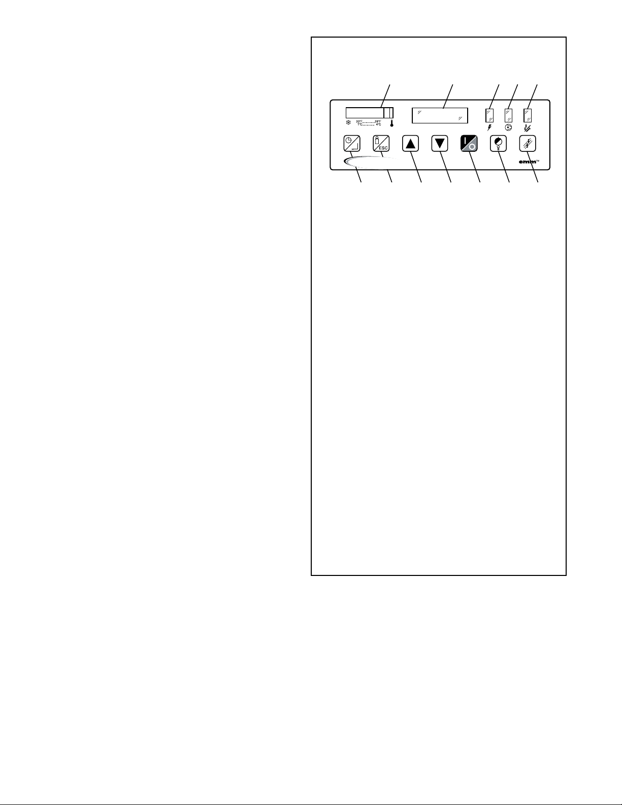
1. Glycol Temperature Indicator
2. TextDisplay
3. Power LED
4. Compressor LED
5. Alarm / Service LED
6. Schedule / Enter Button
a. In Display Mode: Toggle between manual and
scheduled dryer operating modes.
b. InSetupMode:Enterasub-menuorconrma
value.
7. Setup Mode / Escape Button
a. In Display Mode: Hold to enter setup mode.
b. InSetupMode:Presstoexitcurrentmenu.
8. Up Arrow
a. In Display Mode: Move to previous display
screen.
b. In Program Mode: Increment current menu/
value selection.
9. Down Arrow
a. InDisplayMode:Movetonextdisplayscreen
b. In Program Mode: Decrement current menu/
value selection.
10. On/OffButton:Presstotogglethedryeron/off
forcesdryertoentermanualmode.
11. Drain test: Press to momentarily open the
electronic demand drains.
12. Reset: Press to clear the current alarm message and
alarm/service LED.
CONTROL PANEL
1234 5
67891011 12
energy saving
AIR TREATMENT

7
7. Auto-Restart
a. Use the ‘Up’ and ‘Down’ arrow buttons to enable/
disable auto-restart. Press ‘Enter’ to accept the new
selection.
b. Press ‘ESC’ to return to the Main Menu.
E. Dryer Startup
NOTICE:EnergizeDryerfor24hourspriortostarting
refrigerationcompressor!Failuretofollowthesenoticesmay
resultinanon-warrantablecompressorfailure.
1. Start dryer 15 minutes prior to compressed air flow.
2. On water-cooled models: begin cooling water flow prior
to compressor startup.
3. Checkforproperelectricalvoltage.
4. Slowlypressurizeunitairsidebyopeninginletisolation
valve.Checkforleaks.
5. After15minutes,openoutletisolationvalveslowly.
6. Close air bypass valve.
7. Select dryer operating mode with Manual/Schedule
mode button.
NOTE:Checkforcorrectphasingofunit.
Onair-cooledmodels:checkfanrotation(airmustbepulled
throughthecondenser).Fansmaynotstartimmediatelyor
maycycleonandoff.Ifrotationisinthewrongdirection
followtheprocedurebelow.
Onwater-cooledmodels:Afterstartingdryerifanunusual
noise is heard and the discharge line does not get hot,
stopthedryer,reversetwopowerleads,restart,andverify
discharge line gets hot.
F. Dryer Operation
1. ManualMode-PushingtheOn/Offbuttonwillcausethe
dryertoturnonorturnoff.Dryerstatusisindicatedon
thetextdisplay.Thecompressorwillbegincyclingbased
on the glycol temperature. The compressor LED will
reectthestateofthecompressor.
2. Scheduled Mode - Pressing the Schedule Mode button
will cause the dryer to toggle between scheduled and
manual modes. In scheduled mode the dryer will turn
on/offbasedonthescheduleenteredduringthedryer
setup. The compressor will cycle based on the glycol
temperature when the dryer is on.
3. Remote Mode - By closing the remote mode contact the
dryerwillenteraremotecontrolmode.Thestateofthe
dryerwillbebasedontheremotecontrolcontact.Ifthe
contactisclosedthedryerwillrun,ifthecontactisopen
thedryerwillremainoff.
NOTE: The dryer may be returned to manual mode at any
time by pressing the schedule button. Manual Mode will
appearontextdisplay.Tore-enablescheduledoperation,
press the schedule button again.
Auto-Restart
Disabled(FactoryDefault)-Followingapowerinterruption
the dryer will begin operation in manual mode with the dryer
off.
Enabled - Following a power interruption the dryer will return
to the previous operating mode and will turn the dryer on or
offbasedonthemode.
Manual Mode - Dryer will return to state it was in prior to
powerfailure.
ScheduledMode-Dryerwillbeonoroffbasedonthe
programmed schedule.
RemoteMode-Dryerwillbeonoroffbasedonremote
control contact.
G. Dryer Display
1. Operating Mode - Displays the current date/time and
operating mode.
2. DryingStatus-Displaysthestatusofthedryer(on/off)
3. HourstoService-Displaysthehoursremainingbefore
dryer service is required.
4. Total Hours - Displays the total hours the dryer has been
operating.
5. Daily Run Time - Displays the average dryer load over the
last 24 hours.
6. Average Run Time - Displays the average dryer load over
the last 30 days.
7. Energy Savings - Displays the estimated annual energy
savings based on the average dryer load over the last 30
days.
8. Glycol Temperature - Displays the glycol temperature
reading.
H. Dryer Alarms
SERVICE DRYER - Indicates that the service interval
forthedryerhasexpired.Performrequireddryer
maintenance and reset using the alarm reset button.
HIGH DISCHARGE PRESSURE - Indicates that the
refrigerationcompressorcontrolcircuithasopened
becauseofhighheadpressure.Thehighpressure
switchmustberesetmanually.Afterxingthefaultand
resetting the pressure switch the alarm can be cleared
using the alarm reset button.
COMPRESSOR–Indicatesthatthecompressorcontactor
hasnotengaged.Checkthecompressorcontactor.
Oncethefaulthasbeencorrectedthealarmcanbe
manually cleared using the alarm reset button.
TEMPERATURESENSORFAILURE–Indicatesaproblem
withthe10kOhmNTCThermistor.Checktomakesure
the thermistor is properly connected to the control
board and the resistance across the Thermistor is correct.
Oncethefaulthasbeencorrected,thealarmcanbe
manually cleared using the alarm reset button.
HIGH TEMPERATURE -
HIGHGLYCOLTEMPERATURE–
Indicates that the dryer is overloaded or there is a
problemwiththerefrigerationsystemleadingtopoor
dryerperformance.Oncethefaulthasbeencorrected
the alarm can be manually cleared using the alarm reset
button.
HEATER–Indicatesaproblemwiththecrankcaseheater.
Thecrankcaseheatershouldenergizeanytimethe
dryerisoff.Checktomakesurethecrankcaseheateris
energized.Oncethefaulthasbeencorrectedthealarm
can be manually cleared using the alarm reset button.
DRAIN–Indicatesaproblemwiththeelectronicdemand
drain.Refertotheelectronicdemanddrainmanualfor
furtherinformationonhowtocorrectthedrainfault.
Oncethefaulthasbeencorrectedthealarmcanbe
manually cleared using the alarm reset button.

8
I. Using the RS-232 port
TheRS-232portisusedtomonitordryeroperationfrom
ahostcomputer.A(1to1)DB-9cableisrequiredto
connect dryer and computer. For PC connections, data
is transmitted on pin 2, received on pin 3, ground is pin
5, pins 7 and 8 are jumpered at dryer.
Operationisatxedbaudrateof9,600;asynchronous
formatis8bit,noparity,1stopbit(“8,N,1”).Nocheck
sumorerrorcorrectionvaluesareprovided.Ifrequired,
requeststatusstringtwo(ormore)timesandcompare
foragreement.
RequestdatabysendingASCII?character(3FH).
Responsemaytakeuptotwosecondsascertain
processingfunctionsmayrequirecompletionbefore
serialportisacknowledged.
Dryerrespondswithlinefeed(0AH),carriagereturn(0DH),
andcharacterstring:(1),(2),(3),(4),(5),(6),(7),(8),(9)
(1) =STX(start-of-textcharacter,mayappearasasmi-
leyfaceorsomeothercharacter
(2) =108,ControlboardID
(3) =0or1,Compressorrunningstatus(0=off,1=on)
(4) =MorS,OperatingMode(M=MANUALOVERRIDE,S
=SCHEDULERUNNING)
(5) =xxxx,HOURSTOSERVICE
(6) =xxxxxx,TOTALHOURS
(7) =xx,AlarmorServiceCode(0=noalarm,30=LOW
PRESSUREALARM,31=HIGHPRESSUREALARM,
32=COMPRESSORALARM,36=HIGHEVAPTEMP
ALARM,37=HEATERALARM,38=DRAINALARM,
39=SERVICEDRYER,41=TEMPSENSORALARM)
(8) =xx.x,Evaporatortemperature(°F)
(9) =ETX,(end-of-textcharacter,mayappearasaheart
orsomeothercharacter)
9
SIZING
Determining dryer capacity at actual operating conditions
Todeterminethemaximuminletowcapacityofadryer
at various operating conditions, multiply the rated capacity
fromTable1bythemultipliersshowninTable2.
Example:Howmanyscfmcananair-cooledmodel360handle
whencompressedairtobedriedisat200psigand110°F;
ambient air temperature is 80°F?
Answer:360x0.95x1.12=383scfm.
TABLE 1
Ratedcapacity(scfm)andpressuredrop@100psiginlet
pressure, 100°F inlet temperature, and 100°F ambient
temperature
MODEL 90 120 140 190 240
Rated capacity
of air-cooled
models (scfm)
60 Hz
50 Hz
90
75
120
100
140
117
190
158
240
200
MODEL 280 360 450 540 675
Rated capacity
of air-cooled
models (scfm)
60 Hz
50 Hz
280
233
360
300
450
375
540
450
675
562
TABLE 2
Aircapacitycorrectionfactors(Multipliers)
INLET COMPRESSED AIR CONDITIONS
INLET
PRESSURES
INLET TEMPERATURES
80°F 90°F 100°F 110°F 120°F 130°F
psig bar 27°C 32°C 38°C 43°C 49°C 54°C
30
50
80
100
125
150
175
200
250
2.0
3.4
5.5
6.9
8.6
10.4
12.1
13.8
17.2
1.24
1.40
1.55
1.61
1.67
1.71
1.75
1.77
1.81
0.92
1.07
1.19
1.25
1.30
1.34
1.37
1.39
1.43
0.71
0.83
0.95
1.00
1.05
1.08
1.11
1.14
1.17
0.56
0.66
0.77
0.82
0.86
0.90
0.92
0.95
0.98
0.44
0.54
0.63
0.68
0.72
0.75
0.78
0.80
0.83
0.35
0.44
0.52
0.56
0.61
0.64
0.66
0.68
0.72
COOLING MEDIUM*
AMBIENT
TEMPERATURE
MULTIPLIER
°F °C
80
90
100
110
27
32
38
43
1.12
1.06
1.00
0.94
*Air-cooled models; water-cooled models use 1.15 multiplier if cooling
water is below 35°C, 95°F.
3.0 MAINTENANCE
3.1 Condenser coil – Clean off accumulated dust
and dirt monthly.
3.2 Moisture separator – Replace filter element
when pressure drop across dryer is excessive,
or annually, whichever occurs first.
3.3 Check separator daily to be sure automatic
drain is discharging.
3.4 Blow down separator weekly.
3.5 Rebuild drain mechanism annually.
Tofacilitateservice,maintenancekitsareavailable.
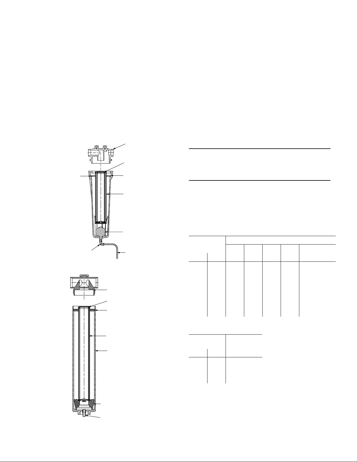
Models 90-140
Drain Line
PTC Swivel Elbow
Element
Wave Spring
Float Drain
Element O-Ring
Bowl O-Ring
Head
Models 190-675
Head
Element O-Ring
Bowl O-Ring
Element
Bowl
Drain Quick Disconnect
Bowl Support
*Models 500-750 Only.

10
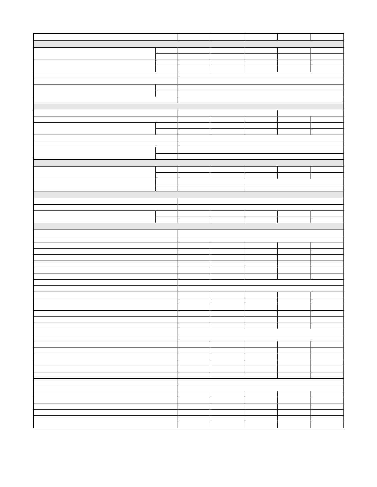
ENGINEERING DATA (MODELS 90-240)
Model 90 120 140 190 240
Air System Data
Rated Air Flow at 100°F & 100 psig Inlet, 100°F Ambient (scfm) 60 Hz, a-c 90 120 140 190 240
60 Hz, w-c n/a n/a n/a 219 276
Rated Air Flow at 95°F & 100 psig Inlet, 77°F Ambient (scfm) 50 Hz, a-c 95 127 148 201 254
50 Hz, w-c n/a n/a n/a 203 257
Minimum / Maximum Inlet Compressed Air Pressure 30 / 232 psig (2.1 / 16.0 barg)
Minimum / Maximum Inlet Compressed Air Temperature 40 / 120°F (4 / 49°C)
Minimum / Maximum Ambient Temperature a-c 40 / 110°F (4 / 43°C)
w-c 40 / 130°F (4 / 54°C)
Outlet Air Temperature (nominal at rated conditions) 85°F (29°C)
Refrigeration System Data
Compressor Type Hermetic, Reciprocating
Refrigeration Compressor Horsepower 0.5 0.75 0.75 1 1.5
Refrigeration Capacity @ Rated Flow (BTU/h) * 60 Hz, a-c 4,820 6,030 6,030 8,900 15,200
50 Hz, a-c 4,760 7,070 7,070 9,130 16,070
Refrigerant Type R-134A
Refrigerant Charge See Serial Tag on Dryer
Compressor Pressure Switch Setting (cut out / cut in) High, a-c N/A 281 - 190 psig (19.4 - 13.1 barg)
High, w-c N/A 200 - 160 psig (13.8 - 11.0 barg)
Air-Cooled Condenser
Air Flow Across Condenser (cfm) 60 Hz 300 450 450 710 1,070
50 Hz 250 370 370 590 890
Condenser Fan Pressure Switch Setting (cut in / cut out) Fan 1 110 / 70 psig (7.6 / 4.8 barg) 113 / 78 psig (7.8 / 5.4 barg)
Fan 2 N/A
Water-Cooled Condenser
Water Regulating Valve Setting 135 psig (9.3 barg)
Minimum Water Pressure Differential 40 psig (2.8 barg)
Cooling Water Flow with 85°F (gallons per minute) * 60 Hz N/A 1.3 1.5
50 Hz N/A 1.2 1.4
Electrical Data
Nominal Voltage 115/1/60 208-230/3/60
Voltage Range 104 - 127 187 - 253
Input Power @ Rated Flow (watts) * 978 1,282 1,293 1,363 1,942
Minimum Circuit Ampacity 13.6 18.3 18.3 10.5 15.9
Maximum Overcurrent Protector (amps) 20 25 25 15 20
Compressor Rated Load Amps 10.2 15.2 15.2 7.5 10.4
Compressor Locked Rotor Amps 51.0 66.3 66.3 51.0 66.0
Compressor Winding Resistance (ohms) 4.3 S / 0.7 R 3.2 S / 0.4 R 3.2 S / 0.4 R 1.8 1.3
Nominal Voltage 208-230/1/60 460/3/60
Voltage Range 187 - 253 414 - 506
Input Power @ Rated Flow (watts) * 978 1,282 1,293 1,363 1,942
Minimum Circuit Ampacity 7.3 10.5 10.5 5.2 7.5
Maximum Overcurrent Protector (amps) 15 15 15 15 15
Compressor Rated Load Amps 5.4 9.0 9.0 3.6 4.7
Compressor Locked Rotor Amps 30.0 33.5 33.5 25.0 33.0
Compressor Winding Resistance (ohms) 9.0 S / 2.3 R 7.9 S / 1.6 R 7.9 S / 1.6 R 7.4 5.0
Nominal Voltage 100/1/50 575/3/60 **
Voltage Range 90 - 110 518 - 633
Input Power @ Rated Flow (watts) * 1,363 1,942
Minimum Circuit Ampacity 13.6 18.3 18.3 4.2 6.0
Maximum Overcurrent Protector (amps) 20 25 25 15 15
Compressor Rated Load Amps 10.2 15.2 15.2 3.6 4.7
Compressor Locked Rotor Amps 51.0 66.3 66.3 25.0 33.0
Compressor Winding Resistance (ohms) 4.3 S / 0.7 R 3.2 S / 0.4 R 3.2 S / 0.4 R 7.4 5.0
Nominal Voltage 240/1/50 380-420/3/50
Voltage Range 216 - 264 342 - 462
Input Power @ Rated Flow (watts) *
Minimum Circuit Ampacity 6.2 9.9 9.9 5.2 7.5
Maximum Overcurrent Protector (amps) 15 15 15 15 15
Compressor Rated Load Amps 4.5 8.3 8.3 3.6 4.7
Compressor Locked Rotor Amps 21.0 53.0 53.0 25.0 33.0
Compressor Winding Resistance (ohms) 19.5 S / 3.3 R 10.5 S / 1.8 R 10.5 S / 1.8 R 7.4 5.0
NOTES:
* For 60 Hz: 35°F Evaporator & 100°F Ambient; for 50Hz: 35°F Evaporator & 77°F Ambient.
** 575/3/60 units use equipment transformers on incoming power. Compressor and fan voltage is 460/3/60.
11
ENGINEERING DATA (MODELS 280-675)
Model 280 360 450 540 675
Air System Data
Rated Air Flow at 100°F & 100 psig Inlet, 100°F Ambient (scfm) 60 Hz, a-c 280 360 450 540 675
60 Hz, w-c 322 414 518 621 776
Rated Air Flow at 95°F & 100 psig Inlet, 77°F Ambient (scfm) 50 Hz, a-c 297 382 477 572 716
50 Hz, w-c 300 385 482 578 722
Minimum / Maximum Inlet Compressed Air Pressure 30 / 232 psig (2.1 / 16.0 barg)
Minimum / Maximum Inlet Compressed Air Temperature 40 / 120°F (4 / 49°C)
Minimum / Maximum Ambient Temperature a-c 40 / 110°F (4 / 43°C)
w-c 40 / 130°F (4 / 54°C)
Outlet Air Temperature (nominal at rated conditions) 85°F (29°C)
Refrigeration System Data
Compressor Type Hermetic, Reciprocating Hermetic, Scroll
Refrigeration Compressor Horsepower 1.5 1.5 2 2.5 3.5
Refrigeration Capacity @ Rated Flow (BTU/h) * 60 Hz 15,200 15,200 19,200 22,000 30,500
50 Hz 16,070 16,070 20,060 21,120 29,650
Refrigerant Type R-134A
Refrigerant Charge See Serial Tag on Dryer
Compressor Pressure Switch Setting (cut out / cut in) High, a-c 281 / 190 psig (19.4 / 13.1 barg)
High, w-c 200 / 160 psig (13.8 / 11.0 barg)
Air-Cooled Condensers
Air Flow Across Condenser (cfm) 60 Hz 1,070 1,070 2,470 1,680 2,170
50 Hz 890 890 2,060 1,400 1,810
Condenser Fan Pressure Switch Setting (cut in / cut out) Fan 1 113 / 78 psig (7.8 / 5.4 barg)
Fan 2 N/A 183 / 124 psig (12.6 / 8.6 barg)
Water-Cooled Condensers
Water Regulating Valve Setting 135 psig (9.3 barg)
Minimum Water Pressure Differential 40 psig (2.8 barg)
Cooling Water Flow with 85°F (gallons per minute) * 60 Hz 1.7 2.1 2.5 3.0 3.6
50 Hz 1.6 2.0 2.3 2.8 3.3
Electrical Data
Nominal Voltage 208-230/3/60
Voltage Range 187 - 253
Input Power @ Rated Flow (watts) * 1,950 2,065 2,496 3,081 4,350
Minimum Circuit Ampacity 15.9 15.9 20.0 19.7 30.4
Maximum Overcurrent Protector (amps) 20 20 25 30 45
Compressor Rated Load Amps 10.4 10.4 11.4 13.9 22.1
Compressor Locked Rotor Amps 66.0 66.0 75.0 88.0 115.0
Compressor Winding Resistance (ohms) 1.3 1.3 1.1 1.0 0.7
Nominal Voltage 460/3/60
Voltage Range 414 - 506
Input Power @ Rated Flow (watts) * 1,950 2,065 2,496 3,081 4,350
Minimum Circuit Ampacity 7.5 7.5 9.6 10.4 15.2
Maximum Overcurrent Protector (amps) 15 15 15 15 20
Compressor Rated Load Amps 4.7 4.7 5.1 7.1 9.6
Compressor Locked Rotor Amps 33.0 33.0 40.0 44.0 63.0
Compressor Winding Resistance (ohms) 5.0 5.0 4.1 4.0 2.7
Nominal Voltage 575/3/60 **
Voltage Range 518 - 633
Input Power @ Rated Flow (watts) * 1,950 2,065 2,496 3,081 4,350
Minimum Circuit Ampacity 6.0 6.0 7.7 8.3 12.2
Maximum Overcurrent Protector (amps) 15 15 15 15 20
Compressor Rated Load Amps 4.7 4.7 5.1 7.1 9.6
Compressor Locked Rotor Amps 33.0 33.0 40.0 44.0 63.0
Compressor Winding Resistance (ohms) 5.0 5.0 4.1 4.0 2.7
Nominal Voltage 380-420/3/50
Voltage Range 342 - 462
Input Power @ Rated Flow (watts) *
Minimum Circuit Ampacity 7.5 7.5 8.1 10.4 15.2
Maximum Overcurrent Protector (amps) 15 15 15 15 20
Compressor Rated Load Amps 4.7 4.7 5.1 7.1 9.6
Compressor Locked Rotor Amps 33.0 33.0 40.0 44.0 63.0
Compressor Winding Resistance (ohms) 5.0 5.0 4.1 4.0 2.7
NOTES:
* For 60 Hz: 35°F Evaporator & 100°F Ambient; for 50Hz: 35°F Evaporator & 77°F Ambient.
** 575/3/60 units use equipment transformers on incoming power. Compressor and fan voltage is 460/3/60.
12
PE
POWER CORD FURNISHED
AND INSTALLED BY MANUFACTURER
115 VAC
N
G BAR
L1
L1
T2
T2
T1 T1 T1 T2
T2
T1 T1
L1
GPOWER ON
PILOT LIGHT
T2
T2 G BAR
T1
T1 T1
G BAR
G
GND
TCB–1
TCB–1
T2 T2
COMPRESSOR ON
PILOT LIGHT
1
2
3
4
TEMPERATURE
CONTROL BOARD
120 VAC
100ΩRTD
+
–
G BAR
G BAR
PUMP
T2
PUMP HARNESS
FAN 1 HARNESS
T2
FAN 1
FPS 1
T1
TCB–1 3 1 3
OVERLOAD
C
S
R
MTR1
COMPRESSOR CAPACITOR
45L3 SR S
6L3
START RELAY
SR M
T2
COMPRESSOR HARNESS
T2
T2
T2
WIRING DIAGRAM - STANDARD CONTROLLER
Models 90/120/140: 115/1/60

13
WIRING DIAGRAM - STANDARD CONTROLLER
Models 90/120/140: 230/1/60
CUSTOMER SUPPLIED
230 VAC
L1 L2 PE
T1 T1 T1
G BAR
T2
T2
T2
L2
G BAR
G BAR
G BAR
G BAR
L1
T1
T1
T2
T2
POWER ON
PILOT LIGHT
G
1
2
3
4
TEMPERATURE
CONTROL BOARD
TCB–1
+
–
GND
T2
TCB–1
G
230 VAC
T1
T1 T1
PUMP
T2
PUMP HARNESS
T2
FAN 1 HARNESS
FAN 1
FPS 1
T1
CR4
OVERLOAD
313C
S
R
MTR1
COMPRESSOR CAPACITOR
45
6L3
START RELAY
SR
L3 SR S
M
CR8
COMPRESSOR HARNESS
CR8
T2
T2
T2
CR8
CR4
L2
L1
6 8
24
POWER
CONTROL RELAY
10 CR
T2
COMPRESSOR ON
PILOT LIGHT
100ΩRTD

14
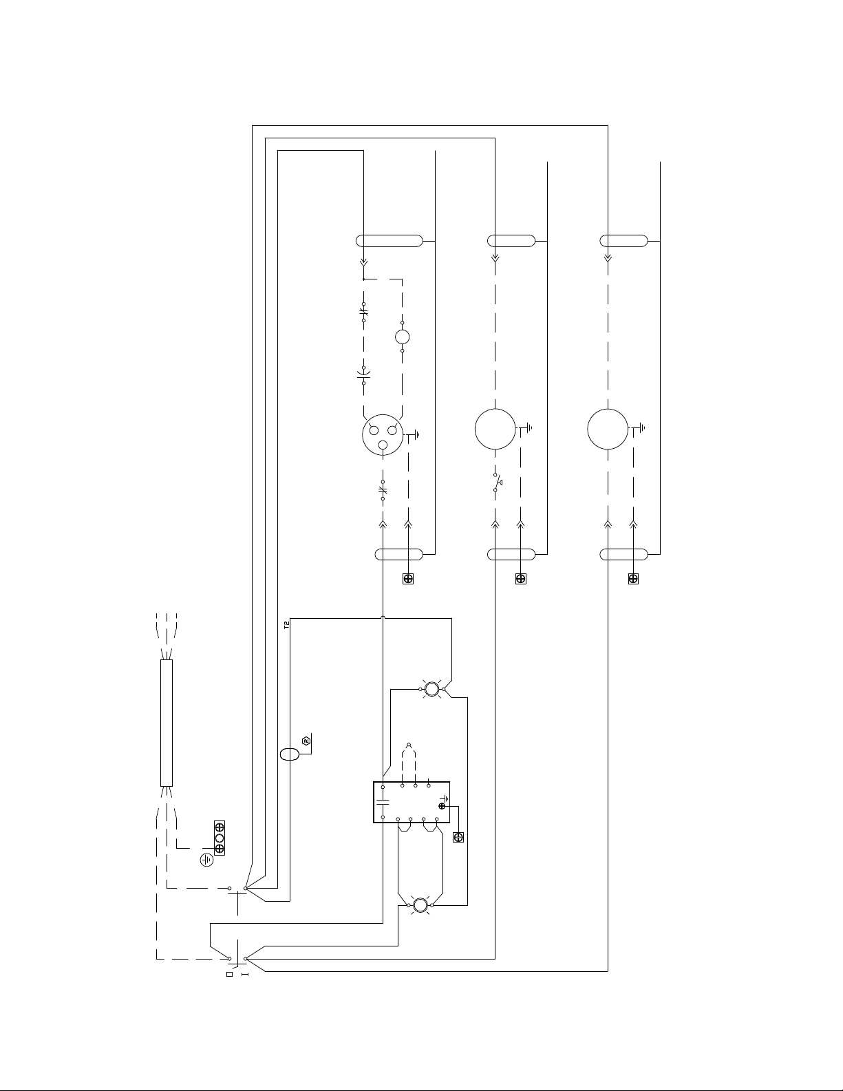
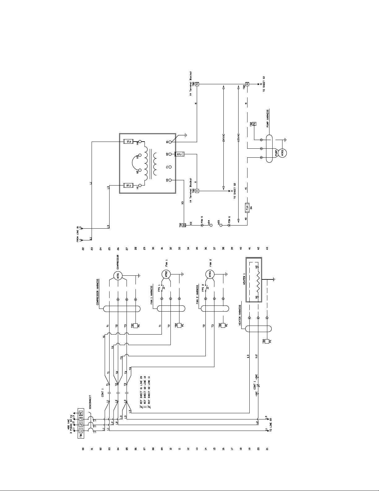
WIRING DIAGRAM - STANDARD CONTROLLER
Models 190/240/280/360/450/540
Sheet1of2
21
20 L2
L3
L1
13
14
15
16
17
18
19
TO LINE 22
12
09
10
11
08
07
06
05
03
04
00
01
02
480 VAC
3 PHASE 60 Hz
L1 L2 L3
L1 L2 L3
TB1 PE
L1
L1
L2
L3
L3
L1
L2
L3
L3
L2
T3
T3
T3
T2
T2
T1
T1
CONT 1
REF SHEET 01 LINE 20
T3
REF SHEET 02 LINE 11
REF SHEET 02 LINE 10
–1NC CONT 1 –2NC
L3
1L2
TB2
PE
T2
T1
T3
T2
T1
TB2
PE
T1
T2
TB2
PE
T3
T2
TB2
PE
HEATER HARNESS
H1 H2
HEATER 1
FPS 2
MTR4 FAN 2
FAN 2 HARNESS
MTR2
FPS 1
FAN 1
FAN 1 HARNESS
MTR1 COMPRESSOR
COMPRESSOR HARNESS
43
42
35
36
37
38
39
40
41
34
31
32
33
30
29
28
27
25
26
22
23
24
X3 N
TO SHEET 02
115VAC
X2
TB2
N
TB2
TB2
X2 TB2
TB2
N
PE
24VAC
X2
N
TB2
X3 FU4 X3
X2
N
FU3
X3 F1 X2 X1
H1 H2 H3 H4
FU2
FU1
L1
L3
L3
L1
L1 L3
FROM LINE 21
L1 L3
H1
H1
H1
H2
H3
H4
208V
230V
460V
FACTORY SET TO 460V
DRAIN 1 HARNESS
PE
N
X2
PE
2
3
5
1
4
6
24VAC
ALM
TEST
24VAC
PE
2
3
5
1
4
6
ALM
TEST
PE
TB2
X
N
DRAIN 2 HARNESS
OPTIONAL DRAIN
Optional Fan
(for 450 – 540 models only)

15
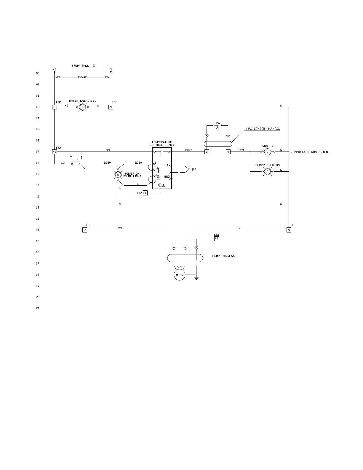
WIRING DIAGRAM - STANDARD CONTROLLER
Models 190/240/280/360/450/540
Sheet2of2
FROM SHEET 01
X3 N
115VAC
00
01
02
03
TB2
X3
DRYER ENERGIZED
X3 GNN
TB2
G
G
TB2 X3
TEMPERATURE
CONTROL BOARD
04
05
06
07
08 X3 2080
X3
2080
POWER ON
PILOT LIGHT
TB2 PE
N
N
N
09
10
11
12
13
14
15
4
3
2
GND
1
–
+
120 VAC
2070 3
100ΩRTD
HPS
HPS SENSOR HARNESS
42071
CONT 1
CN
N
COMPRESSOR ON
COMPRESSOR CONTACTOR
N
N
TB2
N
TB2
PE
PUMP HARNESS
PUMP
MTR3
X3
2
TB2
N
16
17
18
19
20
21

16
WIRING DIAGRAM - STANDARD CONTROLLER
Model 675
Sheet1of2
17
WIRING DIAGRAM - STANDARD CONTROLLER
Model 675
Sheet2of2
Ω RTD

18
WIRING DIAGRAM - ADVANCED CONTROLLER
Models190-540,(460VAC)
Sheet1of2

19
WIRING DIAGRAM - ADVANCED CONTROLLER
Models190-540,(460VAC)
Sheet2of2
20
WIRING DIAGRAM - ADVANCED CONTROLLER
Model675,(460VAC)
Sheet1of2
This manual suits for next models
10
Table of contents
Other SPX Dehumidifier manuals

SPX
SPX HCD Series User manual

SPX
SPX Hankison HPRP Series User manual

SPX
SPX HANKISON HIT Series User manual

SPX
SPX HPD Series User manual

SPX
SPX Hankison GCU Series User manual

SPX
SPX Hankison HPRplus Series User manual

SPX
SPX DELAIR QD 90 User manual

SPX
SPX Pneumatic Products IBP500 User manual

SPX
SPX RDH-HP Series User manual


