SPX RDH-HP Series User manual

RDH-HP Series
Pressure-Swing Desiccant Type Compressed Air Dryers
Models: RDH-HP-715G, RDH-HP-1550G, RDH-HP-5200G
FORM NO.: 3245430 REVISION: 04/2014 READ AND UNDERSTAND THIS MANUAL PRIOR TO OPERATING OR SERVICING THIS PRODUCT.
INSTRUCTION MANUAL
MODELS RATED
FLOW
REFER
AS
MODELS
RDH-HP-715G 715 SCFM 715
RDH-HP-1550G 1550 SCFM 1550
RDH-HP-5200G 5200 SCFM 5200

2
WARRANTY
The manufacturer warrants the product manufactured by it, when properly installed, operated, applied, and maintained in accordance with
procedures and recommendations outlined in manufacturer’s instruction manuals, to be free from defects in material or workmanship for a period
of one (1) year from the date of shipment to the buyer by the manufacturer or manufacturer’s authorized distributor, or eighteen months from the
date of shipment from the factory, whichever occurs first, provided such defect is discovered and brought to the manufacturer’s attention within
the aforesaid warranty period. The manufacturer will repair or replace any product or part determined to be defective by the manufacturer within
the warranty period, provided such defect occurred in normal service and not as a result of misuse, abuse, neglect or accident.
The warranty covers parts and labor for the warranty period. Repair or replacement shall be made at the factory or the installation site, at
the sole option of the manufacturer. Any service performed on the product by anyone other than the manufacturer must first be authorized by
the manufacturer. Normal maintenance items requiring routine replacement are not warranted. Unauthorized service voids the warranty and
any resulting charge or subsequent claim will not be paid. Products repaired or replaced under warranty shall be warranted for the unexpired
portion of the warranty applying to the original product. The foregoing is the exclusive remedy of any buyer of the manufacturer’s product. The
maximum damages liability of the manufacturer is the original purchase price of the product or part.
THE FOREGOING WARRANTY IS EXCLUSIVE AND IN LIEU OF ALL OTHER WARRANTIES, WHETHER WRITTEN, ORAL, OR STATU-
TO RY, AND IS EXPRESSED IN LIEU OF THE IMPLIED WARRANTY OF MERCHANTABILITY AND THE IMPLIED WARRANTY OF FITNESS
FOR A PARTICULAR PURPOSE. THE MANUFACTURER SHALL NOT BE LIABLE FOR LOSS OR DAMAGE BY REASON OF STRICT LI-
ABILITY IN TORT OR ITS NEGLIGENCE IN WHATEVER MANNER INCLUDING DESIGN, MANUFACTURE OR INSPECTION OF THE EQUIP-
MENT OR ITS FAILURE TO DISCOVER, REPORT, REPAIR, OR MODIFY LATENT DEFECTS INHERENT THEREIN. THE MANUFACTURER,
HIS REPRESENTATIVE OR DISTRIBUTOR SHALL NOT BE LIABLE FOR LOSS OF USE OF THE PRODUCT OR OTHER INCIDENTAL OR
CONSEQUENTIAL COSTS, EXPENSES, OR DAMAGES INCURRED BY THE BUYER, WHETHER ARISING FROM BREACH OF WARRANTY,
NEGLIGENCE OR STRICT LIABILITY IN TORT.
The manufacturer does not warrant any product, part, material, component, or accessory manufactured by others and sold
or supplied in connection with the sale of manufacturer’s products.
AUTHORIZATION FROM THE SERVICE DEPARTMENT IS NECESSARY
BEFORE MATERIAL IS RETURNED TO THE FACTORY OR IN-WARRANTY REPAIRS ARE MADE.
CONTENTS
1.0 DESCRIPTION................................................................ 4
2.0 INSTALLATION................................................................ 6
3.0 OPERATION ................................................................. 12
4.0 MAINTENANCE ............................................................ 16
5.0 TROUBLESHOOTING .................................................. 18
6.0 REPLACEMENT PARTS ............................................... 19
3
IMPORTANT:
READ PRIOR TO STARTING THIS EQUIPMENT
A. UNPACKING
This shipment has been thoroughly checked, packed and inspected
before leaving our plant. It was received in good condition by the car-
rier and was so acknowledged.
1. Check for Visible Loss or Damage. If this shipment shows evidence of
loss or damage at time of delivery to you, insist that a notation of this
loss or damage be made on the delivery receipt by the carrier’s agent.
2. Check for Concealed Loss or Damage. When a shipment has been
delivered to you in apparent good order, but concealed damage is
found upon unpacking, notify the carrier immediately and insist on his
agent inspecting the shipment. Fifteen days from receipt of shipment
is the maximum time limit for requesting such inspection. Concealed
damage claims are not our responsibility as our terms are F.O.B. point
of shipment.
B. MOVING CAUTION:
Do not lift by piping. Use lifting lugs or fork lift.
GENERAL SAFETY
INFORMATION
1. Pressurized devices: This equipment is a pressure
containing device. Do not exceed maximum operating
pressure as shown on equipment serial number tag.
Make sure equipment is depressurized before working
on or disassembling it for service.
2. Electrical: This equipment requires electricity to operate.
Install equipment in compliance with national and local
electrical codes. Standard equipment is supplied with
NEMA 4, 4x electrical enclosures and is not intended for
installation in hazardous environments.
Disconnect power supply to equipment when performing
any electrical service work.
3. Breathing Air: Air treated by this equipment may not be
suitable for breathing without further purification. Refer
to OSHA standard 1910.134 for the requirements for
breathing quality air.
4. Noise: Do not operate dryer without mufflers installed.
5. High Velocity Air: Do not stand near mufflers during
tower depressurization.
I. INSTALLATION
1. Install on level surface.
2. Ambient temperature range: 35 to 120°F (1.7 to 49°C)
[ if low ambient package supplied: -10 to 120°F (-23 to 49°C) ]
3. Install purge mufflers if shipped separately.
4. Connect air from compressor to inlet.
• Maximum compressed air temperature: 120°F (49°C)
• Maximum compressed air pressure: Refer to serial number
tag.
• Minimum compressed air pressure: 100 psig (6.9 barg)
5. Connect outlet to air system.
6. Refer to serial number tag for correct voltage. Make electrical
connection to terminal strip in control panel. Connect line to
position 5, neutral to position 6 and ground to position 7.
7. Verify voltage selector switch (115V or 230V). Position should
match voltage on Serial Number Tag.
II. START UP
1. Set or verify controller settings. See section 3.1.1.
2. SLOWLY pressurize unit.
3. Energize dryer by turning on/off switch on. (“I” is on; “O” is off)
4. Adjust purge air flow rate. Turn purge rate valve until Purge
Pressure Gauge reads as shown in the following table.
NOTE: One tower must be purging when setting purge pressure.
MINI INSTRUCTIONS
For complete instructions on installation, operation and maintenance, consult manual.
III. OPERATIONAL CHECKPOINTS
1. Check that dryer is energized (indicating lights are illumi-
nated)
2. MOISTURE INDICATOR - Indicator should be green (Allow
4 hours after start up for indicator to turn green).
3. TOWER PRESSURE GAUGES -
• Tower on line should read line pressure
• Tower off line should read 2 psig (0.14 barg)or less while
purging. If pressure exceeds 2 psig (0.14 barg) replace
purge muffler elements.
NOTE: An extra set of elements is shipped with dryer.
4. PURGE PRESSURE GAUGE - Verify proper setting.
5. CHECK FOR ALARM CONDITION.
IV. DEPRESSURIZATION
Isolate dryer. Run timer until both tower pressure gauges read
0 psig (0 kgf/cm
2
)(test mode may be used to speed up cycle).

4
1.0 DESCRIPTION
Desiccant is regenerated by driving off (desorbing) the water collected
on its surface. Pressure-swing (also called heatless or heaterless
because no outside heat is added) dryers regenerate by expanding a
portion (approximately 14 - 15% at 100 psig, 7 barg) of the dried air to
atmospheric pressure. This “swing in pressure” causes the expanded air
to become very dry (have a very low vapor pressure). This very dry air
(called purge air) plus the stored heat of adsorption allows the moisture
to desorb from the desiccant. The purge air then carries the desorbed
water out of the dryer.
1.1 Function
1.1.1 Dryer
Dual tower regenerative desiccant dryers are an economical and reliable
way to dry compressed air to dew points below the freezing point of wa-
ter (dew points as low as -150°F (101°C) [1 ppb @ 100 psig, 7.0 barg]
are possible) or reduce the moisture content of compressed air when
used in critical process applications.
These dryers continuously dry compressed air by using two identical
towers, each containing a desiccant bed. While one tower is on-stream
drying the compressed air, the other tower is off-stream being regener-
ated (reactivated, i.e., dried out). The towers are alternated on- and
off-stream so that dry desiccant is always in contact with the wet
compressed air. In this way a continuous supply of dry air downstream
is possible.
Desiccant dryers lower the dew point of compressed air by adsorbing the
water vapor present in the compressed air onto the surface of the desic-
cant. Desiccant is a highly porous solid containing extensive surface
area.
Adsorption occurs until the partial pressure of the water vapor in the
air and that on the surface of the desiccant come into equilibrium. As
adsorption occurs, heat is released (referred to as the heat of adsorption)
and is stored in the bed for use during regeneration.

5
8
1
5C 5D 8
7 ) (
2
61
5A
10A 9A 3A 3B 9B 10B
5B
11
INLET
TOWER
4B
TOWER
4A
OUTLET
FIGURE 1A
TOWER 4A DRYING: TOWER 4B REGENERATING
Purge Stream
Process Stream
FIGURE 1B
TOWER 4B DRYING: TOWER 4A REGENERATING
1.2 Description of Operation
1.2.1 Dryer (Refer to Figure 1A.)
Compressed air flows through inlet switching valve (3A) (normally open)
to tower (4A) where the air is dried. After the air is dried it flows through
check valve (5A) and then to the dryer outlet.
A portion of the dry air, the purge stream, branches off from the main air
stream prior to the outlet. The purge stream flow rate is controlled by the
adjustable purge rate valve (6) and the purge orifice (7).
The purge flow, which has been throttled to near atmospheric pressure,
is directed through check valve (5D) to tower (4B). As the purge flow
passes over the desiccant in tower (4B), it removes the water vapor
which was deposited there while the tower was on-line drying. The purge
air then passes through purge and repressurization valve (9B) (normally
closed) and purge muffler (10B) to the atmosphere.
After regeneration, purge and repressurization valve (9B) (normally
open) closes allowing tower (4B) to repressurize slowly. Adequate
repressurization time is allowed so that tower 4B is fully repressurized
before switchover. After a controlled time period, air inlet switching valve
(3B) (normally open) opens and inlet switching valve (3A) (normally
open) closes, purge and repressurization valve (9A) (normally closed)
then opens.
(Refer to Figure 1B.) Tower (4B) is now drying the main air stream while
tower (4A) is being regenerated by the purge air stream. The operation
of the inlet switching (normally open) and purge and repressurization
valves (normally closed) is sequenced by the control system located in
the electrical box.
8
1
5C 5D 8
7 ) (
2
61
5A
10B
9B
3B
3A
9A
10A
5B
11
INLET
TOWER
4B
TOWER
4A
OUTLET
1. Pressure Gauges
2. Purge Pressure Gauge
3. Inlet Switching Valves
4. Desiccant Drying Towers
5. Check Valves
6. Adjustable Purge Rate Valve
7. Purge Orifice
8. Pressure Relief Valves
9. Purge / Repressurization Valves
10. Purge Mufflers
11. Moisture Indicator

6
BC E
D
Desiccant
Dryer
Compressor
Aftercooler
Separator
A
Prefilter(s) Afterfilter
A
Receiver Receiver
(B & C) PREFILTERS - Adequate filtration is required upstream of the
dryer in order to protect the desiccant bed from contamination. The fol-
lowing filtration is recommended:
B - Particulate/Gross Liquid Removal - On heavily contaminated sys-
tems use a gross contaminant filter to remove solids and high inlet liquid
concentrations.
C - Oil Aerosol Removal -On systems with lubricated compressors,
use an oil removal filter to remove oil aerosols and protect desiccant bed
from oil contamination.
(D) DESICCANT DRYER
(E) AFTERFILTER - To ensure downstream air purity (prevent desiccant
dust from traveling downstream) adequate filtration downstream of the
dryer is required. Typically 1 micron filtration is specified although finer
filtration is available.
OR
Oil Vapor Adsorber - Use as an afterfilter to remove oil vapor and its
subsequent taste and odor and to protect down-stream components
from solid particles 0.01 micron and larger.
NOTE: By-pass lines and isolation valves are recommended so that
maintenance work can be performed without shutting off the air supply.
2.2 Physical Location
Dryer must be installed with suitable overhead protection.
2.1 Location in the compressed air system.
NOTE: Air Compressor should be adequately sized to handle air system
demands as well as purge loss. Failure to take this into account could
result in overloading air compressors and/or insufficient air supply
downstream.
NOTE: It is desirable to install dryer where compressed air is at the
lowest possible temperature (downstream of aftercoolers) and the high-
est possible pressure (upstream of pressure reducing valves) without
exceeding the maximum working pressure. (Refer to Figure 2A)
(A) AFTERCOOLER/SEPARATOR - Compressed air entering dryer must
be cooled to at least 120°F (49°C). Use aftercooler and separator if
higher temperatures are present.
NOTE: Installation of a refrigerated dryer ahead of a pressure-swing
desiccant dryer does not increase desiccant dryer capacity or reduce
purge flow requirements. However a cooling unit installed ahead of the
desiccant dryer reduces the inlet air temperature and outlet air dew point.
2.0 INSTALLATION
2.3 Minimum & Maximum Operating Conditions
The compressed air supply inlet should be checked periodically to ensure
that equipment design specifications are not exceeded. Normally the
compressor installation includes intercoolers, aftercoolers, separators,
receivers, or similar equipment which adequately pretreat the com-
pressed air supply in order to avoid excessively high air temperatures
and liquid slugging of downstream equipment.
2.3.1 Compressed air conditions
2.3.1.1 Maximum working pressure: Refer to Serial Number Tag.
WARNING
Do not operate the dryer at pressures above the maximum pressure
shown on the tag.
2.3.1.2 Minimum working pressures: 100 psig (7 barg)
2.3.1.3 Maximum inlet compressed air temperature:
120°F (49°C)
NOTE: If inlet air is higher than 120°F (49°C) the air must be pre-
cooled with an aftercooler.
2.3.2 Ambient temperatures:
Minimum:
Standard units: 35°F (1.7°C)
Units with optional low ambient package: - 10°F (-23°C)
Maximum: 120°F (49°C)
NOTE: If dryer is installed in ambients below 35°F (1.7°C) heat tracing
of the prefilters and inlet piping and valves is necessary to prevent con-
densate from freezing. If installing heat tracing, observe electrical class
code requirements for type of duty specified.
2.4 Mounting
Install dryer on a level pad on floor. Holes are provided in
the floor stand base angles for floor anchors if desired.
NOTE: Floor anchors must be used if area is subject to vibrations.
2.5 Piping
2.5.1 Inlet and Outlet connections
Observe location of inlet and outlet connections as indicated in Figure
2C or 2D and connect inlet and outlet piping.
NOTE: All piping must be supported so as not to bear on the dryers or
filters.
2.5.2 Isolation valves
If isolation valves are installed, it is recommended that gate valves be
used to ensure that dryer is pressurized slowly. This is particularly true
if isolation valves are placed before and after pre- and afterfilters where
rapid pressurization could cause excessive pressure drop across filter
elements.
FIGURE 2A

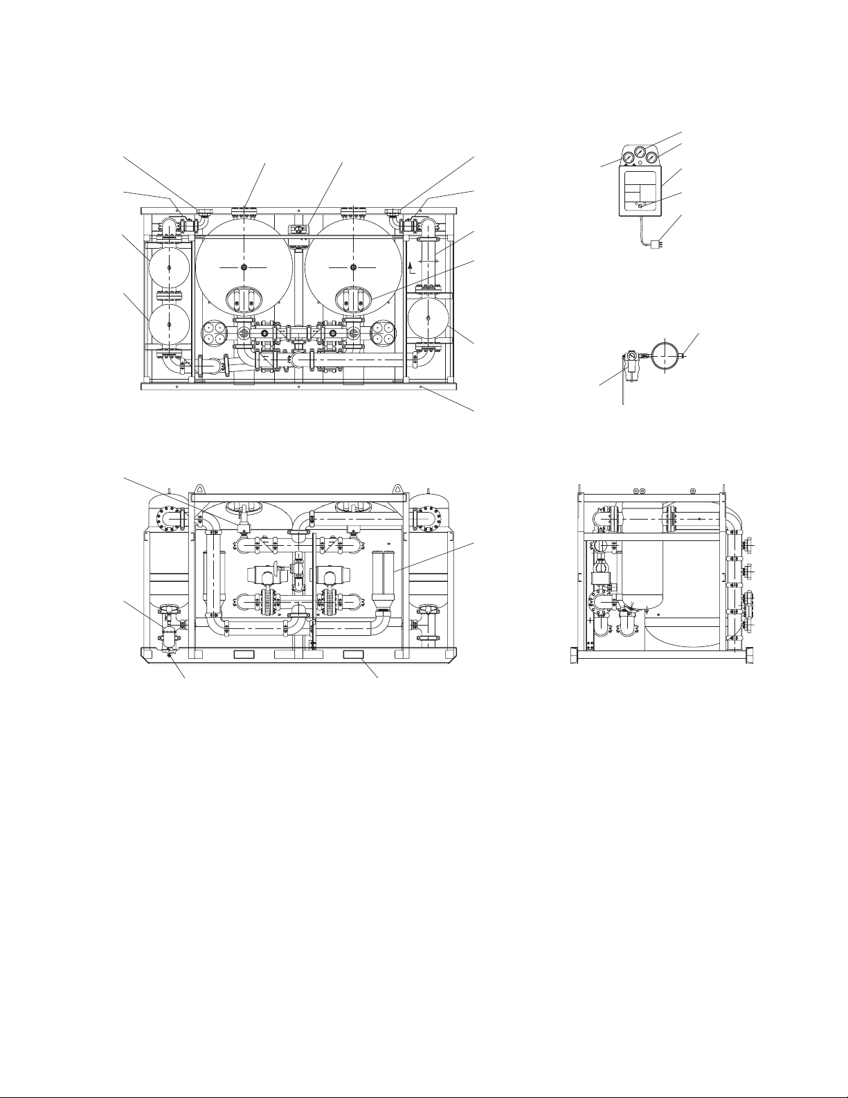
7
Icon idenification
Air Inlet
Air Outlet
Left Tower Pressure Gauge
Right Tower Pressure Gauge
Purge Pressure Gauge
Electrical Entry
Inlet Pressure Gauge
Outlet Pressure Gauge
Automatic Condensate Drain
Purge Muffler
FIGURE 2B

8
FIGURE 2C Model 715G
3.1/4" X 9.1/4" FORKLIFT TUBE
OPENINGS (83mm X 235mm)
3 PLACES
DESICCANT DRAIN
PORT
MOUNTING HOLES
7/8" DIA.
HIGH EFFICIENCY OIL
REMOVAL PREFILTER
AIRLINE AFTERFILTER
AIRLINE PREFILTER
PROCESS AIR OUTLET
NPS 3 BOSS FITTING
TOP VIEW
ELECTRICAL ENCLOSURE
SEE DETAIL
SIDE VIEW
(SEE AC SIDE DETAIL)
RIGHT TOWER
PRESSURE GAGE
PURGE PRESSURE GAGE
PURGE PRESSURE
ADJUSTMENT VALVE
DESICCANT FILL PORT
FRONT VIEW
LEFT TOWER
PRESSURE GAGE
MOISTURE INDICATOR
TOWER PRESSURE
RELIEF VALVE
PROCESS AIR INLET
NPS 3 BOSS FITTING
PURGE MUFFLER
ENCLOSURE DETAIL
(ENLARGED)
3 PRONG MALE
ELECTRICAL PLUG
POWER SWITCH
ELECTRICAL ENCLOSURE
NEMA CLASS 4/4X

9
FIGURE 2D Model 1550G
ELECTRICAL ENCLOSURE
SEE DETAIL A
AIRLINE AFTERFILTER HIGH EFFICIENCY OIL
REMOVAL PREFILTER
SEPARATOR PREFILT ER
TOP VIEW
MOUNTING HOLES
7/8" DIA.
DESICCANT FILL PORT
DESICCANT DRAIN
PORTS
LEFT TOWER
PRESSURE GAUGE
PURGE PRESSURE GAUGE
RIGHT TOWER
PRESSURE GAUGE
ELECTRICAL ENCLOSURE
NEMA CLASS 4/4X
POWER SWITCH
3 PRONG MALE
ELECTRICAL PLUG
DETAIL A
TOWER PRESSURE
RELIEF VALVE
PURGE MUFFLER
PROCESS AIR INLET
NPS 3 BOSS FITTING
CONDENSATE DRAIN
3/4 NAT. HOSE
MALE THREAD
3.1/4" x 9.1/4" FORKLIFT TUBE
OPENINGS (83mm X 235mm)
SIDE VIEW
REAR VIEW OF DRYER
PROCESS AIR OUTLET
NPS 3 BOSS FITTING
MOISTURE INDICATOR
LIFTING LUGS
10
FIGURE 2E Model 5200G
SIDE VIEW
MOISTURE INDICATOR
SECTION B
(ENLARGED)
PILOT AIR REGULATOR
DETAIL A
3 PRONG MALE
ELECTRICAL PLUG
POWER SWITCH
ELECTRICAL ENCLOSURE
NEMA CLASS 4/4X
PURGE PRESSURE GAGE
RIGHT TOWER
PRESSURE GAGE
LEFT TOWER
PRESSURE GAGE
PROCESS AIR OUTLET
NPS 3 BOSS FITTING
4 PLACES
OUTLET SHUT OFF
VALVE NPS 3
4 PLACES
SEE SECTION B
DESICCANT FILL PORT
AIRLINE AFTERFILTER
HF7-76-6F-S
MOUNTING HOLES
1 INCH DIA.
6 PLACES
PURGE MUFFLER
3.1/2" X 9.1/2" FORKLIFT
OPENINGS (90mm X 241mm)
2 PLACES
CONDENSATE DRAIN
3/4 NPS MALE
PIPE THREAD
REAR VIEW
TRIP-L-TRAP
TOWER PRESSURE
RELIEF VALVE
TOP VIEW
B
HIGH EFFICIENCY OIL
REMOVAL PREFILTER
SEPARATOR PREFILTER
PROCESS AIR INLET
NPS 3 BOSS FITTING
4 PLACES
INLET SHUT OFF
VALVE NPS 3
4 PLACES
DESICCANT DRAIN
PORT ELECTRICAL
ENCLOSURE
SEE DETAIL A

11
2.6 Electrical Connections
Standard and Automatic Purge Saving
2.6.1 Power Connections
NOTE: Check Serial Number Tag for correct voltage.
Connect wires to terminal strip. Connect L1 (line) to position 5, L2 (neu-
tral) to position 6, and ground to position 7. Do not make connections to
terminals labeled with grounding symbol or labeled with RS.
Set the voltage selection switch located at the lower edge of the control
board for the proper supply voltage.
Electrical entry is 7/8” dia. hole for 1/2” nominal conduit entry.
2.6.2 Alarm Connections -
Dry contacts for a remote alarm are supplied at terminals 20, 21, 22.
When the unit is energized and no alarms are in effect, continuity should
exist between terminals 20 and 21, with no continuity between terminals
21 and 22. Alarm contact is common for switching failure alarm and
optional high humidity alarm.
Maximum contact rating is:
240 VAC - 5.0 amps
50 VDC - 1.0 amps
NOTE: Check Serial Number Tag for electrical values.
2.7 Provisions for Purge Exhaust
Purge exhaust must be routed through the factory supplied mufflers or
piped to a remote location.
2.7.1 Purge mufflers - If shipped separately, install purge exhaust muf-
flers in the locations shown in Figure 2C, 2D, or 2E.
2.7.2 If purge exhaust is piped to a remote location, choose a pipe size
large enough so that back pressure through the piping is not
created.
WARNING
Do not operate dryer without one of the above measures.
Exhausting air will result in noise levels above OSHA
permissible levels and exhausting gas could potentially
cause harm to persons or property.
2.8 Initial Desiccant Charge
The dryer is shipped complete with desiccant and ready to operate after
piping and electrical connections are made.
FIGURE 2E Electrical Schematic (Standard Dryers)
CUSTOMER
POWER
CONNECTIONS
(SEE NOTE 1)
GROUND
NEUTRAL
LINE 1
2TB-7
2TB-6
2TB-5
1TB-41SS
1TB-3
1TB-2
1FU
125mA
250V
1TB-1
12
T
LOW VOLTAGE
SUPPLY TO SOLID
STATE TIMER AND
CONTROL CIRCUITS
3TB-8 3TB-9
3TB-10
4TB-12
4TB-13
3TB-11
4TB-14
4TB-15
5TB-16
5TB-17 5TB-18
5TB-19
7TB-23
7TB-24
7TB-25
6TB-20
6TB-21
6TB-22
8TB-26
8TB-27
8TB-28
8TB-29
1PS
2PS
CR
CR
CR
POWER OFF/ON SWITCH
SPARE LOAD CONNECTIONS
SOLID STAT E
TIMER AND
CONTROL CIRCUIT
STEP DOWN
TRANSFORMER
120/240 VAC
CONTROL BOARD
INLET VOLTAGE
SELECTOR SWITCH
(SEE NOTE 1)
SOLENOID CIRCUIT FUSE
RIGHT TOWER
INLET SWITCHING
SOLENOID
LEFT TOWER
PURGE/
REPRESSURIZATION
SOLENOID
RIGHT TOWER
PURGE/
REPRESSURIZATION
SOLENOID
LEFT TOWER
INLET SWITCHING
SOLENOID
SPARE GROUND
CONNECTIONS
1SST
1SST
1SOL
2SOL
3SOL
4SOL
1Q
2Q
3Q
4Q
GATE
2FU
1.6A
250V
TO SOLID
STATE
TIMER
AND
CONTROL
CIRCUITS
TO SOLID
STATE
TIMER
AND
CONTROL
CIRCUITS
RIGHT TOWER
SWITCHING FAILURE ALARM
PRESSURE SWITCH
LEFT TOWER
SWITCHING FAILURE ALARM
PRESSURE SWITCH
COMMON ALARM
CONTACTS
(SEE NOTE 2)
2SS
10
9
71
3
4
6
(120) (240)
CUSTOMER
COMMON
ALARM
CONNECTIONS
(SEE NOTE 2)
COMMON ALARM
RELAY
(SEE NOTE 2)
GATE
GATE
GATE
(SEE NOTE 1)
(SEE NOTE 1)
(SEE NOTE 1)
(SEE NOTE 1)
CONTROL CIRCUIT FUSE

12
FIGURE 3B
Standard Control Board
3.0 OPERATION
3.1 Start-up
3.1.1 Controller Settings- Set or verify settings on controller
3.1.1.1 Standard Control Board
WARNING
Enclosure may have live electric parts.
De-energize dryer before opening enclosure.
3.1.1.1.1 Voltage Selection -
Set the voltage selection switch located at the lower edge of the power
board for the proper voltage.
3.1.1.1.2 Dip Switch Settings - (Refer to Table 3A)
NOTE: For ON DIP switch is up; OFF DIP switch is down
To select Test Mode - place switch 5 and 6 in ON position
Right Inlet Solenoid Energized LED
Left Purge/Repressurization Solenoid Energize LED
Right Purge/Repressurization Solenoid Energized LED
Left Inlet Solenoid Energized LED
DIP Switches for Economizer Setting,
Standard or HP selection,
Cycle/Mode selection
Alarm Hook-up
Power Hook-up
Voltage Selection Switch
Soleniod circuit fuse
1.25A 250V
Control circuit fuse
125m A 250V
Tower Pressure Switches Open @40 psig
Close @45 psig
RESET/STEP
BUTTON
HIGH HUMIDITY
ALARM
SWITCHING
FAILURE ALARM
FIXED CYCLE
MODE INDICATORS
LEFT TOWER
REGENERATING
INDICATOR
TEST MODE
INDICATOR
OFF ON
FIGURE 3A
Standard Control Panel
LEFT TOWER
DRYING INDICATOR
RIGHT TOWER
REGENERATING
INDICATOR
RIGHT TOWER
DRYING INDICATOR
PURGE
ECONOMIZER
SETTING
POWER
SWITCH
60 %
50 %
40 %
30 %
100 %
90 %
80 %
70 %

13
3.1.2 SLOWLY pressurize dryer to full line pressure (open inlet isola-
tion valve, outlet isolation valve remains closed).
NOTE: During initial start-up check entire system for leaks. If neces-
sary, depressurize and correct any leaks.
3.1.3 Energize dryer using the power switch located on the control
panel.
NOTE: Switching failure alarm: alarm (light) may be activated if unit is
energized before it is pressurized. To deactivate alarm, allow dryer to
cycle to next step and press the reset button.
3.1.4 Adjust the purge rate valve.
3.1.4.1 Determine:
1) Maximum working pressure (MWP) of dryer from the dryer serial
number tag
2) Air pressure at inlet to dryer
3.1.4.2 Refer to Table 3A for proper purge rate pressure setting at the
conditions found in 3.1.4.1
3.1.4.3 Adjust purge rate valve until purge flow indicator reads re-
quired pressure setting.
NOTE: Adjustment must be made while a tower is purging (air exhaust-
ing from muffler).
IMPORTANT
INSUFFICIENT PURGE AIR WILL EVENTUALLY RESULT IN SATURA-
TION OF DESICCANT BED AND WET AIR DOWNSTREAM. MAKE CER-
TAIN THAT CYCLE TIME, PURGE ECONOMIZER SWITCH, AND PURGE
PRESSURE ARE CORRECTLY SET.
3.1.5 Establish normal flow through dryer (open outlet isolation
valve). Close air by-pass valve if present.
NOTE: When dew points below -40°F (-40°C) are required, the dryer
must be run with an inlet flow rate of less than 50% of maximum until
the desired dew point is attained. Depending on the initial dryness of
the desiccant, this can take as long as 2 to 3 days. This stabilization
period is required on initial startup, after dryer has been shutdown
for extended periods of time, or after dryer maintenance (desiccant
change, etc.).
3.1.6 With the inlet pressure to the dryer at its minimum level, read-
just the purge pressure as determined in 3.1.4.
NOTE: Adjustment must be made while a tower is purging (air exhaust-
ing from muffler).
3.2 Operational Check Points
3.2.1 Standard Unit
3.2.1.1 Power to unit -
Check periodically that there is power to the unit (indicating lights il-
luminated).
3.2.1.2 Moisture Indicator -
Every four hours check moisture indicator. Indicator should be green.
Outlet relative humidity of the desiccant dryer is indicated by the color
change humidity indicator. Green indicates a R.H. below 3% and yellow
indicates a R.H. above 3%. Table 3C (page 16) indicates outlet dew point
when moisture indicator changes from green to yellow at various inlet
temperatures.
NOTE: During start-up the indicator may be yellow, however, it should
begin to change to green within four hours.
3.2.1.3 Purge Flow Indicator -
Every four hours check the purge pressure and adjust as required. Ad-
justment should be made when the inlet pressure to the dryer is at its
minimum level.
NOTE: Adjustment must be made while a tower is purging (air exhaust-
ing from muffler).
Units with Standard Board Operation
3.2.1.4 Alarms
Periodically check for flashing red alarm light. Alarm light will flash if
either tower fails to pressurize or depressurize to the required levels at
the proper time or if optional high humidity alarm indicates high exiting
dewpoint.
NOTE: Alarm will activate if dryer is energized without being pressur-
ized. If this occurs allow dryer to cycle to next step and press reset
button.
NOTE: Alarm light will continue to flash even if fault clears. To clear
alarm, press reset button.
NOTE: If the tower being regenerated fails to repressurize, the dryer
will not switch towers. The switching failure alarm will be activated and
the dryer will remain in this mode until the tower repressurizes.
Switching Failure
The switching failure alarm operates by sensing tower pressures after
tower changeover. If towers have failed to pressurize or depressurize to
the required levels, an alarm condition exists. The alarm light blinks while
the alarm condition exists. Depressing the reset switch will extinguish the
light, but will not interrupt the drying cycle.
If the tower being regenerated fails to repressurize, the dryer will not
switch towers. The switching failure alarm will be activated and the dryer
will remain in this mode until the tower repressurizes.
3.2.1.5 Tower Status Lights -
Illuminated light indicates which tower is on-line drying or off-line re-
generating.
3.2.1.6 Tower pressure gauges
3.2.1.6.1 Periodically check tower pressure gauges to verify that tower
pressure gauge of tower on-line reads line pressure and tower
pressure gauge of tower off-line reads below 2 psig.
NOTE: Read off-line tower gauge when tower is purging (air exhaust-
ing from muffler)
3.2.1.6.2 Check mufflers for back pressure
Excessive back pressure may result due to the accumulation of dust in
the muffler. This sometimes occurs after start-up because of dusting of
the desiccant during tower filling and dryer transport.
If the tower pressure gauge of the off-stream tower rises out of the black
area on the gauge dial, muffler elements should be replaced. A set of
purge exhaust muffler replacement elements is supplied with the dryer.

14
3.2.3 All MODELS - Determine if air control valves are operating and
sequencing correctly.
3.2.3.1 Inlet switching and purge/repressurization valves.
1) Tower pressure gauge of tower on-line should read line pressure. No
air should be leaking from purge/repressurization valve of the on-line
tower.
2) Tower pressure gauge of tower off-line should read below 2 psig while
tower is purging. If excessive purge air is exhausting during purge
cycle, inlet valve may have failed to close or a check valve may be
sticking.
3.2.3.2 Check valves
Check valve sticking will result in excessive air discharge through a muf-
fler. If excessive air is discharged through the muffler on the left, check
if valve 5a or 5d is sticking. If excessive air is discharged through the
muffler on the right, check if valve 5b or 5c is sticking.
3.3 Shut Down
3.3.1 Depressurize dryer
3.3.1.1 Open by-pass valve (if one is installed) and close inlet and
outlet isolation valves.
3.3.1.2 Run timer through a tower change cycle until pressure gauges
on both towers read 0 (test mode may be used to speed this
up).
3.3.2 De-energize dryer
Turn dryer off using on-off switch (indicating lights extinguished).
3.4 Loss of Power
Control valves are designed so that upon loss of power the air dryer
is capable of drying air until the desiccant exposed to the air flow is
saturated.
3.5 Verify that dryer is operating within design parameters
3.5.1 Maximum working pressure:
Refer to Serial Number Tag to determine maximum working pressure
of dryer.
WARNING
Do not operate dryer at pressures above the maximum pressure shown
on the tag.
3.5.2 Minimum working pressures: 100 psig (7 barg)
15
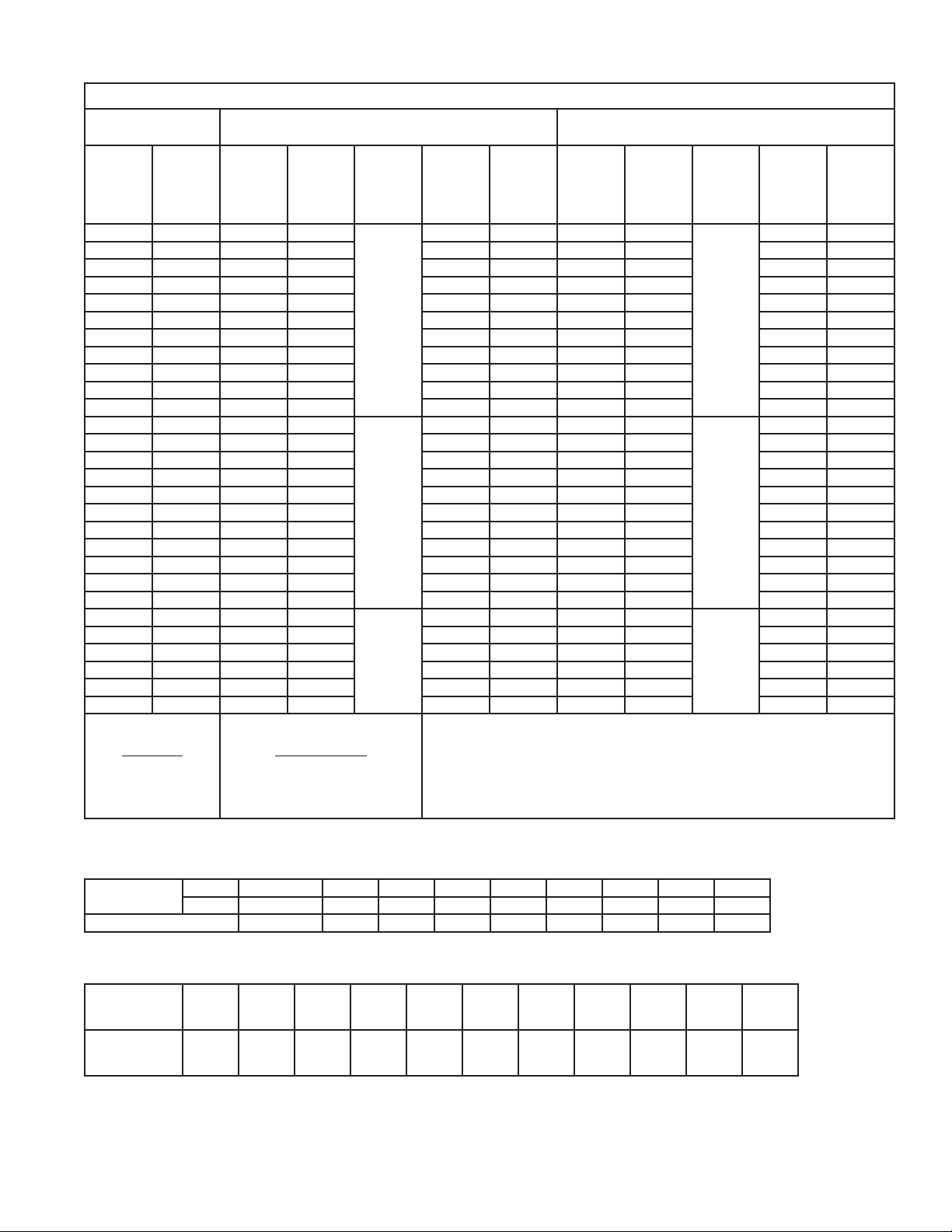
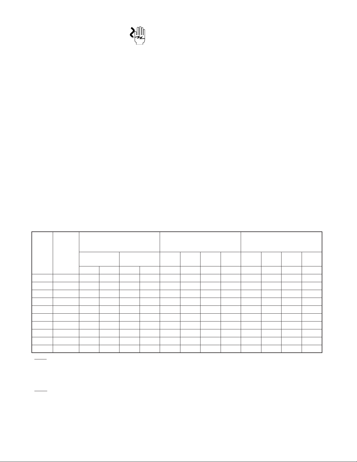
TABLE 3A
Model RDH-HP
Inlet Temperature
100°F
Outlet Pressure Dew Point: -40°F
10 Minute Cycle
Outlet Pressure Dew Point: -100°F
4 Minute Cycle
Inlet
Pressure
(psig)
Inlet
Pressure
Correction
Factor
*
Purge
Time
(seconds)
Repress
Time
(seconds)
Timer
board DIP
Switch
Settings
Purge
Orifice
Pressure
(psig)
Maximum
Purge
Flow
Factor
**
Purge
Time
(seconds)
Repress
Time
(seconds)
Timer
board DIP
Switch
Settings
Purge
Orifice
Pressure
(psig)
Maximum
Purge
Flow
Factor
**
350 1.78 139 155
1 = OFF
2 = ON
3 = OFF
4 = ON
5 = OFF
6 = ON
42 0.166 29 85
1 = ON
2 = ON
3 = OFF
4 = ON
5 = ON
6 = OFF
89 0.318
340 1.76 139 155 43 0.168 29 85 90 0.322
330 1.73 139 155 44 0.170 29 85 92 0.327
320 1.71 139 155 44 0.173 29 85 93 0.333
310 1.68 139 155 45 0.176 29 85 95 0.337
300 1.66 139 155 46 0.178 29 85 97 0.342
290 1.63 139 155 47 0.181 29 85 98 0.348
280 1.60 139 155 48 0.184 29 85 100 0.353
270 1.58 139 155 49 0.188 29 85 102 0.360
260 1.55 139 155 50 0.191 29 85 104 0.366
250 1.52 139 155 51 0.194 29 85 106 0.373
250 1.52 174 120
1 = OFF
2 = OFF
3 = OFF
4 = ON
5 = OFF
6 = ON
39 0.155 42 72
1 = OFF
2 = OFF
3 = OFF
4 = ON
5 = ON
6 = OFF
70 0.257
240 1.49 174 120 40 0.158 42 72 72 0.262
230 1.46 174 120 41 0.162 42 72 74 0.268
220 1.43 174 120 42 0.165 42 72 75 0.273
210 1.40 174 120 43 0.169 42 72 77 0.279
200 1.37 174 120 44 0.172 42 72 79 0.286
190 1.34 174 120 46 0.177 42 72 81 0.293
180 1.30 174 120 47 0.181 42 72 84 0.300
170 1.27 174 120 48 0.186 42 72 86 0.308
160 1.23 174 120 50 0.191 42 72 89 0.317
150 1.20 174 120 52 0.197 42 72 92 0.326
150 1.20 234 60 1 = OFF
2 = OFF
3 = OFF
4 = OFF
5 = OFF
6 = ON
36 0.146 66 48 1 = OFF
2 = OFF
3 = OFF
4 = OFF
5 = ON
6 = OFF
55 0.208
140 1.16 234 60 38 0.151 66 48 57 0.214
130 1.12 234 60 39 0.156 66 48 59 0.222
120 1.08 234 60 41 0.162 66 48 62 0.230
110 1.04 234 60 43 0.168 66 48 65 0.239
100 1.00 234 60 45 0.175 66 48 68 0.249
Dryer Model
RDH-HP-715
RDH-HP-1550
RDH-HP-5200
Inlet Flow Rating
@ 100 psig (scfm)
715
1550
5200
* (Inlet Flow rating @ P) =
(Inlet Pressure Correction factor @ P) X (Inlet Flow Rating @ 100 psig)
** (Maximum Purge Flow @ P) =
(Maximum Purge Flow Factor @ P) X (Inlet Flow Rating @ 100 psig)
TABLE 3C Outlet pressure dew points at moisture indicator color change
INLET
TEMPERATURE
°F
°C
35
1.7
40
4.4
50
10.1
60
15.6
70
21.1
80
26.7
90
32.2
100
37.8
110
43.3
120
48.9
OUTLET P.D.P. °F
°C
-34
-36.7
-28
-33.4
-22
-30.0
-16
-26.7
-10
-23.4
-4
-20.0
3
-16.1
9
-12.8
15
-9.5
21
-6.1
TABLE 3B Inlet Temperature Correction Factor
INLET
TEMPERATURE
°F 100 and below 105 110 115 120 125 130 135 140
°C 38 and below 41 43 46 49 52 54 57 60
MULTIPLIER 1.0 0.98 0.96 0.93 0.91 0.85 0.81 0.76 0.70
16
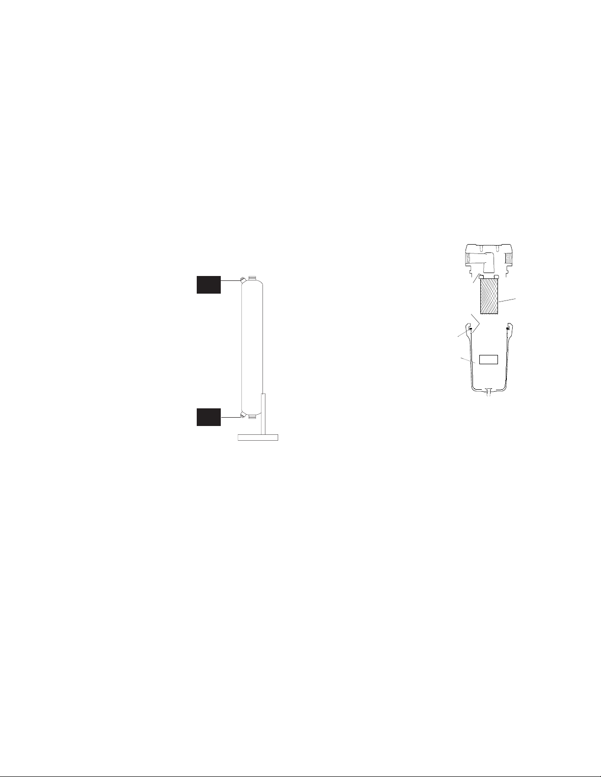
4.2 Pilot Air Filter - Element Replacement -
Models 370 scfm and larger
4.2.1 Frequency of replacement -
Pilot air filter contains a filter element which should be changed yearly
or sooner if pressure drop across cartridge prevents valves from actu-
ating. Pilot air pressure must not drop below 60 psig (4.2 kgf/cm2).
4.2.2 Procedure for element replacement.
Follow instructions supplied with replacement element.
WARNING
THIS SEPARATOR IS A PRESSURE CONTAINING DEVICE. DEPRES-
SURIZE BEFORE SERVICING. IF SEPARATOR HAS NOT BEEN DEPRES-
SURIZED BEFORE DISASSEMBLY, AN AUDIBLE ALARM WILL SOUND
WHEN THE BOWL BEGINS TO BE REMOVED FROM THE HEAD. IF THIS
OCCURS, STOP DISASSEMBLY, ISOLATE AND COMPLETELY DEPRES-
SURIZE SEPARATOR BEFORE PROCEEDING.
1. Shut off air supply.
2. Depressurize Dryer.
3. Remove bowl.
a. Push bowl up, turn bowl
1/8th turn to your left,
and pull bowl straight down
4. Clean filter bowl
5. Replace element
a. Pull off old element and
discard
b. Make certain o-ring inside
top of replacement element
is in place and push element
onto filter head.
NOTE: Make certain o-ring is generously lubricated.
6. After making certain that bowl o-ring is in place, reassemble bowl
to head.
NOTE: Wave spring ends should be pointed down to prevent the wave
spring from interfering with reassembly.
4.3 Fuse Replacement
4.3.1 Fuses are located on board in electrical enclosure. See figure
3B for Standard Control Board and 3C for Automatic Purge Sav-
ing System.
4.0 MAINTENANCE
FIGURE 4B
Element O-ring
Replacement
Element
Bowl O-ring
Wave Spring
Spacer
WARNING
The heatless desiccant dryer is a pressure containing device. Depressurize
before servicing. (See Section 3.3)
4.1 Desiccant Replacement
NOTE: The use of the correct replacement desiccant is necessary for
proper dryer operation. Never use hygroscopic salts of the type com-
monly used in “deliquescent” type dryers.
4.1.1 Frequency of desiccant replacement
Desiccant should be replaced whenever the required dew point cannot
be maintained while the dryer is being operated within its design condi-
tions and there are no mechanical malfunctions. Refer to section 5.0 for
troubleshooting hints.
NOTE: Desiccant life is determined by the quality of the inlet air. Proper
filtering of the inlet air will extend the life of the desiccant.
Typically desiccant life is 3 to 5 years.
4.1.2 Procedure for Desiccant Charge Replacement
4.1.2.1 Depressurize and de-energize the dryer. (See section 3.3)
4.1.2.2 Remove the fill and drain plugs
from desiccant tower and drain
the spent desiccant. Place a
container at the base of the
vessel to collect the desiccant.
If necessary tap the sides of the
vessels with a rubber mallet to
loosen desiccant.
4.1.2.3 Replace the drain plug using
teflon tape sealant or equivalent.
4.1.2.4 Fill the desiccant drying tower as
full as possible with dry desic-
cant. Do not tamp desiccant.
4.1.2.5 Replace the fill plug using teflon
tape sealant or equivalent.
4.1.2.6 Repeat this procedure for the
other tower.
4.1.3 Insuring desiccant dryness
4.1.3.1 Replacement desiccant is shipped in air tight containers. Keep
the covers on these containers tightly closed until use to avoid
moisture contamination. If desiccant is exposed to air it can be
heated in an oven at 400°F (204°C) for four hours before use,
or the procedure in 4.1.3.2 can be used.
4.1.3.2 If the dryer is not refilled with dry desiccant, it will be necessary
to operate the dryer with an inlet flow rate of less than 50% of
maximum to dry the desiccant. To do this, set the Economizer
Switch for 100%, and the purge pressure for 45 psig. (3.2 kgf/
cm2)
4.1.3.3 Purge mufflers should be changed annually.
4.1.3.4 Valve(s) should be checked annually.
DRAIN
PLUGS
FILL
PLUG
FIGURE 4A
DRAIN
PLUGS
17
Test Mode
TABLE 4B
TOWER STATUS VALVE POSITION SOLENOID/TERMINALS
ENERGIZED
(light illuminated)
STEP
NUMBER
WHAT
OCCURS
MODE PRESSURE L
P/R
L
IN
R
P/R
R
IN
L
P/R
L
IN
R
P/R
R
IN
LT RT LT RT
Start D D LP LP C O C O
1 R IN closes D - LP LP C O C C E
2 (1) R P/R opens D R LP <2 C O O C E E
3 No change D R LP <2 C O O C E E
4 (2) (3) R P/R closes D - LP REP C O C C E
5 R IN opens D D LP LP C O C O
6L IN closes - D LP LP C C C O E
7 (1) L P/R opens R D <2 LP O C C O E E
8 No change R D <2 LP O C C O E E
9 (2) (3) L P/R closes - D REP LP C C C O E
NOTES:
(1) Close purge rate valve during this step to check for any valve leaks. No air should exhaust through the muffler. If air is exhausting through the muffler, check all valves for leaks.
After testing for leaks or fixing any leaks, be sure to open the purge pressure valve and reset the purge pressure.
(2) Do not go to the next step until the tower is repressurized.
(3) Switching failure alarm circuit is energized during this step (alarm light should flash until pressure exceeds 40 psig).
CODES:
R IN - Right inlet valve D - Drying E - Energized
R P/R - Right purge/repressurization valve R - Regenerating
L IN - Left inlet valve LP - Line Pressure
L P/R - Left purge/repressurization valve <2 - Less than 2 psig
LT - Left tower REP - Repressurizing
RT - Right tower C - Closed
O - Open
4.4 Test Mode
WARNING
Enclosure contains electricity.
Use caution when working inside box.
4.5.1 Test Mode - Standard Control Panel
4.5.1.1 Wait until point in cycle when right tower is drying and left
tower has completed regeneration and repressurization (both
towers at full line pressure).
4.5.1.2 De-energize dryer (on/off switch off, “O”); Select Test Mode by
placing DIP switches 5 and 6 (found inside enclosure) in the ON
(up) position; Re-energize dryer (1) (2).
4.5.1.3 Use Reset/step button to step through the operating cycle in the
order shown in Table 4B.
4.5.1.4 Complete all 9 steps, allow the left tower to fully repressurize
and de-energize dryer. (1) (3).
4.5.1.5 Reset DIP switches 5 and 6 to operating mode desired (10 min.
cycle - 5 is OFF, 6 is ON or 4 min. cycle - 5 is ON, 6 is OFF); Re-
energize dryer.
(1) Do not de-energize dryer unless both towers are at line pressure.
(2) If Test Mode is selected without de-energizing dryer, Test Mode light
will blink until tower on line has completed drying. Dryer will then enter
Test Mode and light will glow steadily.
(3) If another operating mode is selected without de-energizing dryer and
before all 9 steps are completed, selected mode light will blink and dryer
will automatically complete a cycle. Dryer will then operate in selected
mode and light will glow steadily. You may also use the Reset/step but-
ton to manually step through the cycle until the left tower drying light
illuminates and pressing the Reset/step button will not advance through
further steps.
18
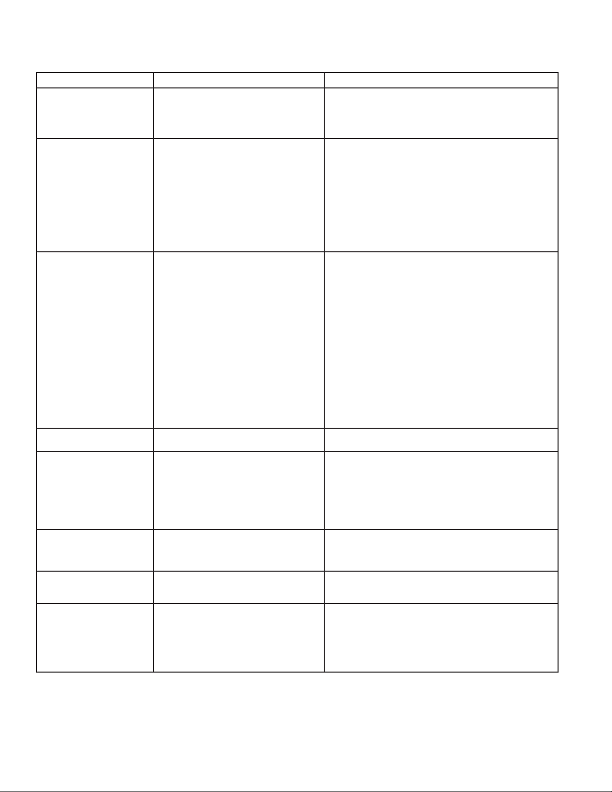
5.0 TROUBLESHOOTING
SYMPTOM POSSIBLE CAUSE(S CORRECTIVE ACTION
5.1 Indicator lights not illuminated No power to unit
On/Off Switch off
Switch malfunctioning
Check voltage at terminal board.
Turn on.
Replace switch.
5.2 Moisture Indicator turns yellow
(elevated outlet dew points)
Maximum flow being exceeded
Design conditions being exceeded
Desiccant not adsorbing
a. Useful service life has ended
b. Desiccant is contaminated
(e.g. with oil)
c. Premature exhaustion (saturated with water)
Refer to Table 3A to determine maximum flow.
Refer to Section 3.5 to determine if dryer is being operated within its design
limitations.
Change desiccant.
Take corrective action. Refer to Section 2.1 to determine proper prefiltration
then change desiccant.
Refer to 5.3 for corrective action. Desiccant beds may be reactivated by running
at reduced flow until desired outlet dewpoint is achieved.
5.3 Desiccant being exhausted
prematurely
Insufficient purge rate
a. Improper purge rate
b. Tower not completely depressurized during
purge cycle (Tower pressure gauge should read
lower than 2 psig)
1. Clogged exhaust muffler
2. Purge valve won’t open
3. Check valve stuck open
Insufficient purge time
a. Improper set points
b. Faulty Timer
Refer to Section 3.1.4 to determine correct Purge Pressure Indicator Setting.
Replace muffler inserts.
Check power to valve to determine if valve or timer at fault.
Check pilot air line for obstruction.
Repair valve.
Refer to Section 3.1.1 to determine correct Economizer Switch and Cycle Set-
tings.
Refer to Section 3.2.3 to verify proper time sequence.
5.4 Tower fails to pressurize to line
pressure
Purge repressurization valve won’t close
Excessive downsteam air demand
Check valve for obstruction. This valve is normally closed.
Check pilot solenoid valve and pilot air line for obstruction.
5.5 Tower fails to depressurize to less
than 2 psig
Purge rate valve open too far
Clogged muffler
Check valve stuck open
Purge repressurization valve won’t open
Check Section 3.1.4 for purge rate indicator setting.
Replace muffler.
Repair valve.
Check power to valve to determine if valve or timer is at fault. Check pilot valve,
pilot air line, and purge repressurization valve for obstruction.
5.6 Excessive purge air is discharged
during purge cycle
Inlet valve won’t close
Check valve sticking
Check power to valve to determine if valve or timer is at fault.
Check valve for obstruction. Check pilot valve and pilot air line for obstruction.
Repair Valve
5.7 Excessive desiccant dust
downstream
Faulty timer
Purge rate valve closed
Refer to Section 3.2.3 to verify proper time sequence.
Refer to Section 3.1.4 to determine Correct Purge Pressure setting.
5.8 Switching Failure
Unit did not depressurize in time
(24 sec) or below 10#
Unit did not repressurize in time
(24 sec) or not above 40#
Clogged mufflers, faulty check valve, faulty inlet valve or
purge valve, or faulty pressure switch.
Make sure dryer has air pressure, check purge pressure
setting, faulty purge valve, or faulty pressure switch.
Replace mufflers or defective parts.
Provide proper air pressure. Replace defective parts. Set purge pressure per
section 3.1.4.

19
Description Model HP-715G Model HP-1550G Model HP-5200G Quantity
Power On/Off Selector Switch 3158486 3158486 3158486 1
Pressure Switch 7417131 7417131 7417131 1
Switching Valve Pilot Solenoid Valve (coil only) 4009808 4009808 4009808 2
Purge Pilot Solenoid Valve (coil only) 4009808 4009808 4009808 2
Switching Valve Pilot Solenoid Valve Rebuild Kit 3153703 3153703 3153703 1
Moisture Indicator 4003167 4003167 4003168 1
Pressure Gauge, 0 - 400PSIG 4011115 4011115 4011115 3
Pressure Gauge, 0 - 100PSIG 4011100 4011100 4011100 1
Purge Muffler Replacement Core 3097672 — — 1
Purge Muffler Replacement Core — 72378 72378 8
Aftercooler Air Filter-Silencer Replacement Core 3211091 3211091 3211091 1
Aftercooler Temperature Gauge 4011137 4011137 4011137 1
Packaged Oil (for Aftercooler option) 3164064 3164064 3164064 1
Filtration Replacement Elements Quantity per Dryer
3174776, High Efciency Oil Removal Prelter (Grade 5) 2 3 11
3174855, Air Line Afterfilter (Grade 7) 2 3 11
3174934, Separator Prefilter (Grade 9) 2 3 11
Desiccant Quantity per Dryer
3153517, 10# container 2 — —
7405937, 17# container 2 2 —
3146257, 50# container 2 — —
3146259, 150# container — 12 4
3146260, 350# container 2—4
3146261, 2000# sack — — 2
6.0 REPLACEMENT PARTS

RDH-HP SERIES
Pressure-Swing
Desiccant Type
Compressed Air Dryers
Models: RDH-HP-715G
RDH-HP-1550G
RDH-HP-5200G
SPX
1000 Philadelphia Street
Canonsburg, PA 15317-1700 U.S.A.
P: (724) 745-1555
F: (724) 745-6040
www.rentaldryers.com
Improvements and research are continuous at SPX.
Specifications may change without notice.
ISSUED 04/2014 Form No.: 3245430 Revision: A
COPYRIGHT ©2014 SPX Corporation
This manual suits for next models
3
Table of contents
Other SPX Dehumidifier manuals

SPX
SPX DELAIR QD 90 User manual

SPX
SPX Hankison GCU Series User manual

SPX
SPX HANKISON HES Series User manual

SPX
SPX HPD Series User manual

SPX
SPX HCD Series User manual

SPX
SPX HANKISON HIT Series User manual

SPX
SPX Hankison HPRP Series User manual

SPX
SPX Hankison HPRplus Series User manual

SPX
SPX Pneumatic Products IBP500 User manual
Popular Dehumidifier manuals by other brands


Seaira Global
Seaira Global WatchDog 900c Installation and operation manual

LG
LG D451WH owner's manual

ICP
ICP iDRY Instructions for installation and operation

Trotec
Trotec TTK 24 E operating manual

Olimpia splendid
Olimpia splendid SeccoReale Instructions for installation, use and maintenance

omi
omi ED HP40 Instruction and maintenance manual


