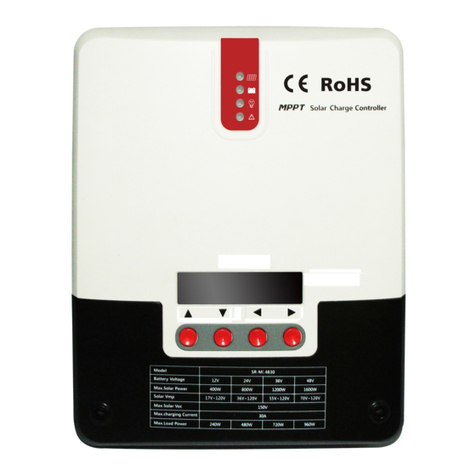
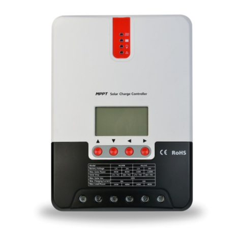
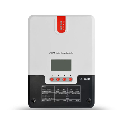
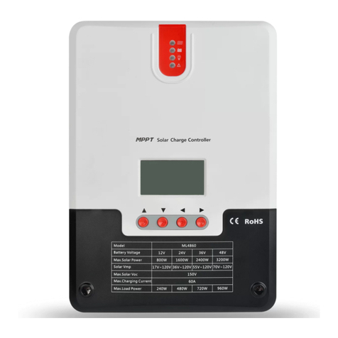
Srne MD Series User manual

Manual version: V1.02 Subject to change without notice
User Manual of MPPT DC Charge
Controller for Solar Energy and Generator
Code: 108260

Dear users:
Thank you for choosing our products!
Safety Instructions
1. Since the applicable voltage of the controller exceeds the safety limit of human body,
please read the manual carefully before operation and operate it only after the safety
operation is trained.
2. Since no part is required to be maintained or repaired inside the controller, please do
not disassemble and repair the controller.
3. Please install the controller indoors to avoid exposure of components and keep water
away from the controller.
4. Since the cooling fin will be very hot during operation, please mount the controller in a
well-ventilated place.
5. Suitable fuse or circuit breaker is recommended to be equipped outside the controller.
6. Before installing and adjusting the wiring of the controller, be sure to disconnect the
wiring of the photovoltaic array and the fuse or circuit breaker near the accumulator
battery terminals.
7. After installation, check whether all wiring is tightly connected to avoid the danger of
heat accumulation due to loose connection.
Warning: Indicating dangerous operation, and safety preparation is required
before operating.
!
Contents
01 02
1. Product Introduction------------------------------------------------------------------------------
1.1 Product overview------------------------------------------------------------------------------
1.2 Product features-------------------------------------------------------------------------------
1.3 Interface description--------------------------------------------------------------------------
1.4 Introduction of maximum power point tracking--------------------------------------------
1.5 Introduction of charging stage---------------------------------------------------------------
1.5.1 Charging for lead-acid battery--------------------------------------------------------
1.5.2 Charging for lithium battery-----------------------------------------------------------
2. Product Applications----------------------------------------------------------------------------
2.1 Specification and parameter-----------------------------------------------------------------
2.2 Default parameters of battery type----------------------------------------------------------
2.3 Definition and description of indicator lights-----------------------------------------------
2.3.1 Status description of indicator lights-------------------------------------------------
2.3.2 Indicator light of solar panel-----------------------------------------------------------
2.3.3 Indicator light of generator------------------------------------------------------------
2.3.4 Indicator light of backup battery------------------------------------------------------
2.3.5 Indicator light of backup battery types-----------------------------------------------
2.4 Button-------------------------------------------------------------------------------------------
2.5 RS485 communication --------------------------------------------------------------
2.6 CAN communication interface
----
-----------------------------------------------------------
2.7 Bluetooth communication --------------------------------------
2.8 CAN communication -------------------------------------
2.9 TTL communication interface- -- -----------------------------------------------------------
3. Common Problems and Solutions------------------------------------------------------------
4. Installation-----------------------------------------------------------------------------------------
4.1 Installation precautions-----------------------------------------------------------------------
4.2 Reference for wire and fuse selection------------------------------------------------------
4.3 Installation and wiring-------------------------------------------------------------------------
5. Product Dimensions-----------------------------------------------------------------------------
Attention: Indicating destructive operation.
Tips: Indicating suggestions and tips to the operator.
03
03
03
04
04
06
06
07
08
08
09
09
09
09
10
10
10
10
11
11
11
11
12
12
13
13
13
14
16
2.10 Voltage compensation interface of backup battery- -------------------------------------
2.11 Temperature sampling interface of backup battery--------------------------------------
2.12 Ignition signal interface --------------------------------------------------------------------
12
12
12
--------
------------------------------
-
--
--
-------------------------------------

03
1. Product Introduction
03 04
1.1 Product overview
Based on multi-phase synchronous rectification technology and advanced MPPT control algorithm,
the MD Series MPPT DC charge controller for solar energy and generator adopts fully digital and
intelligent design. Thus, it achieves advantages such as great response speed and reliability and
reaches high industrialization standards. The multi-phase synchronous rectification technology ensures
super conversion efficiency at any charging power, significantly improving the energy utilization of the
system. The PowerCatcher maximum power point tracking technology leads the industry and achieves
the maximum energy tracking of solar panels. That makes it possible for the panel to rapidly and
precisely track the maximum power point of solar battery in any condition and obtain the maximum
energy of solar panels in real-time.
The product belongs to the DC/DC intelligent charger that applies to vehicle or ship systems. It is
applied to a dual battery system integrating the respective advantages of generator and photovoltaic
power generation. In this case, the system adopts the combination of charging methods with ingenious
design, which effectively ensures enough power at any time. The backup battery could be charged by
either or both of the solar energy and generator.
1.4 Introduction of maximum power point tracking
The MPPT (Maximum Power Point Tracking) system is an advanced charging technology, which
achieves more energy output from the solar batteries by adjusting the operating state of the electrical
modules. Due to the nonlinearity of the solar battery array, there is a maximum energy output point
(maximum power point) on its curve. The traditional controller (switching charging technology and
PWM charging technology) cannot charge the battery continuously at the point, so it cannot obtain the
maximum energy of the solar panel. Instead, the solar controller with MPPT can always track the
maximum power point of the array, so as to charge the battery with the maximum energy. For
example, for the 12V solar system, since the peak-to-peak voltage (Vpp) of the solar battery is about
17V, while the battery voltage is about 12V, therefore, when the charge controller is charging the
battery, the voltage of the solar battery is generally about 12V, that is, the solar battery does not fully
exert its maximum power. The MPPT controller can overcome the problem. It could adjust the input
voltage and current of the solar panel in real-time to reach the maximum input power. Compared with
the traditional PWM controller, the MPPT controller can exert the maximum power of the solar battery,
so it can provide a larger charging current. Generally, the MPPT controller can improve the energy
utilization rate by 15%~20% more than the PWM controller.
Applied with the PowerCatcher maximum power point tracking technology, the controller could still
track the maximum power point of the solar battery in complex conditions. Compared with traditional
MPPT technology, it has better response speed and tracking efficiency, and its efficiency could reach
up to 99.9%.
Applied with the design of multi-phase synchronous rectification for step-up/down circuitry, the
controller owns great DC/DC conversion efficiency whether in high/low power, which could reach up to
98%.
Various types of backup batteries are supported such as sealed, gel, flooded, lithium, and custom.
Various types of generators are supported such as intelligent and traditional generators, and the
controller could automatically identify the generator types by the ignition signal.
Applied with various charging modes such as photovoltaic charging the backup battery individually,
generator charging the backup battery individually, and photovoltaic and generator charging the backup
battery at the same time.
Applied with cable drop compensation for charging voltage of the backup battery, so that the controller
controls the charging voltage in a more accurate way.
Applied with temperature sampling for the backup battery, and temperature compensation for the
lead-acid battery, effectively extending the service life of batteries.
Applied with automatic derating while charging in high temperature.
Applied with TTL communication, providing technical support of communication protocol to facilitate
applications for secondary development.
The parameters could be monitored and set via mobile APP and PC monitoring and setting
applications.
Applied with potting of smidahk, the controller has IP65 grade of protection, which ensures reliable
and efficient operation in various working conditions.
Applied with high-quality aluminum radiator and high-temperature derating technology, which ensures
reliable and efficient operation in various working conditions.
1.2 Product features
1. The solar battery, generator (startup battery), and backup battery adopt the common negative pole
design.
2. See the description below for the definitions of the indicator light and interface, button function,
interface description, etc.
No. Name
1LED indicator light
2TTL communication interface
3 CAN and RS485
communication interfaces
4Voltage sampling interface for
backup battery
5Temperature sampling interface for
backup battery
6Ignition signal interface
7
8
9
No. Name
Operating button
Positive interface for solar battery
Positive interface for generator
(startup battery)
Common negative interface
Positive interface for backup battery
fixed hole
1.3 Interface description
10
11
12

05 06
1.5 Introduction of charging stage
Fast charging (BULK)
During the fast charging stage, when the battery voltage has not yet reached the setting
value (i.e. equalizing/boost voltage) of full voltage, the controller will perform MPPT to charge the
battery with the maximum solar power. When the battery voltage reaches the default value,
constant-voltage charging will be applied.
PWM
charging
U(V)
I(A)P(W)
VP curve
VI curve
94. 5
81. 0
67. 5
54. 0
27. 0
40. 5
13. 5
0. 0
19. 616. 814. 011. 28. 45. 62. 80. 0
0. 5
1. 0
1. 5
2. 0
2. 5
3. 0
3. 5
4. 0
4. 5
5. 0 MPPT point
Output characteristic curve of battery panel
Due to the different ambient temperature and lighting conditions, the maximum power point
often changes. And our MPPT controller could adjust the parameters in real-time under different
conditions, thus making the system status always near the maximum operating point. The whole
process is completely automatic without any adjustment.
As light intensity decreases,
current decreases
U( V )
I(A)
20 ℃
50 ℃
70 ℃
60 ℃
40 ℃
30 ℃
Solar panel temperature
I (A)
U( V)
As temperature decreases,
current remains and power
increases
Relationship between output characteristic
of battery panel and temperature
Relationship between output characteristic
of battery panel and light intensity
The controller charges the backup battery for lead-acid type in three stages. A complete
charging process consists of: fast charging (BULK), sustaining charging (EQUALIZE/BOOST),
and floating charging (FLOAT). The charging curve is as down below:
Sustaining charging (EQUALIZE/BOOST)
When the battery voltage reaches the setting value of the sustaining voltage, the controller
will perform constant-voltage charging. In this process, the MPPT charging will not work,
meanwhile, the charging current gradually decreases over time. The sustaining charging
consists of equalizing charging and boost charging, which are not repeated during one complete
charging process. And the equalizing charging is performed once a month (30 days) (default).
Charging curve of lead-acid battery
Charging voltage
Time
Equalizing charging voltage
A
Fast
charging
BC
Boost
Bulk
Boost charging voltage
Floating charging voltage
Boost restoring voltage
Sustaining
charging
Floating
charging
Present current
Charging current
Time
Equalizing charging (EQUALIZE)
Regular equalizing charging is applied in certain types of batteries, which could stir up the
electrolyte and balance the battery voltage to complete the chemical reaction. During the
equalizing charging stage, the charging voltage is increased beyond the standard complement
voltage, which could gasify the electrolyte. This stage will last for 120 minutes (default). Equalizing
charging and boost charging are not repeated during a single full charging process to avoid
excessive gas evolution or overheating of the battery.
1.5.1 Charging for lead-acid battery
As light intensity decreases,
open-circuit voltage decreases As temperature increases,
open-circuit voltage decreases

07
Equalizing charging
Warning: Explosion risk!
Attention: Device damage!
Excess charging and gas evolution may damage the battery panel, resulting in falling
off of the active substances on the battery panel. Over voltage of equalizing charging or too long
duration of this stage will damage the battery. Please carefully and strictly follow the technical
specifications of the battery.
!
08
1.5.2 Charging for lithium battery
The controller charges the backup battery of lithium type in two stages. The first one is the fast
charging (BULK) stage, which maximizes the utilization of solar energy and generator energy
with the limited maximum charging current, and rapidly increases the battery voltage to the setting value
of charging. Then, it switches to the second stage, constant-voltage charging, until the battery is fully
charged. And, the charging current gradually drops during this stage.
A
Fast
charging
B
Sustaining charging
Time
Time
Charging voltage
Schematic diagram for charging stages of lithium battery
Charging current
Boost charging voltage
Present current
2. Product Applications
System voltage of backup battery
Voltage range of backup battery
Back up battery types
Rated charging current
Maximum PV input voltage
Maximum power point voltage range
Charging method for solar panel
MPPT tracking efficiency
12/24/48V
9~60V DC
12/24/48V
Lead-acid battery
Voltage range of
generator
Traditional generator
Intelligent (EURO 6)
generator
120A
12~16 V DC (*2/24 V generator; *4/48 V generator)
Charging method for generator boost,buck,boost-buck
12 V backup battery
Maximum input
power of generator 24 V backup battery
48 V backup battery
Temperature compensation factor -3 mV/°C/2 V (default, while it could be set for lead-acid
battery). No temperature compensation for lithium battery
Communication method TTL、RS485、CAN、BLE
Protection function
Overcharge protection, overcurrent protection,
overtemperature protection, reverse connection protection
of generator, reverse connection protection of solar panel,
reverse charging protection at night. No reverse connection
protection for backup battery (external fuse is needed)
Operating temperature
Altitude
Protection grade
-35°C~65°C
≤3000 meters
400W
800W
1600W
<19mA
No-load loss
Maximum charging conversion efficiency
Maximum PV input current
60V DC
Product dimensions 233*262*100mm
IP65
Product model MD4830N06
Net weight
5.3kg
Boost charging (BOOST)
Generally, the default duration of the boost charging stage is 2h, while customers could also adjust
the duration and the default value of boost voltage point according to actual needs. When the duration
reaches the setting value, the system will be switched to floating charging.
Floating charging (FLOAT)
This stage could maintain the battery voltage near the floating charging voltage. In this stage, the
battery is charged with a very weak current to maintain the battery in a fully-charged state.
During the stages of equalizing charging, boost charging, and float charging, when the battery
voltage drops to “boost recovery voltage”, the system will exit the current stage and re-enter the BULK
fast charging stage. Then, the battery voltage slowly increases and the current drops as the charging
goes, the system will enter the constant-voltage stage again.
2.1 Specification and parameter
400W
800W
1600W
The gas could be generated during the equalizing charging stage. So the battery compartment
shall be well ventilated and not be covered by foreign objects.
Sealed, gel, flooded, lithium iron phosphate, and
custom battery
30A
60V DC
17~42V
100A
>99%
Step-down MPPT, step-up MPPT, step-up/down MPPT
Maximum PV
input power
12 V backup battery
24 V backup battery
48 V backup battery
System voltage of generator (startup battery)
Type of startup battery
Maximum input voltage of generator
Maximum input current of generator
13.2~16 V (*2/24 V generator; *4/48 V generator)
98%

09 10
No. Definition of indicator light
①Indicator light of solar panel
②Indicator light of generator
③Indicator light of backup battery
④Indicator light of backup battery types
!
2.2 Default parameters of battery type
Default parameters of battery types
Battery type
Parameter
Sealed lead-
acid battery
SLD (default)
Gel lead-acid
battery, GEL
Flooded lead-
acid battery,
FLD
Lithium iron
phosphate
battery, LFP
Custom battery USER
(SLD default)
Overvoltage disconnect
voltage 16.0V
Overvoltage recovery
voltage
Equalizing voltage
Boost voltage 14.4V
Boost voltage
Boost restoring voltage
Over-discharge restoring
voltage
Undervoltage recovery
voltage
Undervoltage alarming
voltage
Over-discharge voltage
Boost charging duration —— 10~600 minutes
Equalizing charging
duration
Equalizing charging
interval
Temperature
compensation mV/°C/2V -3 -3 -3 0 0、-3、-4、-5
Note: Please strictly follow the technical specifications and the safety recommendations
from the battery manufacturer for setting relevant parameters
2.3.1 Status description of indicator lights
2.3.2 Indicator light of solar panel
Color of indicator light Indicating method Description
Red
Normal ON MPPT charging
Slow flash Boost charging
Single flash Floating charging
Fast flash Equalizing charging
Double flash Current-limited charging
OFF Not in charging
2.3.3 Indicator light of generator
2.3.4 Indicator light of backup battery
2.3.5 Indicator light of backup battery types
2.4 Button
Button function I: set battery type
Hold down the button for 8 seconds, and the indicator light of battery type starts to flash (the
controller turns off charging now). In this situation, each press switches the color of the indicator,
indicating a battery type. When the battery type is set, hold down for 3 seconds or no operation for 10
seconds, and the controller will automatically save the current battery type, cancel the setting
mode, and perform the normal working mode.
2.3 Definition and description of indicator lights
Custom
battery
default
120 minutes
-3
Flooded lead-acid
battery
(Red)
Gel lead-acid battery
(Yellow)
Sealed lead-acid battery
(Green)
12V lithium battery
(Blue)
24V lithium
battery
(Purple)
48V lithium
battery
(Cyan)
Custom battery
(White)
Button function II: restore to factory defaults
Hold down the button for 20 second, and the four red indicator lights start to flash, and the factory
defaults are restored.
30 days —— 30 days —— 0~250 days
30 days
120 minutes —— 120 minutes —— 0~600 minutes
120 minutes
120 minutes
16.0V
15.0V
——
14.2V
13.8V
13.2V
12.6V
12.2V
12.0V
11.1V
120 minutes 120 minutes
16.0V
15.0V
14.6V
14.4V
13.8V
13.2V
12.6V
12.2V
12.0V
11.1V
16.0V
15.0V
14.8V
14.6V
13.8V
13.2V
12.6V
12.2V
12.0V
11.1V
——
13.2V
12.6V
12.3V
12.1V
11.1V
——
15.0V
16.0V
15.0V
14.6V
14.4V
13.8V
13.2V
12.6V
12.2V
12.0V
11.1V
9.0 ~ 17.0V
——
9.0 ~ 17.0V
9.0 ~ 17.0V
9.0 ~ 17.0V
9.0 ~ 17.0V
9.0 ~ 17.0V
——
9.0 ~ 17.0V
9.0 ~ 17.0V
Color of indicator
light Indicating method Description
Red
Normal ON Backup battery charged by generator
Fast flash Generator over-voltage
OFF Not in charging
Color of
indicator light Indicating method Description
Green Normal ON Battery fully charged
Yellow Normal ON Normal battery voltage (>12.0 V)
Red
Normal ON Battery undervoltage (<12.0 V)
Slow flash Battery over-discharge (<11.1 V)
Fast flash Battery overvoltage (>16.0 V)/ battery
over-temperature
Color of
indicator light Indicating method Description
Red Normal ON Flooded lead-acid battery, FLD
Yellow Normal ON Gel lead-acid battery, GEL
Green Normal ON Sealed lead-acid battery, SLD (default)
Blue Normal ON 12 V lithium battery, LI (default lithium
iron phosphate)
Purple Normal ON 24 V lithium battery, LI (default lithium
iron phosphate)
Cyan Normal ON 48 V lithium battery, LI (default lithium
iron phosphate)
White Normal ON Custom (default 12 V sealed lead-acid)

11 12
2.10 Voltage compensation interface of backup battery
With large charging power and small wire diameter, the collected voltage by the controller is higher than
the battery voltage, causing the battery to be undercharged. The battery voltage sampling wire can collect
the battery voltage more accurately, so as to compensate the output voltage difference in time to get a more
reasonable charging voltage. Connect the battery positive and negative electrodes to the corresponding
position of the battery voltage sampling terminals ④ by the voltage compensation wire. The positive
electrode is on the left and the negative electrode is on the right.
VBAT
No. Definition
① +
②_
2.11 Temperature sampling interface of backup battery
Connect the temperature sensor to the interface ⑤ to sample the real-time temperature of the battery.
The default temperature is 25℃ when the temperature probe is not connected. When a temperature sensor
is connected, by sampling battery temperature, it can provide high/low temperature protection for batteries
or temperature compensation for lead-acid battery charging voltage.
Wiring method: connect the temperature sensor terminal to interface ⑤ and fix the temperature sensor
on the battery surface.
2.12 Ignition signal interface
The charging voltages of the smart generator and general generator are different. If using a smart
generator, the ignition signal wire should be connected to the IGN terminal. When using general generator,
the charging voltage is 13.2V. When using smart generator, the charging voltage is 12.0V. It is also
allowed to connect only one wire on the positive electrode.
The interface is defined as follows:
IGN
No. Definition
① +
②_
3. Common Problems and Solutions
Phenomenon Possible reasons Troubleshooting
Power the backup
battery, the indicator
does not light.
A. Incorrect or loose wiring of backup
battery
B. Lithium battery protection
A1. Please check whether the connection wire of the
backup battery is correct.
B1. Connect the solar panel or generator to activate the
lithium battery by charging.
The backup battery
cannot be charged by
the solar panel through
the controller in the
daytime.
A. Incorrect or loose wiring of solar panel
B. The solar panels are blocked
C. The voltage class of the backup battery
system is set incorrectly
A1. Please check whether the connection wire of the solar
panel is correct.
B1. Ensure that the solar panels are not blocked.
C1. The system voltage class set by the controller is
consistent with the actual battery voltage class in use.
The backup battery
cannot be charged by
the generator while
driving.
A. Incorrect or loose wiring of generator
B. The voltage class of the backup
battery system is set incorrectly
A1. Please check whether the connection wire of the
generator is correct.
B1. The system voltage class set by the controller is
consistent with the actual battery voltage class in use.
(1) Default baud rate: 9,600 bps, check bit: none, data bit: 8 bit, stop bit: 1 bit
(2) Interface type: RJ45, communication power supply output specification: 5VDC/200mA
(3) RS485 communication line sequence is defined as follows, and the interface integrates CAN
communication interface.
The isolated power
supply is positive 5.0VDC
Definition
D+
D-
Power ground
-
-
CANH
CANL
S/N
①
②
③
④
⑤
⑥
⑦
⑧
2.5 RS485 communication
2.9 TTL communication interface
Users can use the Modbus protocol for controller data monitoring, parameter setting, and other operation
through this port.
The interface is defined as follows:
TTL-COM
No. Definition
①Output voltage+14.8V
②Controller receiver (RX)
③Controller sender (TX)
④GND
2.6 CAN communication interface
It is an isolated CAN communication interface. According to the communication protocol, the user can
make customized development for controller data monitoring, parameter setting, and other operation.
2.7 Bluetooth communication
Built-in Bluetooth communication function, real-time monitoring of the controller's operating data, fault
status, and adjustment of the controller's operating parameters through the mobile APP.
2.8 CAN communication
Built-in CAN communication function, RV-C protocol, real-time monitoring of the controller's operating
data, fault status, adjustment of the controller's operating parameters, etc. See 2.5 for the pin definition of
CAN communication interface.
The interface is defined as follows:

13 14
Step 1: Select an installation location
Do not install the controller in a place with direct sunlight, high temperature, or where water can
easily enter, and make sure the controller is well ventilated.
Step 2: Fix suspension screws
According to the mounting dimensions of the controller, mark the mounting positions, then drill
two mounting holes of suitable size at the two marks and fix the screws on them.
Step 3: Fix the controller
Align the controller fixing holes with the two pre-fixed screws to hang the controller up, and then
fix the two screws below.
Fix the controller
215
4.3 Installation and wiring
Warning: Danger of explosion! Never install
the controller and the flooded battery in the
same confined space or a place where battery
gas may be accumulated.
Warning: Danger of high voltage! The PV
array may generate high open-circuit voltage.
Disconnect the circuit breaker or fuse before
wiring, and be careful during wiring.
!
Note: When installing the controller, make sure
that there is enough air to flow through the
cooling fins of the controller, and leave at least
150mm space above and below the controller to
ensure natural convection heat dissipation. If the
controller is installed in a sealed box, the heat
dissipation of the controller shall be reliable.
≥150mm Hot air
≥150mm Cold air
Installation and heat dissipation
Warning: Danger of electric shock! We
strongly recommend that fuses or circuit
breakers should be connected to the PV array,
generator and battery terminals.
!
4. Product Installation
4.1 Installation precautions
Be careful when installing battery. Wear protective goggles when installing a flooded lead-acid battery.
4.2 Reference for wire and fuse selection
Voltage of
PV at the
maximum
power
point
(Vmp)
System
voltage
of
generat
or (V)
System
voltage
of
backup
battery
(V)
Maximum
input
current of
PV (A)
Wire
diameter
of PV
(mm²/
AWG)
Fuse
specification
of PV (A)
Maximum
input
current of
generator
(A)
Wire
diameter
of
generator
terminal
(mm²/
AWG)
Fuse
specificatio
n of
generator
(A)
Current
of
backup
battery
(A)
Wire
diameter of
backup
battery
terminal
(mm²/AWG)
Fuse
specificati
on of
backup
battery (A)
17
12
12 25 6/9 40~50 30 8/8 50~60
30 8/8 50~60
24 50 12/6 75~100 60 15/5 90-120
48 100 25/3 150~200 120 30/2 180-240
24
12 25 6/9 40~50 17 4/11 26-34
24 50 12/6 75~100 34 9/7 51-68
48 100 25/3 150~200 68 17/5 102-136
48
12 25 6/9 40~50 92/14 14-18
24 50 12/6 75~100 18 5/10 27-36
48 100 25/3 150~200 36 9/7 54-72
1. The data above is only part of the application of the controller and the actual application differs from the site
configuration;
2. The current density of wire should be around 4A/mm2;
3. The specification of the fuse at the input terminal should be 1,5 to 2 times of the actual maximum current
Wiring and installation must meet the requirements of national and local electrical codes.
The wiring specifications of PV(Photovoltaic), generator and battery shall be selected y as per their
rated current. Please refer to the table below for wire and fuse specifications:
The false connection and corroded cables may produce extreme heat to melt the cable insulation
and burn surrounding materials, even causing a fire. Make sure that the connections are tightened.
The cables are fixed with ties to avoid loose connection when wobbled in transportation.
When connecting the system, the output voltage of the components may exceed the human body
safety voltage, therefore, use insulated tools and keep your hands dry.
The battery terminals on the controller can be connected either to a single battery or a battery
pack. The subsequent instructions are for a single battery, but they are also applicable to systems
with a battery pack.
Please follow the safety recommendations of the battery manufacturer.
The current density of the system connection wire should be no more than 4A/mm2.
Ground the ground terminal of the controller.
When installing the battery, it is forbidden to reverse the battery connection, which may cause
irreversible damage.
Once in contact with the battery acid, please rinse with water immediately.
Stay away from metal objects to prevent battery short-circuit.
The battery may produce acid gas when charging. Ensure the ambient environment is well ventilated.
The battery may produce combustible gas. Stay away from sparks.
When installing outdoors, avoid direct sunlight and rain seeping.

Warning: Danger of electric shock! We strongly recommend that fuses or circuit breakers
should be connected to the PV array, loading and battery terminals to prevent the risk of
electric shock during wiring or misoperation, and make sure that the fuse or circuit breaker is
disconnected before wiring.
Warning: Danger of high voltage! The PV array may generate high open-circuit voltage.
Disconnect the circuit breaker or fuse before wiring, and be careful during wiring.
Warning: Danger of explosion! Once the positive and negative battery terminals and the
connected wires are short-circuited, it will cause fire or explosion. Please be careful when
operating.
Connect the battery first, then the solar panel and finally the load. Please connect the positive
electrode first when wiring.
When all power lines are connected firmly and reliably, check again whether the wiring is
correct and make sure that the positive and negative electrodes are not reversed. After
confirming, connect the battery fuse or circuit breaker first, then observe whether the LED
indicator lights up. If not, please immediately cut off the fuse or circuit breaker and check
whether the wire is well-connected.
After the battery is normally energized and then connected to the solar panel, the charging
indicator of the controller will always light or blink and start charging the battery if there is
enough sunlight.
15 16
wiring diagram
5. Product Dimensions
Product dimensions: 233*262*100mm
Mounting dimension: 215*132mm
Fixing hole position: φ6mm
60,53
100,00
Step 4: Wiring
4.4.1 Crimping. According to the system configuration, select the proper wire specification and
fix one wire end to the standard copper tip SC35-8 with a professional crimping tool;
4.4.2 Wiring. Connect the wiring hole of copper terminal SC35-8 to the corresponding bolt of
the controller, and fasten the M8 mounting nut with a hexagon socket. The size of the hexagon
socket is 14mm.
Wiring
terminals
Cross-sectional area
35mm²
Diameter of crimping hole
8,5mm
Wiring tool Hexagon socket with
14mm diameter of the
opposite side
4.4.3 The specific wiring method is shown in the system wiring diagram:
Inner diameter 14mm
!
Notice: the installation position of the battery fuse should be close to the controller,
and the recommended installation distance is no more than 150 mm.
!
FUSE
BATTERY
BATTERY
FUSE
FUSE
215.00
202.40
233.00
172.00
φ6.00
262.08
131. 92 mm
This manual suits for next models
1
Table of contents
Other Srne Controllers manuals
Popular Controllers manuals by other brands

GOK
GOK ES2000 Assembly and operating instructions
Nortek Security & Control
Nortek Security & Control GoControl WI15VZ-1 instructions
RLE Technologies
RLE Technologies SeaHawk LD5200 quick start guide
Brightlink
Brightlink 4U manual
Johnson Controls
Johnson Controls Hitachi C4IRK01 Operation manual
RECO
RECO RM-BV4 Micro DP Documentation
Danfoss
Danfoss AMEi 6 iSET operating guide
Sunlight Supply
Sunlight Supply TITAN Controls Saturn 4 instruction manual
Elko
Elko iNels BPS3-02M quick start guide
Gardena
Gardena Select 1891 Operator's manual
B&B Electronics
B&B Electronics RS-232 Digital Relay I/O 232DRIO user manual
Eaton
Eaton OPTE9 installation manual
