Srne HM-CU Series User manual

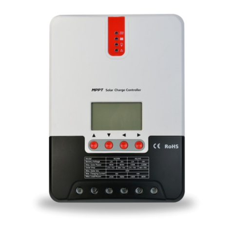
HM-CU Series Smart Solar Charge Controller
User Manual
Material Code:102868
Dear users:
Thank you very much for choosing our products!
Please read the manual carefully before using our controllers.
Version: 1.02 The above information is subject to change without prior notice.

1) As the controller will generate heat during operation, it's recommended that it be installed in an
environment with good ventilation conditions.
2) The controller will measure the ambient temperature and make compensation to battery charging based
on the measurement. As long as actual conditions permit, place the battery and the controller in the same
environment.
3) Choose cables with large enough capacity for connection, in case too much loss incurred on the lines
causes the controller to misjudge.
4) The controller has a common positive pole inside. If grounding is needed, ground the positive pole.
1) Automatic recognition of 12V/ 24V system voltages.
2) LED indicators can give a clear and intuitive indication of the operating statuses of the solar panel and
load.
3) Two USB outputs are provided with a maximum current of up to 1.2A, making it possible to charge
devices such as Iphone, Ipad, Android phones, etc. with a large current.
4) With an LCD screen cyclically displaying information including battery voltage, capacity, charging current,
discharging current, load mode, controller temperature, etc., the user can conveniently check needed
information at any time.
5) An upgraded 3-stage charging algorithm applies an equalizing charge to the battery every 30 days,
effectively preventing the battery from sulfuration, thus extending the battery's service life.
6) The load is operated with an easy-to-use manual switch.
7) A built-in temperature sensor helps to deliver high-precision temperature compensation.
8) Overcharge, over-discharge and overload protection, as well as short-circuit and reverse-polarity
protection.
9) TVS lighting protection.
1 6
127
Value
Charging or
daytime
Battery Load
Unit
Parameter
Main features
Usage Recommendations
State Indicators
Steady on
Steady on
Steady on
Steady on
Steady off
Quick flashing
Steady on
Steady off
All lighting up
Only the frame flashing
The frame and 3 dashes
all flashing
LCD icon Indicated item Status
Solar panel parameter
Battery parameter
Load discharging parameter
Daytime or charging
Night recognition
Load short-circuit or overloaded
Load turned on
Load turned off
Battery in normal state
Over-discharge
Over-voltage
12V/ 24V Auto
10A/ 20A
< 15mA
< 55V
17.0V; × 2/24V
14.6V; ×2/24V (25°C), duration: 1 hour
14.4V; ×2/24 V (25°C), duration: 2 hours
13.8V; × 2/24V (25°C)
13.2V; ×2/24V (25°C)
11.0V; × 2/24V
12.6V; × 2/24V
1.2A
-3.0mv/ °C/ 2V;
1.25 times of rated current: 30 s; short circuit: immediately.
-20°C to +50°C;
Parameter Details
System voltage
System current
No-load loss
Solar energy input voltage
Over-voltage protection
Equalizing charging voltage
Boost charging voltage
Floating charging voltage
Charging return voltage
Over-discharge voltage
Over-discharge recovery voltage
Rated total current of USB loads
Temperature compensation
Overload and short-circuit protection
Operating temperature
IP30
140g
(L×W×H) 120 × 74 × 23.6 (mm)
Protection degree
Weight
Dimensions

1) HM-CU Series controller can work under a system voltage of either 12 V or 24 V. To use it, first connect
the battery, and the controller's screen will light up and some information will be displayed. If the screen
fails to light up or display information, check whether the connection is reliable or if the battery is reversely
connected.
2) Next connect the solar panel: if sunlight is present, the solar panel indicator will light up, or else check
whether connection is correctly done.
3) Then connect the load: connect the load leads to the controller's load output terminals, and the current
shall not exceed the controller's rated current.
The wiring is shown below:
+-++
- -
Back
Solar
Panel
Battery
Load
2) The controller's installation method:
First press the controller into the mounting panel, next fit the locking bracket to the panel back and
hold the controller in place, then align the installation holes of the locking bracket to those of the
controller, and finally insert and tighten the screws. See the following diagram:
Installation Specifications
1) The controller's dimensions are as follows:
External dimensions: 120×74×23.6 (mm)
Installation dimensions: 115×70 (mm)
Installation hole diameter: 3.0 (mm)
Wiring
One way
Another way
Controller
Controller
Set Screws
Wall
Classis Panel
Set Screws

1) After the controller is installed and enters into normal operation (the battery indicator keeps steady on),
a tap on the key will turn on or off the load.
2) When the load is overloaded or short circuited, disconnect the load and make sure the load is
compatible with the controller before reconnecting it; a short circuit can be either automatically
deactivated at a set time or manually deactivated. In the manual mode, tap the load key to release the load
from the protection status and shut it off, and another tap on the load key will turn on the load again.
3) When the system is experiencing over-voltage or over-discharge, the load will be forcefully shut down.
When the system voltage recovers, the load will be released from its protection status and restored to
normal operation.
4) The load is in the manual mode by default. In either mode, long press the key to enter into the mode
setting interface in which the load mode begins to flash, tap the key to change the mode, and after setting
is finished, long press the key to save the setting and exit, or you can also wait for 10 seconds to have the
saving and exiting process automatically done.
1) Pure light control (0): when sunlight disappears and the light intensity drops to the starting point (light
control off), the controller first initiates a 1-minute delay to confirm the starting signal, and then switches
on the load for operation according to parameter settings; when sunlight emerges and the light intensity
reaches the starting point, the controller first initiates a 1-minute delay to confirm the shutting-down
signal, and then shut down the output to stop the load's operation.
2) Light control + time control (1 to 14): the starting process is the same as the sole light control, and
after operating for a preset period of time (settable from 1 to 14 hours), the load turns off automatically.
3) Manual mode (15): in this mode, the user can switch the load on or off by the key, no matter whether
it's day or night.
4) Debugging mode (16): 6V (settable) with light signals, the load is shut off; 5V (varies according to the
preset light controlled voltage and system voltage) without light signals, the load is switched on. This
mode enables fast check of the correctness of system installation during installation debugging.
5. Normal on (17): the energized load keeps outputting.
Overload and short-circuit automatic recovery time: 1st time, 5 s; 2nd time, 10 s; 3rd time, 25 s; 4th time, 30
s; 5th time, manual recovery or automatic recovery the next day.
Operating Method
Load Mode
Mode
Sole light control mode
Light control + time control (1 to 14 hours)
Manual mode (factory default)
Debugging mode
Normal on mode
Display
00
01-14
15
16
17
Load Overload, Short-Circuit and Recovery
Corresponding error
No error
Battery over-discharge
Battery over-voltage
Load short circuit
Load overloaded
Temperature too high inside controller
Error Code List
Code on LCD screen
E0
E1
E2
E4
E5
E6
Causes and solutions
Check whether the battery is correctly connected.
Check whether the ambient temperature is too low
and whether the display will recover when the temperature
rises.
Check whether the solar panel is correctly connected and
contact is good and reliable; check whether the solar panel
voltage falls below the battery voltage.
System over-voltage, check whether the battery voltage is
too high.
The battery is over-discharged, and will recover when
recharged adequately.
The load's power exceeds the rated value or it's short-circuited.
After removing the problem, long press the key or wait until it
recovers automatically.
Check whether wiring is sound and reliable and system voltage
is correctly recognized.
Common Problems and Solutions
Symptoms
LCD screen won't light up
Incomplete display or no renewal on
LCD screen
While sunlight is present, the solar
panel icon won't light up
The battery icon flashes quickly, and
no output
The battery icon flashes slowly, and
no output
The load icon flashes quickly, and
no output
Other symptoms
This manual suits for next models
1
Other Srne Controllers manuals
Popular Controllers manuals by other brands
SOMFY
SOMFY Animeo Motor Controller 6 AC IB+ DRM installation guide

Western
Western Wmarine10 user manual
Autoscript
Autoscript FC/WIRELESS-IP Operation manual
SMC Corporation
SMC Corporation LEC-BCW Series Operation manual
Malmbergs
Malmbergs EFP700DC instruction manual

Oase
Oase Eco Control operating instructions
