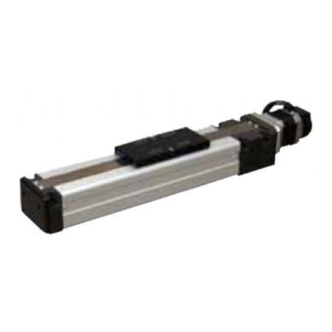
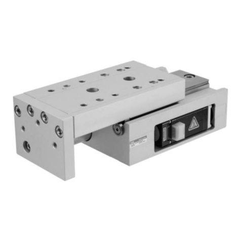
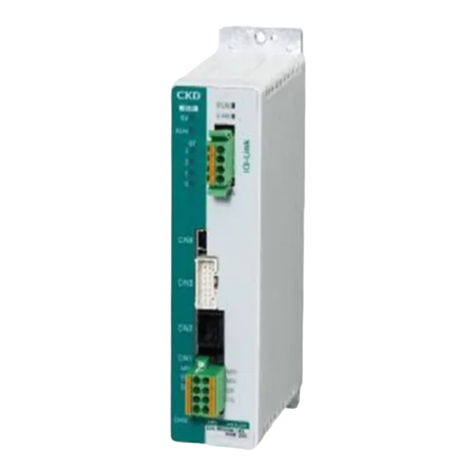
CKD ERL2 Series User manual

( 器 ) 世界モ (16.11.8)B-44.ai
CKDINDIAPRIVATELTD.
CKDINDIAPRIVATELTD.BANGALOREBRANCH
TAIWANCKDCORPORATION
CKDUKOFFICE
CKDCZECHOFFICE CKDSINGAPOREPTE.LTD.
CKDCORPORATIONBRANCHOFFICE
M-CKDPRECISIONSDN.BHD.
CKDTHAICORPORATIONLTD.
:Distributors
CKDUSACORPORATION
CKDKOREACORPORATION
CKD(SHANGHAI)CORPORATION
PTCKDTRADINGINDONESIA
CKDFRANKFURT
OFFICE
CKDVIETNAM
ENGINEERINGCO.,LTD
CKDMEXICO,S.DER.L.DEC.V.
CKDEUROPEB.V.
CKDEUROPEBRANCH
●Specifications are subject to change without notice.
The goods and/or their replicas, the technology and/or software found in this catalog are subject to complementary export
regulations by Foreign Exchange and Foreign Trade Law of Japan.
If the goods and/or their replicas, the technology and/or software found in this catalog are to be exported, law requires that the
exporter makes sure that they will never be used for the development and/or manufacture of weapons for mass destruction.
2017.08
CKD Corporation 2017 All copy rights reserved.
U.S.A.
CKDUSACORPORATION
●CHICAGOHEADQUARTERS
4080 Winnetka Avenue, Rolling Meadows, IL 60008, USA
PHONE +1-847-368-0539 FAX +1-847-788-0575
・CINCINNATIOFFICE
・SANANTONIOOFFICE
・SANJOSEOFFICE
・DETROITOFFICE
Mexico
CKDMEXICO,S.DER.L.DEC.V.
Cerrada la Noria No. 200 Int. A-01, Querétaro Park II,
Parque Industrial Querétaro, Santa Rosa Jáuregui,
Querétaro, C.P. 76220, México
PHONE +52-442-161-0624
Europe
CKDEUROPEB.V.
Beechavenue 125A, 1119 RB Schiphol-Rijk, The Netherlands
PHONE +31-23-554-1490
CKDCORPORATIONEUROPEBRANCH
Beechavenue 125A, 1119 RB Schiphol-Rijk, The Netherlands
PHONE +31-23-554-1490
・CZECHOFFICE
・UKOFFICE
・FRANKFURTOFFICE
Malaysia
M-CKDPRECISIONSDN.BHD.
●HEADOFFICE
Lot No.6,Jalan Modal 23/2, Seksyen 23, Kawasan MIEL,
Fasa 8, 40300 Shah Alam,Selangor Darul Ehsan, Malaysia
PHONE +60-(0)3-5541-1468 FAX +60-(0)3-5541-1533
・JOHORBAHRUBRANCHOFFICE
・PENANGBRANCHOFFICE
Thailand
CKDTHAICORPORATIONLTD.
●SALESHEADQUARTERS
Suwan Tower, 14/1 Soi Saladaeng 1, North Sathorn Road,
Kwaeng Silom, Khet Bangrak, Bangkok 10500, Thailand
PHONE +66-(0)2-267-6300 FAX +66-(0)2-267-6305
・RAYONGOFFICE
・NAVANAKORNOFFICE
・EASTERNSEABOARDOFFICE
・LAMPHUNOFFICE
・KORATOFFICE
・AMATANAKORNOFFICE
・PRACHINBURIOFFICE
・SARABURIOFFICE
Singapore
CKDSINGAPOREPTE.LTD.
No.33 Tannery Lane #04-01 Hoesteel Industrial
Building, Singapore 347789, Singapore
PHONE +65-67442623 FAX +65-67442486
CKDCORPORATIONBRANCHOFFICE
No.33 Tannery Lane #04-01 Hoesteel Industrial
Building, Singapore 347789, Singapore
PHONE +65-67447260 FAX +65-68421022
India
CKDINDIAPRIVATELTD.
Unit No. 607, 6th Floor, Welldone Tech Park, Sector 48,
Sohna Road, Gurgaon-122018, Haryana, India
PHONE +91-(0)124-418-8212
CKDINDIAPRIVATELTD.BANGALOREBRANCH
No. 201/B, 2nd Floor, Museum Terraces Apartment, No. 29,
Museum Road, Bangalore-560001, Karnataka, India
PHONE +91-(0)80-4212-7008/7009 FAX +91-(0)80-4212-7007
Indonesia
PTCKDTRADINGINDONESIA
Menara Bidakara 2, 18th Floor, Jl. Jend. Gatot Subroto Kav.
71-73, Pancoran, Jakarta 12870, Indonesia
PHONE +62 21-2938-6601 FAX +62 21-2906-9470
Vietnam
CKDVIETNAMENGINEERINGCO.,LTD.
18th Floor, CMC Tower, Duy Tan Street, Cau Giay
District, Hanoi, Vietnam
PHONE +84-4-37957631 FAX +84-4-37957637
Taiwan
台湾喜開理股 有限公司
TAIWANCKDCORPORATION
16F-3, No. 7, Sec. 3, New Taipei Blvd., Xinzhuang Dist.,
New Taipei City 242, Taiwan
PHONE +886-(0)2-8522-8198 FAX +886-(0)2-8522-8128
・新竹営業所(HSINCHUOFFICE)
・台中営業所(TAICHUNGOFFICE)
・台南営業所(TAINANOFFICE)
China
喜開理(上海)機器有限公司
CKD(SHANGHAI)CORPORATION
●
営業部 / 上海浦西事務所(SALESHEADQUARTERS/SHANGHAIPUXIOFFICE)
Room 601, 6th Floor, Yuanzhongkeyan Building, No. 1905
Hongmei Road, Xinhui District, Shanghai 200233, China
PHONE +86-(0)21-61911888 FAX +86-(0)21-60905356
・
上海浦東事務所(SHANGHAIPUDONGOFFICE)
・無錫事務所(WUXIOFFICE)
・杭州事務所(HANGZHOUOFFICE)
・寧波事務所(NINGBOOFFICE)
・南京事務所(NANJINGOFFICE)
・蘇州事務所(SUZHOUOFFICE)
・昆山事務所(KUNSHANOFFICE)
・北京事務所(BEIJINGOFFICE)
・天津事務所(TIANJINOFFICE)
・長春事務所(CHANGCHUNOFFICE)
・大連事務所(DALIANOFFICE)
・青島事務所(QINGDAOOFFICE)
・済南事務所(JINANOFFICE)
・烟台事務所(YANTAIOFFICE)
・瀋陽事務所(SHENYANGOFFICE)
・重慶事務所(CHONGQINGOFFICE)
・成都事務所(CHENGDUOFFICE)
・西安事務所(XIANOFFICE)
・武漢事務所(WUHANOFFICE)
・鄭州事務所(ZHENGZHOUOFFICE)
・長沙事務所(CHANGSHAOFFICE)
・広州事務所(GUANGZHOUOFFICE)
・深圳西事務所(WESTSHENZHENOFFICE)
・深圳東事務所(EASTSHENZHENOFFICE)
・東莞事務所(DONGGUANOFFICE)
・厦門事務所(XIAMENOFFICE)
Korea
CKDKOREACORPORATION
●HEADQUARTERS
(3rd Floor), 44, Sinsu-ro, Mapo-gu, Seoul 121-856, Korea
PHONE +82-
(
0
)
2-783-5201〜5203 FAX +82-
(
0
)
2-783-5204
・水原営業所(SUWONOFFICE)
・天安営業所(CHEONANOFFICE)
・蔚山営業所(ULSANOFFICE)
□2-250,Ouji,KomakiCity,Aichi,Japan485-8551
□PHONE+81-(0)568-74-1338FAX+81-(0)568-77-3461
Websitehttp://www.ckd.co.jp/
Space-saving installation
Flexible motor mounting

compatible!!
Pulse train
input
compatible
Automatic actuator recognition
Addition of new controller
compatible with pulse trains
Enables current position confirmation
with position output
Allows 63 multi-point positioning
Smallest controller class in the
industry
With the adoption of “ballscrew with lubrication
equipment” and “liner guide with ball
retainer”, long-term
maintenance-free operation
is provided
Electric Slider Actuator
Electric Rod Actuator
Flexible motor mounting
Space savings from various motor
mountings to fit your equipment
In addition to the conventional straight
type, a selection of right-hand, left-hand
and bottom are available
Right-hand Left-hand Bottom
With the Handy Terminal, setting the PC
software "E Tools" has never been easier
Simple operation with
Handy Terminal
Easy, even for
beginners

System conguration
Setting tools
The areas indicated by the thin lines should be prepared by the customer.
Basic setting items Basic driving methods
1. Set the necessary parameters from a PC or handy
terminal
2. Set the point data in a similar manner
1. Input a destination point signal from a PLC
2. Input a start signal from a PLC
3.
After it is driving, output a “positioning complete” signal from the controller
Name Quantity
Standard conguration
Actuator unit 1
Controller unit 1
I/O Cable 1
Motor encoder relay cable 1
Conguration (When selecting the set model No.)
Part used Model No. Manufacturer
Surge protector
R/A/V-781BXZ-4
R/A/V-781BWZ-4
RSPD-250-Q4
RSPD-250-U4
OKAYA ELECTRIC
INDUSTRIES CO.,
LTD.
A surge protector is required to comply with the CE marking. Refer
to the Instruction Manual for details about installation and wiring.
We offer the "ETP2" handy terminal.
We offer the "E Tools" electric actuator setting software.
(Windows version provided free of charge)
You can set the point data and parameters for the ERL2/ESD2
electric actuators and issue operation instructions from a PC.
The point data and parameter data can be saved to the PC.
An RS-485 interface and a PC communication cable
(EC-CBLPC1) are required for a PC connection.
Recommended RS-485 interface model numbers
MISUMI PCCM-COM-1PDUSBH-R
CONTEC COM-1PD (USB) H
Note 1: Because the PC communication cable is designed
specically for CKD's electric actuator, commercially
available communication cables cannot be used.
Accidentally using the wrong cable may damage the
controller and PC.
Note 2: The handy terminal and PC are expected to only be
connected when making adjustments. Remove the cable
from the controller during normal operation.
Note 3: The PC may be unable to recognize the RS485 interface
when recovering from sleep mode, and communication
anomalies may occur.
Actuator
ERL2 Series
Refer to pages 1 to 11
Actuator
ESD2 Series
Refer to pages 13 to 27
PLC
Handy terminal
ETP2
Refer to pages 39 to 40
(Sold separately)
PC communication cable (sold separately)
EC-CBLPC1
Refer to page 41
PC
Motor encoder relay cable
(Fixed, movable) Refer to page 42
I/O Cable
Refer to page 42
Controlle
EC07/EC63/ECPT
Refer to pages 29 to 38
24 VDC
power supply
Power supply
Noise lter
(Sold separately)
Refer to page 41
Ground
Ground
Surge protector
(Sold separately)
Refer to page 41
RS485 interface
Ground Ground
Ground
Intro 1

"E Tools" electric actuator setting software
Note: An RS-485 interface and a separate PC communication cable (page 41) are required to connect the PC and
controller.
Download the "E Tools" electric actuator setting software and the Instruction Manual from the CKD website.
Website address: http://www.ckd.co.jp
Operation instructions
You can perform the following manual operations from E Tools
Jog
Inching
Point movement
Forced output to the general purpose output
You can easily set multiple point data settings.
Monitor
Actuator operational status
Input and output status of the general purpose input and
output
Check the alarm history stored on the controller
Settings
Easy editing and setting of point data and parameters
Main functions
Intro 2

Selection guide
Type
Model No. Stroke (mm)
Max. load capacity (kg)
Lead
(mm)
Max.
pressing
force
(N)
Max.
speed
(mm/s)
Listed
page
50 100 150 200 250 300 350 400 450 500 550 600 700 800 10 20 30 40 50 60 70 80
Slider
ERL2-45E06
ERL2-45R06
ERL2-45L06 510 6220
(*1) 300
1
ERL2-45D06
ERL2-45E12
ERL2-45R12
ERL2-45L12 2512 110
(*1) 600
ERL2-45D12
ERL2-60E06
ERL2-60R06
ERL2-60L06 30 6640
(*1) 200
1
ERL2-60D06
ERL2-60E12
ERL2-60R12
ERL2-60L12 1 16 12 320
(*1) 400
ERL2-60D12
Rod
ESD2-35E06
33 6220 300
13
ESD2-35R06
ESD2-35L06
ESD2-35D06
ESD2-35E12
416 12 110 600
ESD2-35R12
ESD2-35L12
ESD2-35D12
ESD2-45E06
33 6220 300
13
ESD2-45R06
ESD2-45L06
ESD2-45D06
ESD2-45E12
416 12 110 600
ESD2-45R12
ESD2-45L12
ESD2-45D12
ESD2-55E06
67 6640 200
13
ESD2-55R06
ESD2-55L06
ESD2-55D06
ESD2-55E12
34 12 320 400
ESD2-55R12
ESD2-55L12
ESD2-55D12
*1: Use within the allowable moment.
*2: The values for the rod horizontal load capacity are based on an actuator used in combination with an external guide.
Intro 3

Selection guide
Type
Model No. Stroke (mm)
Max. load capacity (kg)
Lead
(mm)
Max.
pressing
force
(N)
Max.
speed
(mm/s)
Listed
page
50 100 150 200 250 300 350 400 450 500 550 600 700 800 10 20 30 40 50 60 70 80
Slider
ERL2-45E06
ERL2-45R06
ERL2-45L06 510 6220
(*1) 300
1
ERL2-45D06
ERL2-45E12
ERL2-45R12
ERL2-45L12 2512 110
(*1) 600
ERL2-45D12
ERL2-60E06
ERL2-60R06
ERL2-60L06 30 6640
(*1) 200
1
ERL2-60D06
ERL2-60E12
ERL2-60R12
ERL2-60L12 1 16 12 320
(*1) 400
ERL2-60D12
Rod
ESD2-35E06
33 6220 300
13
ESD2-35R06
ESD2-35L06
ESD2-35D06
ESD2-35E12
416 12 110 600
ESD2-35R12
ESD2-35L12
ESD2-35D12
ESD2-45E06
33 6220 300
13
ESD2-45R06
ESD2-45L06
ESD2-45D06
ESD2-45E12
416 12 110 600
ESD2-45R12
ESD2-45L12
ESD2-45D12
ESD2-55E06
67 6640 200
13
ESD2-55R06
ESD2-55L06
ESD2-55D06
ESD2-55E12
34 12 320 400
ESD2-55R12
ESD2-55L12
ESD2-55D12
*1: Use within the allowable moment.
*2: The values for the rod horizontal load capacity are based on an actuator used in combination with an external guide.
11
6.5
6.5
10
10
15
(*2)
(*2)
(*2)
(*2)
(*2)
(*2)
Horizontal
Vertical
Intro 4

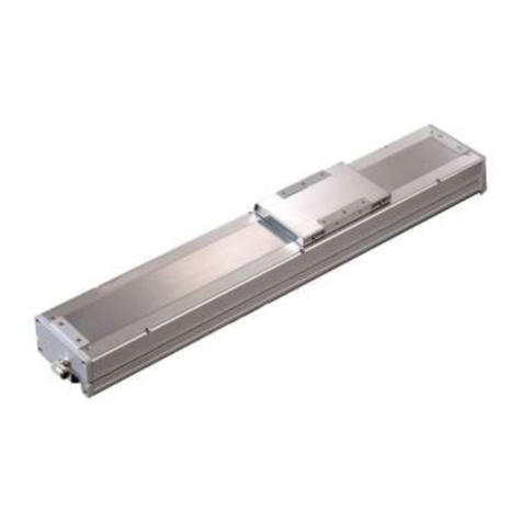
Electric actuator Slider
ERL2 Series
Compatibility function allows the controller, actuator, and cable to be
freely combined
The electric actuator that works like a pneumatic cylinder
Motor sizes: 42 / 56
Actuator specications
*1: The maximum load capacity decreases when the speed increases. For more details, refer to the vertical and horizontal load capacity charts and graphs in the
next page.
*2: Use within the allowable moment. (Refer to page 46 for the allowable moment value.)
Descriptions ERL2-45 ERL2-60
Actuator Slider
Motor Stepping motor
Encoder Incremental
Drive system Rolling ball screw
Outer diameter 8 mm
Rolling ball screw
Outer diameter 12 mm
Motor size mm 42 56
Screw lead mm 6 12 6 12
Stroke mm
50, 100, 150, 200
250, 300, 350, 400
450, 500
50, 100, 150, 200
250, 300, 350, 400
450, 500, 550, 600
700
Operation speed range mm/s 15 to 300 30 to 600 15 to 200 30 to 400
Operation acceleration/deceleration speed range
m/s21.0 to 3.0
Repeatability mm ±0.02
Lost motion mm 0.1 or less
Max. load capacity
*1
Horizontal kg 10 5 30 16
Vertical kg 5 2 11 6.5
Maximum pressing force *2 N 220 110 640 320
Motor power supply voltage 24 VDC±10%
Motor section maximum instantaneous current
A 2.7 4
Brake
Type Non-excitation operation
Power supply voltage
24 VDC±10%
Power consumption
W 6.1 7.2
Holding force N 140 70 610 305
Insulation resistance 10 MΩ or higher 500 VDC
Withstand voltage 500 VAC for 1 minute
Operating ambient temperature 0 to 40°C (no freezing)
Operating ambient humidity 35 to 80% RH (no condensation)
Storage ambient temperature -10 to 50°C (no freezing)
Storage ambient humidity 35 to 80% RH (no condensation)
Atmosphere No corrosive gas, explosive gas, or dust
Degree of protection IP4X
Weight
Body size
Motor
Mounting direction
50 st 100 st 150 st 200 st 250 st 300 st 350 st 400 st 450 st 500 st 550 st 600 st 700 st
ERL2-45
E1.5
(1.8)
1.6
(1.9)
1.7
(2.0)
1.8
(2.1)
1.9
(2.2)
2.0
(2.3)
2.1
(2.4)
2.2
(2.5)
2.3
(2.6)
2.5
(2.8) ―――
R/L/D 1.7
(2.0)
1.8
(2.1)
1.9
(2.2)
2.0
(2.3)
2.1
(2.4)
2.2
(2.5)
2.3
(2.6)
2.4
(2.7)
2.5
(2.8)
2.7
(3.0)
ERL2-60
E3.2
(3.8)
3.4
(4.0)
3.6
(4.2)
3.8
(4.4)
4.0
(4.6)
4.2
(4.8)
4.4
(5.0)
4.6
(5.2)
4.8
(5.4)
5.0
(5.6)
5.2
(5.8)
5.4
(6.0)
5.8
(6.4)
R/L/D 3.7
(4.3)
3.9
(4.5)
4.1
(4.7)
4.3
(4.9)
4.5
(5.1)
4.7
(5.3)
4.9
(5.5)
5.1
(5.7)
5.3
(5.9)
5.5
(6.1)
5.7
(6.3)
5.9
(6.5)
6.3
(6.9)
Note: the numbers in ( ) indicate the product weight with the brake
(kg)
1

ERL2 Series
Vertical load capacity, horizontal load capacity, pressing force
Vertical load capacity
ERL2-45 ERL2-60
Horizontal load capacity
ERL2-45 ERL2-60
Pressing force
ERL2-45 ERL2-60
8
10
12
6
4
2
0
0100 200 300 400 500
Speed (mm/s)
Lead 12
Lead 6
Speed (mm/s)
800
600400200
0
0
1
2
3
4
5
6
Lead 6
Lead 12
Load capacity (kg)Load capacity (kg)
35
20
25
30
15
10
5
0
0100 200 300 400 500
Speed (mm/s)
Lead 12
Lead 6
Speed (mm/s)
800
600400200
0
0
2
4
6
8
10
12
Lead 6
Lead 12
250
100
150
200
50
0
020 40 60 80 100
Pressing current set value (%)
Note: Use within the allowable moment.
Pressing force (N)
Lead 12
Lead 6
400
500
600
700
300
200
100
0
0 20 40 60 80 100
Note: Use within the allowable moment.
Pressing current set value (%)
Lead 12
Lead 6
Pressing force (N)
2

ERL2 Series
HController
I
I/O Cable length
G
Relay cable length
DStroke
CScrew lead
ERL2
How to order
Model No.
BMotor mounting direction
ABody size
Code Content
Body size
45 Body size 45
60 Body size 60
Motor mounting direction
EStandard mounting (straight)
RRight-hand mounting
LLeft-hand mounting
DBottom mounting
Screw lead
06 6 mm
12 12 mm
Stroke
Code Length Body size/Motor mounting direction
45E/45R/45L 45D
60E/60R/60L
60D
05 50 mm
10 100 mm
15 150 mm
20 200 mm
25 250 mm
30 300 mm
35 350 mm
40 400 mm
45 450 mm
50 500 mm
55 550 mm
60 600 mm
70 700 mm
Brake
NWithout brake
BWith brake
Origin position
MMotor side
FOpposite side of the motor
Relay cable length
N0 None
S1 Fixing cable 1 m
S3 Fixing cable 3 m
S5 Fixing cable 5 m
SX Fixing cable 10 m
R1 Movable cable 1 m
R3 Movable cable 3 m
R5 Movable cable 5 m
RX Movable cable 10 m
Controller
NNone *1
AEC07 standard mounting
BEC07 DIN rail mount
CEC63 standard mounting
DEC63 DIN rail mount
EECPT standard mounting *2
FECPT DIN rail mount *2
I/O Cable length
NNone
22 m
33 m *3
55 m *3
A
B
C
D
E
G
F
H
I
60 E 06 50 MB RX B 2
ERL2-60E06-50BM-RXB2
A Body size : 60
B
Motor mounting direction
:
standard mounting (straight)
C Screw lead : 6 mm
D Stroke : 500 mm
E Brake : with brake
F Origin position : motor side
G
Relay cable length
: movable cable 10 m
H Controller : EC07 DIN mounting rail
I I/O Cable length : 2 m
[Example of model No.]
*1: When H controller is set to "N", also
select "N" for I
I/O cable.
*2: Use a PLC unit which meets the ECPT pulse train signal input
specications (refer to page 34).
*3: If the code for the controller is E or F, these cables can be used only
when the differential system is used as the pulse train signal system.
Only a cable length of 2 m can be used with the open collector
system.
* For details, refer to "How to order" on page 29.
Controller individual model No.
Series
Mounting method
EC 07 B
*Refer to page 42 for details.
Cable discrete model No.
Relay cable
EC CBLME1
Fixed/movable
Cable length
S 5
I/O Cable
Controller Series
Cable length
EC CBLIF1 07 5
Set model No. (actuator, controller, cable)
N0 N N
Body size
Motor mounting direction
Actuator body discrete model No.
A
B
Screw lead
C
Origin position
F
ERL2
Stroke
D
60 E 06 50 MB
Brake
E
FOrigin position
EBrake
3

Dimensions
ERL2-45E (standard mounting straight)
Stroke Code 05 10 15 20 25 30 35 40 45 50
X (mm) 50 100 150 200 250 300 350 400 450 500
Total length L
(mm)
Without brake
313 363 413 463 513 563 613 663 713 763
With brake 353 403 453 503 553 603 653 703 753 803
Body length LL (mm) 206 256 306 356 406 456 506 556 606 656
L3 (mm) 151 201 251 301 351 401 451 501 551 601
L4 (mm) 141.6 191.6 241.6 291.6 341.6 391.6 441.6 491.6 541.6 591.6
Number of mounting holes P 4 6 6 8 8 10 10 12 12 14
Number of mounting hole intervals
N1223344556
Weight (kg)
Without brake
1.5 1.6 1.7 1.8 1.9 2.0 2.1 2.2 2.3 2.5
With brake 1.8 1.9 2.0 2.1 2.2 2.3 2.4 2.5 2.6 2.8
Note 1: Operating range during origin return
Note 2: The numbers within the [ ] are the dimensions with the brake
ERL2 Series
How to order/Dimensions
48
56.5
44
9
15±0.05
30
38
81
20
26
28±0.05
32
42
6.5
10
4.5
36
12
10
29
L3
36
23
2-Long through hole 4-M4 depth 7.5
4-φ 3H7 depth 7.5
4-4.5 THRU
Stroke length: X 40.5 55.5
9
14
19 N × 100
P-M4 depth 8
4-M2.6 depth 3.5
16.9 L4
15
14
Body length: LL
13.5 [53.5] Note 2
93.5
Ground terminal
M3 depth 6
3.5
Total length: L
45
25
45
59.5
25
42
9.5
(8) Note 1
(8) Note 1
4.5
0.8 0.8
(300)
Connect to relay cable
Fixing cable allowable
bending R50
(20)
(49)
23
4

Dimensions
ERL2-45R (right-hand mounting)
Stroke Code 05 10 15 20 25 30 35 40 45 50
X (mm) 50 100 150 200 250 300 350 400 450 500
Total length L (mm) 236 286 336 386 436 486 536 586 636 686
Body length LL (mm) 206 256 306 356 406 456 506 556 606 656
L3 (mm) 151 201 251 301 351 401 451 501 551 601
Number of mounting holes P 4 6 6 8 8 10 10 12 12 14
Number of mounting hole intervals
N1223344556
Weight (kg)
Without brake
1.7 1.8 1.9 2.0 2.1 2.2 2.3 2.4 2.5 2.7
With brake 2.0 2.1 2.2 2.3 2.4 2.5 2.6 2.7 2.8 3.0
Note 1: Operating range during origin return
Note 2: The numbers within the [ ] are the dimensions with the brake
Note 3: Be sure to also mount and use the xing tap for the slider bottom when using the xing tap for the slider edge.
ERL2 Series
(8) Note 1
Stroke: X
Total length: L
45.5
33
Body length: LL
15±0.05
4-φ4.5 through
(107 to 109)
95.5
16
4-M4 depth 10
(Fixing tap for
the slider edge)
Note 3
2-through slot
364.5
32
26
20
28±0.05
49.8
45
42
56.5
0.8 48 0.8
4-M4 depth 7.5
4-φ3H7 depth 7.5
(20)
(300)
(49) Connect to the relay cable
Fixing cable
Allowable bend R50
Grounding terminal M3 depth 6
N × 100
14
19
29.5
4
A View
A
93.5
17 [57] Note 2
30
45
25
6.5
81
38
30
9
L3 29
12
40.5 55.5
(8) Note 1
P-M4 depth 8
(Fixing tap for the slider bottom)
Note 3
5

Dimensions
ERL2-45L (left-hand mounting)
Stroke Code 05 10 15 20 25 30 35 40 45 50
X (mm) 50 100 150 200 250 300 350 400 450 500
Total length L (mm) 236 286 336 386 436 486 536 586 636 686
Body length LL (mm) 206 256 306 356 406 456 506 556 606 656
L3 (mm) 151 201 251 301 351 401 451 501 551 601
Number of mounting holes P 4 6 6 8 8 10 10 12 12 14
Number of mounting hole intervals
N1223344556
Weight (kg)
Without brake
1.7 1.8 1.9 2.0 2.1 2.2 2.3 2.4 2.5 2.7
With brake 2.0 2.1 2.2 2.3 2.4 2.5 2.6 2.7 2.8 3.0
Note 1: Operating range during origin return
Note 2: The numbers within the [ ] are the dimensions with the brake
Note 3: Be sure to also mount and use the xing tap for the slider bottom when using the xing tap for the slider edge.
ERL2 Series
Dimensions
19 N × 100
P-M4 depth 8
(Fixing tap for the slider bottom)
Note 3
(20)
(49)
Connect to the relay cable
A View
48
0.8 0.8
25
45
49.8
4
93.5
4-φ3H7 depth 7.5
4-M4 depth 7.5
17 [57] Note 2
30
4-φ4.5 through 33
45.5
9
15±0.05
30
38
12
6.5
2-through slot
Body length: LL
L3
81
29
Total length: L
Grounding terminal M3 depth 6
Fixing cable
Allowable bend R50
14
56.5
(300)
4.5
32
26
20
28±0.05
36
20.5
42
45
(107 to 109)
16
95.5
A
(8) Note 1
(8) Note 1
Stroke: X 40.5 55.5
4-M4 depth 10
(Slider edge
xing tap)
Note 3
6

ERL2
Series
Dimensions
ERL2-45D (bottom mounting)
Stroke Code 05 10 15 20 25 30 35 40 45 50
X (mm) 50 100 150 200 250 300 350 400 450 500
Total length L (mm) ― ― 336 386 436 486 536 586 636 686
Body length LL (mm) ― ― 306 356 406 456 506 556 606 656
Number of mounting holes P ― ― 4 4 6 6 8 8 10 10
Number of mounting hole intervals
N― ― 11223344
Weight (kg)
Without brake
― ― 1.9 2.0 2.1 2.2 2.3 2.4 2.5 2.7
With brake ― ― 2.2 2.3 2.4 2.5 2.6 2.7 2.8 3.0
Note 1: Operating range during origin return
Note 2: The numbers within the [ ] are the dimensions with the brake
Note 3: Be sure to also mount and use the xing tap for the slider bottom when using the xing tap for the slider edge.
Total length: L
12
Body length: LL
81
38
30
4.5
32
26
20
28±0.05
36
20
42
56.5
14
(300)
25 16
95.5
45
15±0.05
4-M4 depth 7.5 4-φ3H7 depth 7.5
9
6.5
2-through slot
45 (8) Note 1
Stroke: X 40.5
(8) Note 1
93.5
17 [57] Note 2
(49)
A
Connect to the relay cable
N × 100 4
19
Grounding terminal
M3 depth 6
Fixing cable
Allowable bend R50
30
55.5
45 4-M4 depth 10
(Slider edge
xing tap)
Note 3
33
0.8 0.8
A View
(20)
48
P-M4 depth 8
(Fixing tap for the slider bottom)
Note 3
7

Dimensions
ERL2-60E (standard mounting straight)
Stroke Code 05 10 15 20 25 30 35 40 45 50 55 60 70
X (mm) 50 100 150 200 250 300 350 400 450 500 550 600 700
Total length L
(mm)
Without brake
367 417 467 517 567 617 667 717 767 817 867 917 1017
With brake 409 459 509 559 609 659 709 759 809 859 909 959 1059
Body length LL (mm) 237 287 337 387 437 487 537 587 637 687 737 787 887
L3 (mm) 171 221 271 321 371 421 471 521 571 621 671 721 821
L4 (mm) 171 221 271 321 371 421 471 521 571 621 671 721 821
Number of mounting holes P 4 6 6 8 8 10 10 12 12 14 14 16 18
Number of mounting hole intervals
N1223344556678
Weight (kg)
Without brake
3.2 3.4 3.6 3.8 4.0 4.2 4.4 4.6 4.8 5.0 5.2 5.4 5.8
With brake 3.8 4.0 4.2 4.4 4.6 4.8 5.0 5.2 5.4 5.6 5.8 6.0 6.4
Note 1: Operating range during origin return
Note 2: The numbers within the [ ] are the dimensions with the brake
ERL2 Series
Dimensions
Ground terminal
M3 depth 6
21
50
60
110
23
31
39
50
7.5
12
5.5
12
52
12
35
52
L314
4-M5 depth 10
2-Long through hole
4-4.5 THRU
Stroke length: X 55 56
L4 4
Body length: LL
13 [55] Note 2
117
Total length: L
64
32
60
74.5
71.5
60
14
35
34±0.05
30
4-M2.6 depth 3
31±0.05 (φ 3 Dimensions)
4-φ3H7 depth 10
25
P-M5 depth 9
33 N×100
50
6
64 0.80.8
(8) Note 1
(8) Note 1
23
9
(300)
Connect to relay cable
23
(20)
(49)
16
Fixing cable
allowable
bending R50
8

Dimensions
ERL2-60R (right-hand mounting)
Note 1: Operating range during origin return
Note 2: The numbers within the [ ] are the dimensions with the brake
Note 3: Be sure to also mount and use the xing tap for the slider bottom when using the xing tap for the slider edge.
Stroke Code 05 10 15 20 25 30 35 40 45 50 55 60 70
X (mm) 50 100 150 200 250 300 350 400 450 500 550 600 700
Total length L (mm)
267 317 367 417 467 517 567 617 667 717 767 817 917
Body length LL (mm) 237 287 337 387 437 487 537 587 637 687 737 787 887
L3 (mm) 171 221 271 321 371 421 471 521 571 621 671 721 821
Number of mounting holes P 4 6 6 8 8 10 10 12 12 14 14 16 18
Number of mounting hole intervals
N1223344556678
Weight (kg)
Without brake
3.7 3.9 4.1 4.3 4.5 4.7 4.9 5.1 5.3 5.5 5.7 5.9 6.3
With brake 4.3 4.5 4.7 4.9 5.1 5.3 5.5 5.7 5.9 6.1 6.3 6.5 6.9
ERL2
Series
Stroke: X
64
71.5
64
0.8 0.8
50
66.8
32
60
Total length: L
Body length: LL
4-φ5.5 through
(140.5 to 142.5)
125
16
60
43
4-M5 depth 12
(Fixing tap for the slider edge)
Note 3
110
60
21
50
34±0.05
2-through slot
4-M5 depth 10
31±0.05
4-φ3H7 depth 10
Grounding terminal
M3 depth 6
Fixing cable
Allowable bend R50
Connect to the relay cable
N × 100
25
33
(49)
A
(300)
(20)
A View
4
27
117
19 [61] Note 2
30
52 6
7.5
39
23
L3 35
14
55 56
(8) Note 1
(8) Note 1
P-M5 depth 9
(Fixing tap for the slider bottom)
Note 3
9

Dimensions
ERL2-60L (left-hand mounting)
Note 1: Operating range during origin return
Note 2: The numbers within the [ ] are the dimensions with the brake
Note 3: Be sure to also mount and use the xing tap for the slider bottom when using the xing tap for the slider edge.
Stroke Code 05 10 15 20 25 30 35 40 45 50 55 60 70
X (mm) 50 100 150 200 250 300 350 400 450 500 550 600 700
Total length L (mm)
267 317 367 417 467 517 567 617 667 717 767 817 917
Body length LL (mm) 237 287 337 387 437 487 537 587 637 687 737 787 887
L3 (mm) 171 221 271 321 371 421 471 521 571 621 671 721 821
Number of mounting holes P 4 6 6 8 8 10 10 12 12 14 14 16 18
Number of mounting hole intervals
N1223344556678
Weight (kg)
Without brake
3.7 3.9 4.1 4.3 4.5 4.7 4.9 5.1 5.3 5.5 5.7 5.9 6.3
With brake 4.3 4.5 4.7 4.9 5.1 5.3 5.5 5.7 5.9 6.1 6.3 6.5 6.9
ERL2 Series
Dimensions
(20)
Connect to the relay cable
Grounding terminal
M3 depth 6
(140.5 to 142.5)
125
16
4
27
Fixing cable
Allowable bend R50
2-through slot
34±0.05
4-M5 depth 10
4-φ3H7 depth 10
Body length: LL
4-φ5.5 through 4-M5 depth 12
(Slider edge
xing tap)
Note 3
43
60
Total length: L
(8) Note 1
(8) Note 1
Stroke: X
N × 100
P-M5 depth 9
(Fixing tap for the slider bottom)
Note 3
25
33
55 56
L3 35
14
21
50
60
110
19 [61] Note 2
39
31±0.05
23
117 30
52
7.5
6
71.5
64
32
60
66.8
50
0.8 0.864
(300)
(49)
A
A View
10

ERL2 Series
Dimensions
ERL2-60D (bottom mounting)
Stroke Code 05 10 15 20 25 30 35 40 45 50 55 60 70
X (mm) 50 100 150 200 250 300 350 400 450 500 550 600 700
Total length L (mm)
― ― 367 417 467 517 567 617 667 717 767 817 917
Body length LL (mm) ― ― 337 387 437 487 537 587 637 687 737 787 887
Number of mounting holes P ― ― 4 4 6 6 8 8 10 10 12 12 14
Number of mounting hole intervals
N― ― 11223344556
Weight (kg)
Without brake
― ― 4.1 4.3 4.5 4.7 4.9 5.1 5.3 5.5 5.7 5.9 6.3
With brake ― ― 4.7 4.9 5.1 5.3 5.5 5.7 5.9 6.1 6.3 6.5 6.9
Note 1: Operating range during origin return
Note 2: The numbers within the [ ] are the dimensions with the brake
Note 3: Be sure to also mount and use the xing tap for the slider bottom when using the xing tap for the slider edge.
Total length: L
Body length: LL
4-φ5.5 through
34±0.05
52 6
110
60
50
21
14
7.5
2-through slot
39
31±0.05
4-φ3H7 depth 10
(136.5 to 138.5)
125
4-M5 depth 12
(Slider edge
xing tap)
Note 3
64
43
16
Stroke: X
117 30
19 [61] Note 2
(20)
A View
25
60
71.5
64
0.8 0.8
50 32
55 56
(8) Note 1 (8) Note 1
4-M5 depth 10
23
P-M5 depth 9
(Fixing tap for the slider bottom)
Note 3
N × 100 (300)
33
A
Connect to the relay cable
Fixing cable
Allowable bend R50 Grounding terminal
M3 depth 6
20
4
(49)
11

ERL2 Optional parts
Use the following slider spacer kit with the ERL2 if the workpiece mounted on the slider interferes with the motor.
Slider spacer kit: SSP
ERL2-45 model number: EA-45-SSP
ERL2-60 model number: EA-60-SSP
Dimensions
Dimensions
ERL2 Series
Dimensions, optional parts
(49.8)
2-φ3H7 depth 7
4-M4 depth 8
45±0.05
65
81
53 8
26
42
(66.8)
2-φ3H7 depth 7
4-M5 depth 10
70±0.05
90
110
70
10
50
31
9.5±0.05
8±0.05
12

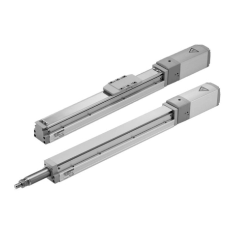
Electric actuator Rod
ESD2 Series
Compatibility function allows the controller, actuator and cable to be
freely combined
The electric actuator that works like a pneumatic cylinder
Motor sizes: 42 / 56
Actuator specications
*1: The maximum load capacity decreases when the speed increases. For more details, refer to the vertical and horizontal load capacity charts and graphs in
the next page.
In addition, a static or dynamic load moment cannot be applied to the rod. Use a linear guide, etc., to prevent a radial load from being placed on the rod.
Note: the numbers in ( ) indicate the product weight with the brake
Descriptions ESD2-35 ESD2-45 ESD2-55
Actuator Rod
Motor Stepping motor
Encoder Incremental
Drive system Rolling ball screw
Outer diameter 8 mm
Rolling ball screw
Outer diameter 12 mm
Motor size 42 56
Screw lead mm 6 12 6 12 6 12
Stroke mm 50, 100, 150 50, 100, 150, 200 50, 100, 150, 200
250, 300
Operation speed range mm/s 15 to 300 30 to 600 15 to 300 30 to 600 15 to 200 30 to 400
Operation acceleration/deceleration speed range
m/s21.0 to 3.0
Repeatability mm ±0.02
Lost motion mm 0.1 or less
Max. load capacity
*1
Horizontal kg 33 16 33 16 67 34
Vertical kg 10 4 10 4 15 6.5
Maximum pressing force N 220 110 220 110 640 320
Motor power supply voltage 24 VDC±10%
Motor section maximum instantaneous current
A 2.7 2.7 4
Brake
Type Non-excitation operation
Power supply voltage
24 VDC±10%
Power consumption
W 6.1 7.2
Holding force N 140 70 140 70 610 305
Insulation resistance 10 MΩ or higher 500 VDC
Withstand voltage 500 VAC for 1 minute
Operating ambient temperature 0 to 40°C (no freezing)
Operating ambient humidity 35 to 80% RH (no condensation)
Storage ambient temperature -10 to 50°C (no freezing)
Storage ambient humidity 35 to 80% RH (no condensation)
Atmosphere No corrosive gas, explosive gas, or dust
Degree of protection IP4X
Weight
Body size
Motor mounting direction
50 st 100 st 150 st 200 st 250 st 300 st
ESD2-35
E1.3
(1.7)
1.5
(1.9)
1.6
(2.0) ---
R/L/D 1.5
(1.8)
1.7
(2.0)
1.8
(2.1)
ESD2-45
E1.7
(2.1)
2.0
(2.4)
2.2
(2.6)
2.5
(2.9) - -
R/L/D 1.9
(2.2)
2.2
(2.5)
2.4
(2.7)
2.7
(3.0)
ESD2-55
E3.0
(3.7)
3.4
(4.1)
3.8
(4.5)
4.1
(4.8)
4.5
(5.2)
4.9
(5.6)
R/L/D 3.5
(4.1)
3.9
(4.5)
4.3
(4.9)
4.6
(5.2)
5.0
(5.6)
5.4
(6.0)
(kg)
13
Other manuals for ERL2 Series
1
This manual suits for next models
6
Table of contents
Other CKD Controllers manuals

CKD
CKD KBX-T5 User manual

CKD
CKD ECG Series User manual

CKD
CKD Rapiflow FCM Series User manual

CKD
CKD KBX-30 User manual

CKD
CKD ECR Series User manual

CKD
CKD ESSD Series User manual

CKD
CKD FLCR-G Series User manual

CKD
CKD FP Series User manual

CKD
CKD PARECT MEVT Series User manual

CKD
CKD ECS Series User manual