SRS Labs SIM965 Operation manual

Operation and Service Manual
Bessel & Butterworth Filter
SIM965
Stanford Research Systems
Revision 1.7 •August 3, 2011

Certification
Stanford Research Systems certifies that this product met its published specifications at the time
of shipment.
Warranty
This Stanford Research Systems product is warranted against defects in materials and workman-
ship for a period of one (1) year from the date of shipment.
Service
For warranty service or repair, this product must be returned to a Stanford Research Systems
authorized service facility. Contact Stanford Research Systems or an authorized representative
before returning this product for repair.
Information in this document is subject to change without notice.
Copyright c
Stanford Research Systems, Inc., 2005 – 2011. All rights reserved.
Stanford Research Systems, Inc.
1290–D Reamwood Avenue
Sunnyvale, CA 94089 USA
Phone: (408) 744-9040 •Fax: (408) 744-9049
Printed in U.S.A. Document number 9-01597-903
SIM965 Bessel & Butterworth Filter

Contents
General Information iii
Safety and Preparation for Use . . . . . . . . . . . . . . . . iii
Symbols ............................. iv
Notation ............................. v
Specifications .......................... vi
1 Operation 1 – 1
1.1 Overview.......................... 1–2
1.2 Nominal transfer functions . . . . . . . . . . . . . . . 1 – 3
1.3 Front-Panel Operation . . . . . . . . . . . . . . . . . . 1 – 8
1.4 ClockStopping ...................... 1–9
1.5 SIMInterface........................ 1–10
2 Remote Operation 2 – 1
2.1 Index of Common Commands . . . . . . . . . . . . . . 2 – 2
2.2 Alphabetic List of Commands . . . . . . . . . . . . . . 2 – 4
2.3 Introduction ........................ 2–6
2.4 Commands......................... 2–6
2.5 StatusModel........................ 2–16
3 Circuitry 3 – 1
3.1 Circuit Descriptions . . . . . . . . . . . . . . . . . . . . 3 – 2
3.2 PartsLists ......................... 3–4
3.3 Schematic Diagrams . . . . . . . . . . . . . . . . . . . 3 – 6
i

ii Contents
SIM965 Bessel & Butterworth Filter

General Information
The SIM965 Analog Filter, part of Stanford Research Systems’
Small Instrumentation Modules family, is a continuous-time, pro-
grammable filter capable of high-pass and low-pass operation as a
Butterworth or Bessel filter.
Safety and Preparation for Use
The front-panel input, front-panel output, and the rear-panel output
coaxial (BNC) connectors in the SIM965 are referenced to the Earth,
and their outer casings are grounded. No dangerous voltages are
generated by the module.
Do not exceed ±15 volts to the Earth at the center terminal of any BNC
WARNING connector. Do not install substitute parts or perform unauthorized
modifications to this instrument.
The SIM965 is a single-wide module designed to be used inside the
SIM900 Mainframe. Do not turn on the power until the module is
completely inserted into the mainframe and locked in place.
iii

iv General Information
Symbols you may Find on SRS Products
Symbol Description
Alternating current
Caution - risk of electric shock
Frame or chassis terminal
Caution - refer to accompanying documents
Earth (ground) terminal
Battery
Fuse
On (supply)
Off (supply)
SIM965 Bessel & Butterworth Filter

General Information v
Notation
The following notation will be used throughout this manual.
A warning means that injury or death is possible if the instructions
WARNING are not obeyed.
A caution means that damage to the instrument or other equipment
CAUTION is possible.
Typesetting conventions used in this manual are:
•Front-panel buttons are set as [Button];
[Adjust ] is shorthand for “[Adjust ] & [Adjust ]”.
•Front-panel indicators are set as Overload.
•Remote command names are set as *IDN?.
•Literal text other than command names is set as OFF.
Remote command examples will all be set in monospaced font. In
these examples, data sent by the host computer to the SIM965 are set
as straight teletype font, while responses received by the host
computer from the SIM965 are set as slanted teletype font.
SIM965 Bessel & Butterworth Filter

vi General Information
Specifications
Performance Characteristics
Min Typ Max Units
Input Impedance 1 MΩ
Coupling AC or DC
Gain 1×
AC-coupling time const. 1 s
Range, 48 dB/oct Butterworth −5+5 V
36 dB/oct Butterworth −7+7
all others −10 +10
Filter Band low-pass or high-pass
Cutofffrequency 1.00 5 ×10⁵Hz
Resolution 3 digits
Accuracy −1+1 %
Type Butterworth, Bessel
Rolloff12, 24, 36, 48 dB/octave
Output Noise <200µVrms (1 MHz bandwidth)
THD 0.01 % (−80 dB) at 1 kHz
Operating Temperature 0 40 ◦C, non-condensing
Power +5,±15 V DC
Supply current, +5 V 100 mA
±15 V 300 mA
General Characteristics
Interface Serial (RS-232) through SIM interface
Connectors BNC (2 front, 1 rear)
DB–15 (male) SIM interface
Weight 3 lbs
Dimensions 1.500 W×3.600 H×7.000 D
SIM965 Bessel & Butterworth Filter

1 Operation
This chapter gives you the necessary information to get started
quickly with the SIM965 Analog Filter.
In This Chapter
1.1 Overview ......................... 1–2
1.2 Nominal transfer functions . . . . . . . . . . . . . . . 1 – 3
1.2.1 Butterworth filters . . . . . . . . . . . . . . . . 1 – 3
1.2.2 Bessel filters . . . . . . . . . . . . . . . . . . . . 1 – 3
1.2.3 High-pass filters . . . . . . . . . . . . . . . . . 1 – 6
1.3 Front-Panel Operation . . . . . . . . . . . . . . . . . . 1 – 8
1.3.1 Frequency..................... 1–8
1.3.2 Type ........................ 1–8
1.3.3 Filter ........................ 1–8
1.3.4 Slope........................ 1–8
1.3.5 Input........................ 1–8
1.3.6 Output....................... 1–9
1.4 ClockStopping...................... 1–9
1.5 SIMInterface ....................... 1–10
1.5.1 SIM interface connector . . . . . . . . . . . . . 1 – 10
1.5.2 Direct interfacing . . . . . . . . . . . . . . . . . 1 – 10
1–1

1–2 Operation
1.1 Overview
The SIM965 Analog Filter is a continuous-time, digitally-programmable
filter with fully analog signal paths. By using a modified state-
variable circuit design, the SIM965 provides a variety of programmed
filter configurations. From the front panel, the user can select a But-
terworth filter, for maximum passband gain flatness, or a Bessel
filter, for minimum pulse overshoot and constand time delay in the
passband. The user can also select either a low-pass or high-pass
filter, and change the order of the filter between 2nd, 4th, 6th, or 8th
order, corresponding to 12, 24, 36 or 48 dB/octave roll-offin the stop
band.
For any filter configuration, a single continuous parameter, the “cut-
offfrequency,” fccan be set with 3-digit resolution (and ±1 % ac-
curacy) in the range of 1 Hz to 500 kHz. For Butterworth filters, fc
corresponds to the frequency at which the filter response is −3 dB. For
Bessel filters, fcis determined so that the far-stop-band attenuation
slope asymptotically approaches that of the Butterworth filter.
Figure 1.1: The SIM965 front and rear panels.
SIM965 Bessel & Butterworth Filter

1.2 Nominal transfer functions 1–3
1.2 Nominal transfer functions
The SIM965 circuitry is configured to provide a near-ideal Butter-
worth or Bessel filter transfer function for the user.
1.2.1 Butterworth filters
For a Butterworth filter, the nominal transfer function for an nth-
order low pass filter is given by:
Gn(f)=s1
1+η2n(1.1)
where, for low-pass filters, η=(f/f0), and f0=fc, the −3 dB fre-
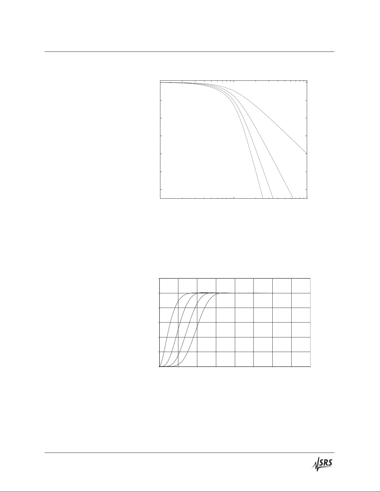
quency of the response function. Figures 1.2 and 1.3 show the fre-
quency and step response for Butterworth low-pass filters.
1.2.2 Bessel filters
For Bessel filters, the nominal transfer function for an nth-order low
pass filter is given by:
Gn(f)=v
t1
BN
boN2+PN
boN2(1.2)
where, for low-pass filters, η=(f/f0), and BN,PN, and boNare
determined iteratively, based on
BN=(2N−1)B(N−1) −η2B(N−2)
with B0=1, B1=1,
PN=(2N−1)P(N−1) −η2P(N−2)
with P0=0, P1=η, and
boN=(2N−1) ∗bo(N−1)
with bo0=1. Figures 1.4 and 1.5 show the frequency and step
response for Bessel low-pass filters.
The SIM965 uses a frequency normalization for Bessel filters such
that the far-stop-band response asymptotically approaches that of
the same-order Butterworth filter. Table 1.1 gives the scaling factors
to obtain the formal f0(needed for the Bessel formulae) and the actual
−3 dB frequency, in terms of the SIM965 setting fc. For example, for a
6-pole low-pass Bessel filter with fc=100 Hz can be calculated using
f0=0.21409 ×fc, or 21.409 Hz.
SIM965 Bessel & Butterworth Filter

1–4 Operation
-60
-50
-40
-30
-20
-10
0
100 Hz 1 kHz 10 kHz
12 dB/octave
24
36
48 dB/octave
Frequency
Response [dB]
Figure 1.2: The nominal frequency response for Butterworth low-
pass filters of various orders. All filters are tuned to fc=1 kHz.
0
0.2
0.4
0.6
0.8
1
1.2
0 0.5 1 1.5 2 2.5 3 3.5 4
Time (ms)
Response
48 dB/octave
36
24
12
Figure 1.3: The nominal step response for Butterworth low-pass
filters of various orders. All filters are tuned to fc=1 kHz.
SIM965 Bessel & Butterworth Filter
1.2 Nominal transfer functions 1–5
-60
-50
-40
-30
-20
-10
0
100 Hz 1 kHz 10 kHz
12 dB/octave
24
36
48 dB/octave
Frequency
Response [dB]
Figure 1.4: The nominal frequency response for Bessel low-pass fil-
ters of various orders. All filters are tuned to fc=1 kHz.
0
0.2
0.4
0.6
0.8
1
1.2
0
0.5 1 1.5 2 2.5 3 3.5 4
Time (ms)
Response
48 dB/octave
36
24
12
Figure 1.5: The nominal step response for Bessel low-pass filters of
various orders. All filters are tuned to fc=1 kHz.
SIM965 Bessel & Butterworth Filter

1–6 Operation
Order f0f−3 dB
2 0.577 39 ×fc0.786 2 ×fc
4 0.312 43 ×fc0.660 4 ×fc
6 0.214 09 ×fc0.578 7 ×fc
8 0.162 83 ×fc0.517 7 ×fc
Table 1.1: Bessel filter normalization factors
1.2.3 High-pass filters
To obtain the formulae for a high-pass Butterworth filter, simply
substitute η=(f0/f) into Equation 1.1.
For a high-pass Bessel filter, one similarly substitutes η=(f/f0) into
Equation 1.2. However, the scaling factors from Table 1.1 must be in-
verted. For example, a 6–pole high-pass Bessel filter with fc=100 Hz
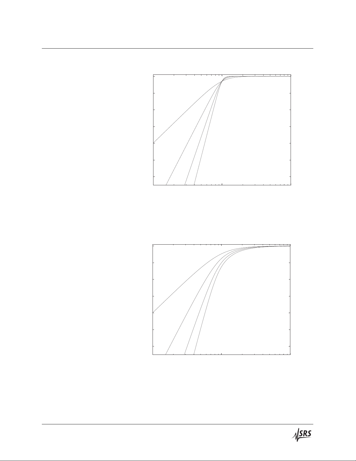
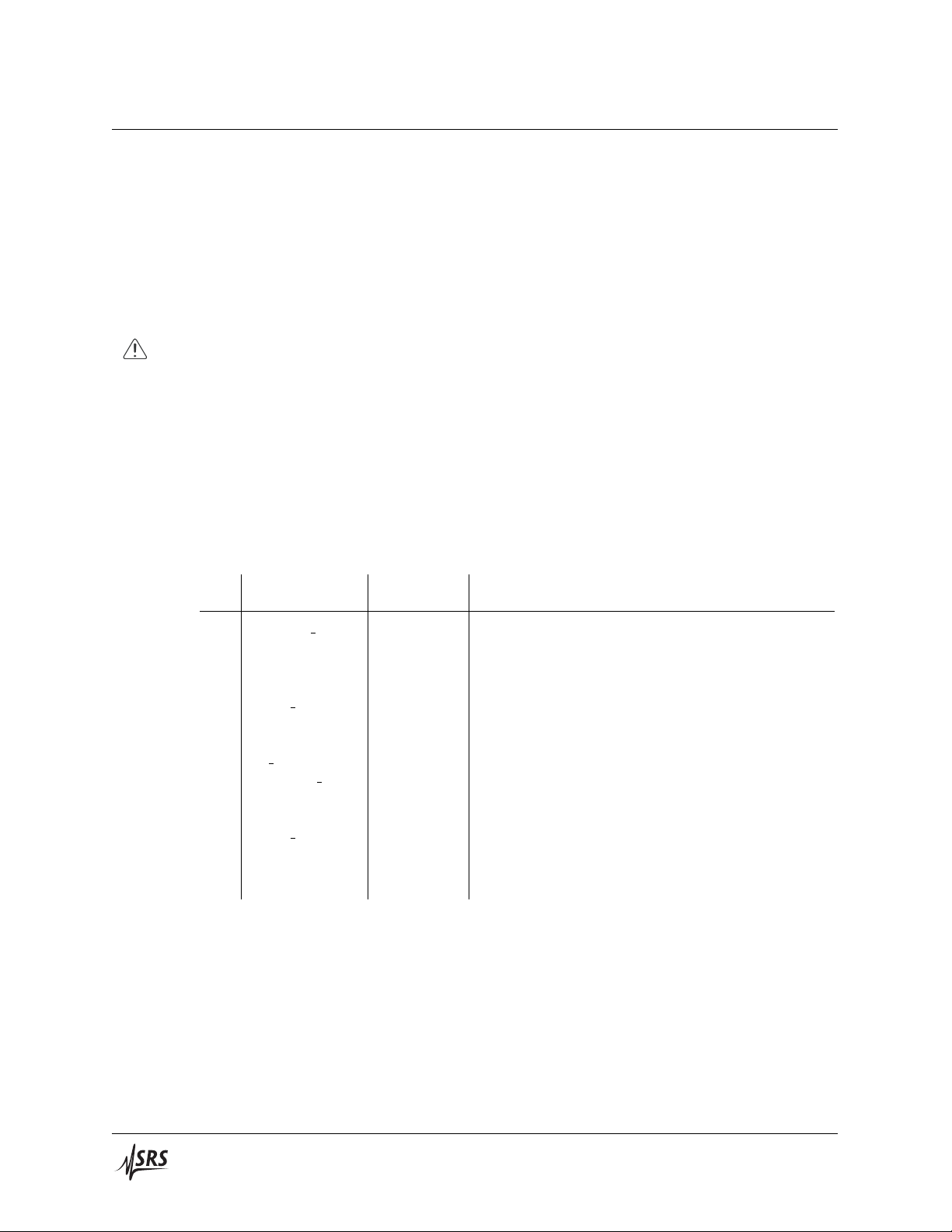
can be calculated using f0=fc÷0.21409, or 467.09 Hz. Figures 1.6
and 1.7 show the frequency response for Butterworth and Bessel
high-pass filters.
SIM965 Bessel & Butterworth Filter
1.2 Nominal transfer functions 1–7
-60
-50
-40
-30
-20
-10
0
100 Hz 1 kHz 10 kHz
12 dB/octave
24
36
48 dB/octave
Frequency
Response [dB]
Figure 1.6: The nominal frequency response for Butterworth high-
pass filters of various orders. All filters are tuned to fc=1 kHz.
-60
-50
-40
-30
-20
-10
0
100 Hz 1 kHz 10 kHz
12 dB/octave
24
36
48 dB/octave
Frequency
Response [dB]
Figure 1.7: The nominal frequency response for Bessel high-pass
filters of various orders. All filters are tuned to fc=1 kHz.
SIM965 Bessel & Butterworth Filter

1–8 Operation
1.3 Front-Panel Operation
All settings of the SIM965 can be set from the front panel (see Fig-
ure 1.1).
1.3.1 Frequency
The cutofffrequency can be incremented or decremented using the
[Freq. ] buttons. Pressing either [Freq. ] or [Freq. ] once will cause
the least significant digit in the display to increment (or decrement)
by one. If the button is held down, the display will begin to change
at a steadily-increasing rate, accelerating to allow large fcchanges to
be made easily. Note that the circuitry is not reprogrammed until the
button is released.
1.3.2 Type
The [Type] button allows the user to toggle between Butterworth or
Bessel filter type.
1.3.3 Filter
The [Filter] button allows the user to toggle between high pass or
low pass filter pass band.
1.3.4 Slope
The [Slope] button allows the user to cycle through the four available
stop band roll-offrates: 12, 24, 36 and 48 dB/octave.
1.3.5 Input
Input signals to the SIM965 at the front-panel BNC connector in the
“Input” block. If the input signal exceeds the specified ±10 V range,
the Ovld indicator will light and remain on as long as the signal
exceeds the specified input range.
1.3.5.1 Couple
The [Coupling] button allows the user to toggle the input coupling
of the SIM965 between AC and DC coupling. When AC-coupled, the
input is high-pass filtered by a single-pole RC filter with a 1 second
time constant.
SIM965 Bessel & Butterworth Filter

1.4 Clock Stopping 1–9
1.3.6 Output
The filtered signal is available from the SIM965 at the front-panel
BNC connector in the “Output” block. A second output connector
is available on the rear panel as well. Each output is (separately)
connected the filter circuitry through an internal 50 Ωresistor.
1.4 Clock Stopping
The microprocessor clock of the SIM965 stops if the module is idle,
“freezing” the digital circuitry. The following actions “wake up” the
clock:
1. A power-on.
2. A press of a front-panel button.
3. Activity (send or receive) at the remote interface.
4. An overload.
The clock runs for as long as is necessary to complete a filter setting
adjustment, or to communicate the output of a query through the
remote interface. However, the clock will remain active for as long
as the overload condition exists.
This default behavior can be modified with the remote com-
mand AWAK. Setting AWAK ON will prevent the clock from stopping.
The module returns to AWAK OFF upon power-on.
SIM965 Bessel & Butterworth Filter
1 – 10 Operation
1.5 SIM Interface
The primary connection to the SIM965 Analog Filter is the rear-panel
DB–15 SIM interface connector. Typically, the SIM965 is mated to
a SIM900 Mainframe via this connection, either through one of the
internal Mainframe slots, or the remote cable interface.
It is also possible to operate the SIM965 directly, without using the
SIM900 Mainframe. This section provides details on the interface.
The SIM965 has no internal protection against reverse polarity, missing
CAUTION supply, or overvoltage on the power supply pins. Misapplication of power
may cause circuit damage. SRS recommends using the SIM965 together
with the SIM900 Mainframe for most applications.
1.5.1 SIM interface connector
The DB–15 SIM interface connector carries all the power and commu-
nications lines to the instrument. The connector signals are specified
in Table 1.2
Direction
Pin Signal Src ⇒Dest Description
1 SIGNAL GND MF ⇒SIM Ground reference for signal
2−STATUS SIM ⇒MF Status/service request (GND =asserted, +5 V=idle)
3 RTS MF ⇒SIM HW handshake (unused in SIM965)
4 CTS SIM ⇒MF HW handshake (unused in SIM965)
5−REF 10MHZ MF ⇒SIM 10 MHz reference (no connection in SIM965)
6−5 V MF ⇒SIM Power supply (no connection in SIM965)
7−15 V MF ⇒SIM Power supply
8 PS RTN MF ⇒SIM Power supply return
9 CHASSIS GND Chassis ground
10 TXD MF ⇒SIM Async data (start bit =“0”= +5 V; “1” =GND)
11 RXD SIM ⇒MF Async data (start bit =“0”= +5 V; “1” =GND)
12 +REF 10MHz MF ⇒SIM 10 MHz reference (no connection in SIM965)
13 +5 V MF ⇒SIM Power supply
14 +15 V MF ⇒SIM Power supply
15 +24 V MF ⇒SIM Power supply (no connection in SIM965)
Table 1.2: SIM Interface Connector Pin Assignments, DB-15
1.5.2 Direct interfacing
The SIM965 is intended for operation in the SIM900 Mainframe, but
users may wish to directly interface the module to their own systems
without the use of additional hardware.
SIM965 Bessel & Butterworth Filter

1.5 SIM Interface 1 – 11
The mating connector needed is a standard DB–15 receptacle, such as
Tyco part # 747909–2 (or equivalent). Clean, well-regulated supply
voltages of +5, ±15 V DC must be provided, following the pin-out
specified in Table 1.2. Ground must be provided on pins 1 and 8,
with chassis ground on pin 9. Note that internally the SIM965 ties
all three of these terminals, pins 1, 8, and 9, together to form the
internal ground. The −STATUS signal may be monitored on pin 2
for a low-going TTL-compatible output indicating a status message.
1.5.2.1 Direct interface cabling
If the user intends to directly wire the SIM965 independent of the
SIM900 Mainframe, communication is usually possible by directly
connecting the appropriate interface lines from the SIM965 DB–15
plug to the RS-232 serial port of a personal computer.1Connect RXD
from the SIM965 directly to RD on the PC, TXD directly to TD. In
other words, a null-modem style cable is not needed.
To interface directly to the DB–9 male (DTE) RS-232 port typically
found on contemporary personal computers, a cable must be made
with a female DB–15 socket to mate with the SIM965, and a female
DB–9 socket to mate with the PC’s serial port. Separate leads from
the DB–15 need to go to the power supply, making what is sometimes
know as a “hydra” cable. The pin-connections are given in Table 1.3.
DB–15/F to SIM965 Name
DB–9/F
10 → 3 TxD
11 → 2 RxD
5 Computer Ground
to P/S
7→ −15 VDC
13 → +5 VDC
14 → +15 VDC
1,8,9 → Ground (chassis, & P/S return)
Table 1.3: SIM965 Direct Interface Cable Pin Assignments
1Although the serial interface lines on the DB-15 do not satisfy the minimum
voltage levels of the RS-232 standard, they are typically compatible with desktop
personal computers
SIM965 Bessel & Butterworth Filter

1 – 12 Operation
1.5.2.2 Serial settings
The initial serial port settings at power-on are: 9600 Baud, 8–bits, no
parity, 1 stop bit, and no flow control. The parity can be changed
with the PARI remote command.
SIM965 Bessel & Butterworth Filter
Table of contents
Other SRS Labs Water Filtration System manuals

Popular Water Filtration System manuals by other brands


Axi
Axi STS 6000 P-35 INSTRUCTION, OPERATING, & MAINTENANCE MANUAL

Oasis
Oasis PITCHER user guide

ELECRAFT
ELECRAFT KDSP2 Assembly and operating instructions

dosatron
dosatron D25RE2 Maintenance manual

Aquatec Equipment
Aquatec Equipment AquaPRO AP5000UV user manual

Euromate
Euromate DFI AIR CLEANER installation manua


