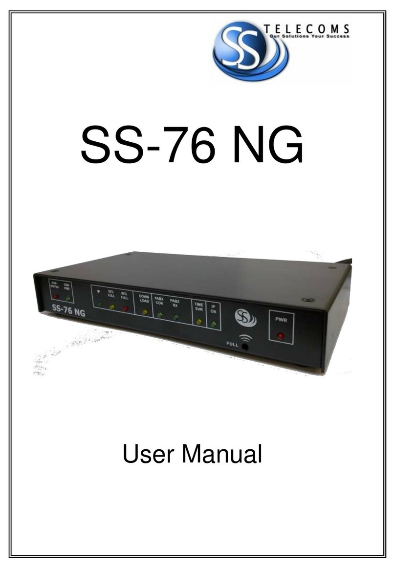
SS Telecoms SS-77 uTMS User manual

SS-77 uTMS
User Manual

SS-77 uTMS USER MANUAL
DOC. NO: SS-77 uTMS (REVISION 08) Page 2 of 37
REVISION HISTORY
Revision 01 Original document 2009/05/19
Revision 02 PHO command 2009/10/01
Revision 03 IPS PABX 2010/01/21
Revision 04 ECC and PRT 2010/06/24
Revision 05 PABX Management 2011/05/13
Revision 06 Using NG Tool 2011/07/06
Programming Scenarios
Revision 07 FTP CLIENT
MMI password 2011/07/22
Revision 08 Through Connection 2011/08/12

SS-77 uTMS USER MANUAL
DOC. NO: SS-77 uTMS (REVISION 08) Page 3 of 37
CONTENTS
1. PURPOSE ........................................................................................... 4
2. FEATURES .......................................................................................... 4
3. DESCRIPTION OF FRONT PANEL ......................................................... 5
4. DESCRIPTION OF REAR PANEL ........................................................... 6
5. APPLICATIONS ................................................................................... 7
6. FACTORY SETTINGS ........................................................................... 8
7. GETTING STARTED ............................................................................. 9
8. USING THE NG PROGRAMMING TOOL .............................................. 9
9. PROGRAMMING SCENARIOS AND EXAMPLES .................................. 16
10. COMMANDS.................................................................................... 26
10.1. PA X MANAGEMENT MODE ........................................................... 32
10.2. TCP CALL- ACK-MODE .................................................................... 32
10.3. FTP TMS CLIENT .............................................................................. 33
10.4. THROUGH CONNECTION – LAN TO SERIAL PORT 1 .......................... 34
10.5. REMOTE ACCESS TO SERIAL CONNECTED EQUIPMENT .................... 35
11. DONGLE OPERATION ....................................................................... 35
12. QUICK SETUP GUIDES ...................................................................... 36
12.1. ASCII DATA COLLECTION VIA SERIAL PORT ...................................... 36
12.2. DATA COLLECTION ON ALCATEL 4400 / OMNI PCX .......................... 36
12.3. DATA RETRIEVAL USING UDP LOGGER ............................................. 36
13. CONTACT DETAILS ........................................................................... 37

SS-77 uTMS USER MANUAL
DOC. NO: SS-77 uTMS (REVISION 08) Page 4 of 37
1. PURPOSE
The purpose of the SS-77 is that of a multifunction data buffer. It is designed to
collect data from a variety of sources (primarily PABXs) using various protocols.
The data can then be retrieved from the SS-77 using a number of different
methods. This allows the buffer to be used where the link between the data
processing solution and the data source may be intermittent or otherwise prone to
data loss.
The SS-77 can also be used to provide remote access to serially connected
equipment (RS-232) by Ethernet.
The data can optionally be time stamped by the buffer.
2. FEATURES
FEATURES
•
Memory capacity of 8 megabytes
•
Battery backup
•
LEDs to indicate buffer status
•
10MBit or 100MBit Ethernet operation
•
Dongle Function
•
Built-In tests for
Supply voltages
LEDs
•
Hardware Reset Button
Allows loading of default settings
•
Audio Beeper
Alerts users to status changes
Warnings of system failures
•
Data collection options
Via Serial ports
oPort 1 - Baud rates from 1200
baud to 115200 baud
oPort 2 - Baud rates from 1200
baud to 19200 baud
Via Ethernet
oActive TCP/IP
oPassive TCP/IP
o
UDP (e.g. Syslog)
•
Data retrieval
Via Serial Port
oAuto Dump using handshake line
oASCII protocol (‘S<enter>’ to
retrieve a record)
Via Ethernet
oNetLog standard protocol
oUdpLog standard protocol
oAuto Dump on Ethernet
connection.
•
Protocol translation
Binary
ASCII
STX-ETX
RoboDog
•
Supports the following Internet Protocols
DHCP
SNTP
NBNS
DNS
TCP
UDP

SS-77 uTMS USER MANUAL
DOC. NO: SS-77 uTMS (REVISION 08) Page 5 of 37
3. DESCRIPTION OF FRONT PANEL
The Front Panel
BEEPER
The beeper sounds when the buffer is 95% full and also indicates status changes.
LED INDICATORS
LED INDICATORS
DOWN LOAD
•
Indicates that the logging server has responded to buffer.
•ON when logging server has responded to buffer or a TCP session is
connected to Socket 0 (either MMI or NetLog), flicks off when data sent.
•Off when Serial connected, flashes on when data sent.
HEARTBEAT
•
Flashing indicates that the unit is operational.
•Double flash indicates some data in the buffer (64 or more characters)
•Triple flash indicates more data in buffer (2048 or more characters)
50% full
•
This LED flashes when buffer is 50% full.
80% full
•
This LED flashes when buffer is 80% full.
IP OK
•
Indicates that the IP address is OK or that DHCP was successful if
enabled.
TIME SVR
•
Indicates the time server returned a valid time.
PABX RX
•
Indicates when data is received from PABX, either via the serial or via the
LAN interface, thereby providing visual confirmation that the buffer is
receiving data from the PABX.
PABX CON
•
Indicates when IP connection is active to the PABX.
PWR
•
This LED indicates that power is being received from the external 12 volt
power supply.

SS-77 uTMS USER MANUAL
DOC. NO: SS-77 uTMS (REVISION 08) Page 6 of 37
4. DESCRIPTION OF REAR PANEL
The rear panel
RESET SWITCH
Used for resetting the buffer and the Network Interface. It is also used to restore
default settings by pressing the reset button and holding it for 6 seconds. (Until the
buffer beeps) – Refer to Default Settings
POWER SUPPLY - External
oExternal power supply
oMinimum Voltage = 10 VDC
oMaximus Voltage = 20 VDC
oCurrent requirements = Under 100 mA
ETHERNET RJ-45
oGreen LED indicates LINK is up
oYellow LED indicates 100MBit speed active
SERIAL 2 (Default serial logging port)
oBaud rates from 1200 baud to 19200 baud
oOptions: 8N1, 7E1, 7O1, 7N1, 8N2, 7E2, 7O2, 7N2
oHandshake output for buffer full / power down
The Handshake will be set inactive when the Flash Memory is full and there
is capacity for 100 characters left in the input buffer.
To prevent continuous up/down the Handshake will be activated when in
input buffer has been emptied.
If the data is not stopped by the handshaking line then excess data will be
lost.
SERIAL 1 (Default serial MMI port)
oUsed to access equipment such as FCT Mux
oBaud rates from 1200 baud to 115200 baud
oOnly 8N1, 7E1, 7O1, 8N2, 7E2, 7O2, 7N2
BATTERY BACKUP – Internal
oAAA NiMH 500mAH to 1000mAH rechargeable batteries.
oBatteries are replaceable by the end user
Note: Battery backup allows:
Orderly shutdown of Ethernet connections
Continued logging on Serial Port for up to 2 days
Date / Time (RTC) for extended period up to 2 weeks

SS-77 uTMS USER MANUAL
DOC. NO: SS-77 uTMS (REVISION 08) Page 7 of 37
5. APPLICATIONS
BASIC SETUP
Serial to LAN
LAN to Serial
The following example shows how data can
be collected from the PABX system using a
serial interface. The TMS software then
collects data via the LAN interface using
TCP
or UDP protocol.
Refer to section 9.Programming Scenarios
and Examples.
The following example shows how data can be
collected from the PABX system using the
LAN interface. The TMS software then collects
data via the serial interface.
Refer to section 9.Programming Scenarios and
Examples.
LAN to LAN
Remote access to serially connected
equipment. (Etc. FCT Mux)
The following example shows how data can
be collected from the PABX system using a
LAN interface. The TMS software then also
collects the data via the LAN interface.
Refer to section 9.Programming Scenarios
and Examples.
The following example shows how a PC can
access a remote serial device via the LAN
interface of the SS-77.
Refer to section 11. Remote Access to Serial
Connected Equipment.

SS-77 uTMS USER MANUAL
DOC. NO: SS-77 uTMS (REVISION 08) Page 8 of 37
6. FACTORY SETTINGS
1. The Buffer can be set to default settings by pressing the reset button and
holding it for 6 seconds. (Until the buffer beeps).
2. Alternatively, if serial communications has been established the command
‘DEFDAT’ can be issued.
DEFAULT VALUES
Setting Command
Value
Serial 1 baud rate SB1 115200 baud
Serial 2 baud rate SB2 19200 baud
Serial 2 data/parity S2P 8N
Default MMI port MMP Serial 1
Default Logging Port SDL Serial 2
PABX translation XLT ASCII
Short Record Elimination length SRE 1
Beeper Volume BPV 50%
Auto Dump SAD Disabled
Auto Dump Timeout SAT 10 seconds
RoboDog Sync Char RSY ‘R’
RoboDog Character count RCT 3
TMS Server (UdpLog) TMI Blank, Not Set.
Time Server STS time-a.nist.gov
Time Zone STZ -120 minutes for South Africa
DHCP UDH Enabled
Use Ten MBit UTM Off
Local IP address LIP 192.168.0.234
Subnet mask SNM 255.255.255.0
Gateway GWA 0.0.0.0
DNS IP address DNS 0.0.0.0
NetBIOS Name NBN ‘SS-77-ABCDEF’ where ‘ABCDEF’ are the last 6 digits
of the MAC address
Buffer Name (UdpLog) BID ‘SSABCDEF’ with ABCDEF the last 6 digits of the MAC
address
Socket 0 Connection Type PRT TCP Passive
Socket 0 Local Port LPT 23 – Telnet address for LAN access
Socket 2 (UdpLog Socket) Port LPT 12345 –
must be something other than 1122 which is the
remote port
Echo ECHO Off

SS-77 uTMS USER MANUAL
DOC. NO: SS-77 uTMS (REVISION 08) Page 9 of 37
7. GETTING STARTED
7.1.As delivered from the factory the buffer can be accessed for setup in the following ways:
7.1.1. On serial port 1 using a communications package such as HyperTerminal or using
the NG Tool. The port settings are 115200 baud, 8 data bit, no parity, 1 stop with
hardware flow control disabled.
7.1.2. Via LAN. Use an Ethernet Telnet terminal package. The SS-77 defaults to using
DHCP with its NetBIOS Name set to SS-77- followed by the last 6 digits of the
MAC address. For example, if the MAC address is 00:21:44:12:34:56 the NBNS
name is ‘SS-77-123456’.
7.1.3. The buffer can also be accessed and programed using the NG Buffer Tool. Please
see section 8.1 “Using the NG Software Programming Tool.”
7.2. Character Echo. To function correctly with NetLog and other data collection packages the local
echo of typed characters is disabled. In order to view what is being typed it is necessary to
enable local echo. The simplest way to do this is to enter the command “ECHO ON”. This will
automatically be cancelled when the SS-77 is reset. Alternatively one can enable echo in
HyperTerminal by selecting:
“Properties->Settings->ASCII Setup->Echo typed characters locally”
This session can be saved for future use as SS-77 and the settings will be retained.
8. USING THE NG PROGRAMMING TOOL
Note: The NG Programming Tool can be downloaded from SS Telecoms web site.
8.1. NG MAIN TERMINAL SCREEN
NG Tool Main Screen
The SS
-
77 Tool can be used as a terminal
program enabling the user to issue commands via the
terminal screen. The main purpose of the Tool is to make programing of the buffer user-friendly.
Setting Description
Main Screen

SS-77 uTMS USER MANUAL
DOC. NO: SS-77 uTMS (REVISION 08) Page 10 of 37
Menu Items
Setup
This will open the Setup configuration screen explained below.
File
When upgrading the firmware of the SS
-
77. Use the file men
u to
select the firmware file to be uploaded. These type of file are
normally has an HEX extension.
PBX Mode
PABX Management Mode
This mode allows remote access to a PABX Ethernet port through
the buffer. It allows commands to be passed from either the Serial
MMI port or the Ethernet MMI port to the PABX Ethernet port.
The buffer will attempt to establish a connection to the PABX using
the ‘LOG LAN IP addr’ with the specified port number. When the
connection is established the buffer will respond with:
PMS: Connected <port>
A twenty second timer is started so that if no commands are sent to
the PABX the link will be disconnected with the message:
PMS: Disconnect
Front
To change the font size and type of the text displayed in the
terminal screen.
Colour To change the terminal background colour and text colour.
Close
Closes the NG Tool application.
Remote
Firmware Upload
This
setting
should
be enabled when the firmware
updated
is done
through an
TCP(LAN) connection.
Host Name &
Port
The IP or Hostname to make a connection to.
This would normally be the IP Address or Hostname of the buffer. The default
MMI(Programming Interface) and Buffer port is 23.
Use the Connect and Disconnect buttons for TCP.
Com Port
Com Port Use the Dropdown box to select the com port.
This is com port to use on the local PC for connecting to the buffer.
Baud Rate
Baud rate to use.
The default baud rate to connect to Serial 1 of the buffer is 115200.

SS-77 uTMS USER MANUAL
DOC. NO: SS-77 uTMS (REVISION 08) Page 11 of 37
8.2. NG TOOL SETTINGS SCREEN
NG Tool Settings Screen
This screen is used to configure and upload the SS-77 settings
Setting
Description
Settings
Port Settings
Serial 1 Baud
Set the Serial Port 1 baud rate.
This is the default MMI port. The
buffer can be accessed and programmed via this serial port. The
default baud rate is 115200
Serial 2 Baud
Set the Serial Port 2 baud rate. This is the default logging port for
collecting data. The PABX serial output would normally be
connected to this port. Default baud rate is 19200
Serial 2 Parity Sets the number of data bits and parity format for Serial Port 2.
Through
Connection
The SS-77 has the ability to route the LAN socket #1 through the MMI serial port 1.
Amongst other things this allows LAN access to the serial port on a PABX.
Note: This mode of operation is only possible when LAN logging of the PABX is not
used.
Enable Trough
Connect
This will enable a through connection between the LAN socket
with the TCP port that is specified and the Serial Port 1of the SS-
77. Note: When enabling this feature the Serial MMI port 1 will be
set to Silent Mode.
LAN Local Port
Set the local port to
listen for incoming connections. T
his can be
any number from 1 to 65524. Note that certain ports are
commonly used for tasks such as FTP, SMTP etc. so care needs
to be taken in choosing a suitable port number.

SS-77 uTMS USER MANUAL
DOC. NO: SS-77 uTMS (REVISION 08) Page 12 of 37
Logging
Settings
Default MMI Port
This sets the serial port to be used for programming of the buffer
also known as the MMI Port. Because the buffer can also be
programmed via the LAN interface an incoming connection on
the TCP port will automatically become the MMI port. While the
TCP link is established the serial port control will be disabled.
The default MMI Port is Serial 1.
Note: When the Through Connection feature is enabled the
Serial MMI port 1 will be set to Silent Mode.
Date Insertion This is used to enable the insertion of the Date and Time either
before the record or after the record.
AutoDump
Enable Auto Dump. Default is ‘OFF’. When enabled the buffer
will dump its stored data when the Serial 1 ha
ndshake is enabled
or when an MMI port (socket 0) Ethernet connection is made.
Compress Data Compresses the data records.
Discard oldest
Data
When enabled, the buffer will discard old data and log the new
data once the buffer is full.
Enable Call
Centre
Enable
s the
Call Centre mode.
When this option is enabled the buffer will output call records on
serial port 1 while logging the data simultaneously.
Note that when Serial Port 2 is used for logging it is necessary to
ensure that Serial Port 1 is set up to use a baud rate that is the
same or higher than Serial Port 2.
By default this feature is disabled.
AutoDump TO
Sets the delay from connection active until dumping starts. The
time out is in seconds. This allows short glitches to be ignored.
(Such as mouse probing when a PC starts up).
BEEP Volume
Beeper volume. Where 0 is off and 100 is
the
maximum
volume.
PAD Reset
Timer
Set the PAD reset timer. This timer causes the LAN module to
be restarted when it expires. It can be disabled by setting it to
zero. Attempts to set it below 30 minute will result in it being set
to 30 minutes. The maximum value is 255 minutes.
The timer is restarted when the SS-77 receives an ‘S’ or ‘SEND’
command.
Use PC Time Sets the current date and time of the SS-77 to
the PC’s Date and
Time.

SS-77 uTMS USER MANUAL
DOC. NO: SS-77 uTMS (REVISION 08) Page 13 of 37
LAN Settings
Use DHCP
Enable this when using DHCP.
Local IP
Sets the local IP address of the Buffer. This setting is ignored
when DHCP mode is enabled.
Subnet Sets the Subnet Mask to use. This setting is ignored when
DHCP mode is enabled.
Gateway
Sets the Gateway Address to be used. This setting is ignored
when DHCP mode is enabled.
DNS Server Sets the DNS server address to be used. This setting is ignored
when DHCP mode is enabled.
NetBios Name
This will set the
NetBIOS Name. The default name is ‘SS
-
77
-
ABCDEF where the ABCDEF is the last 6 characters of the MAC
address. The name can be set to any alpha-numeric string up to
15 characters long.
MMI Listen Port Sets the port number for the SS-77 that it will list
en on for MMI or
NetLog connections via the LAN interface.
Use Link Signal
When enabled the buffer checks the physical link in relation to
stopping or starting the LAN functions. When switched ‘OFF’ the
Link Status is ignored and the LAN interface is started up just
using some timing delays.
LAN Speed
Selection between 10Mbit and 100Mbit. On some LANs auto
-
negotiation of LAN speed may cause LAN link issues, so 10Mbit
can be manually selected.

SS-77 uTMS USER MANUAL
DOC. NO: SS-77 uTMS (REVISION 08) Page 14 of 37
TMS Protocol
UDP Logger FTP Client
This optio
n is
used when configuring the
buffer to dump data to Udp Logger.
This option is used whe
n configuring
the buffer to push data to a FTP server.
UDP Settings
Buffer ID
This sets the buffer ID as used by UdpLog. It
is an 8 character name.
If a name is shorter than 8 characters is used then it will be padded to
8 characters with ‘_’ (Underscore) characters. If non alpha numeric
characters are used they will also be replaced with ‘_’.
TMS Server
Sets the address of the UdpLog server. Either FQDN format
(udplog.co.za) or dotted IP (123.1.1.234) is suitable. Dotted format
will be necessary if no DNS server is available. Note, the addresses
shown are not valid addresses, merely examples of the format to be
used.
TMS Server
Port
Sets the port number to use for communicating to Udp Logger. The
default port is 1122. Other values may be used if the UdpLog server
installation requires it.
Time Server
Sets the address of the timer server. Either FQDN format (time
-
a.nist.gov) or dotted IP (129.6.15.28) is suitable. Dotted format will be
necessary if no DNS server is available.
Time Zone
Set the time offset from UTC in minutes. Negative for East, positive
for West. South Africa (the default) is -120.
UDP Packet
Size
Sets t
he packet size of the UDP packet to be used when logging
using UdpLog.

SS-77 uTMS USER MANUAL
DOC. NO: SS-77 uTMS (REVISION 08) Page 15 of 37
FTP
Settings
Buffer ID
T
he records in the buffer will be downloaded to a file
. The
file name will be the buffer ID and the current DateTime.
E.G.:BUFFERID_YYMMDD_hhmmss.log
FTP Server Sets the address of the FTP server. It needs to be in dotted
notation (E.g 196.213.211.32)
FTP Username
Sets the FTP Username. Maximum length is 12 characters
.
FTP Password Sets the FTP password for Username. Maximum length is
12 characters.
FTP Path
This selects the directory from which to extract the files or in
the case of FTP push the directory for uploading the
records.
FTP Connection Time
Every Hour This will set the FTP client to upload the
data file every hour at the Minute
specified.
Specific Time
Sets the hour and minute upon which
the FTP Client will upload the data file.
This is to provide a staggered download
from the field to reduce the peak load on
the server.
Protocol
Settings
Translate
Option
The Translation Option
to use. This depends on the make and model
of the PABX. Most PABX system use standard ASCII. ASCII is the
default.
Binary Unformatted data – any character sequence
ASC
II
Vanilla ASCII using CR / LF
RoboDog
Proprietary Security
Stx Etx ASCII special start and end characters
Default Log
Port
Sets the logging port to be used in the event that a ‘generic’
translation option is used.
LAN Log
Mode
This sets the mode of the LAN logging socket
.
Server The buffer will be passive and will wait for an incoming
connection from the PABX
Client
The buffer will be active and will make an connection to
the PABX
Short Record
Elimination
Valid values are from 0 to 39. If this value is set to a value other than
0, it will prevent the storage of a record that has less characters than
it is set. I.E. Setting it to 10 will prevent the storage of records with
less than 10 characters. It is only active for ASCII and STX ETX
modes. The default value is 1 ensuring that empty lines (CR/LF only)
are eliminated.
LAN Log IP
Address
If the LAN Log mode is set to Client, this would be the PABX IP
address to which the SS-77 will connect to, to retrieve data.
LAN Log
Local Port
Th
is sets the LOCAL port number. If the LAN Log mode is set to
Server, this would be the port that the buffer would listen on for
incoming connections from the PABX.
LAN Log
Remote Port
This sets the REMOTE port number. It is the port number on which
the buffer will connect to the PABX. It is not used if the mode is TCP
Passive (Server).

SS-77 uTMS USER MANUAL
DOC. NO: SS-77 uTMS (REVISION 08) Page 16 of 37
9. PROGRAMMING SCENARIOS AND EXAMPLES
9.1. Scenario 1
The client has a PABX that has a serial output for the CDR’s. The PABX baud rate is 9600.
The data will be collected using the NetLog software. Netlog software uses an active TCP LAN
connection on port 23 to collect the data (CDR’s) from the buffer. The IP assigned to the buffer is
192.168.0.234.No date insertion is required.
Scenario 1
This explains how to setup the buffer to log data on the serial port and dump the data via LAN.
Description
Main Screen
Step 1
Connect a serial cable between the buffer serial port 1 and your PC
.
Connect a serial cable between the buffer serial port 2 and the PA X.
Connect a LAN cable between the buffer and the network.
Step 2
Select the Com port to be used on the PC.
Step 3
Select aud Rate 115200
Step 4
Once conneted. The version of the buffer firmware and the buffer status menu will
be displayed on the terminal.
Step 5
Click on Setup. The following screen will be displayed.

SS-77 uTMS USER MANUAL
DOC. NO: SS-77 uTMS (REVISION 08) Page 17 of 37
Step 6
Change Serial 2 aud to
9600
Step 7 Untick the “ efore Record” field. This disables date insertion.
Step 8
Configure the LAN Settings that the buffer should use. Remember to disable “Use
DHCP” when using a statis IP address.
Step 9
Ensure that the MMI port is set to 23. This w
ould be the port that the Netlog client
would connect to.
Step 10
Ensure that the Default Log Port is set Serial 2. This is where the PA X will be
connecting to
Step 11
Click on “Upload Settings”
Step 12 Click on “Save & Reset”
Step 13
Configure NetLog
to collect data from the buffer on TCP port 23

SS-77 uTMS USER MANUAL
DOC. NO: SS-77 uTMS (REVISION 08) Page 18 of 37
9.2. Scenario 2
The client has a PABX that has a LAN output for the CDR’s. The PABX is passive and listens on
TCP port 5003 for incoming connections. The IP of the PABX is 192.168.0.221
The data will be collected using the UdpLog software. UdpLog software uses the UDP protocol.
The IP assigned to the buffer is 192.168.0.234.
The UDP server address is sstelecoms.dyndns.org port 1122
Scenario 2
This explains how to setup the buffer to log data on the LAN port and dump the data via LAN to
UDP Logger.
Description
Main Screen
Step 1
Connect a serial cable between the buffer serial port 1 and your PC.
Connect a LAN cable between the buffer and the network.
Step 2 Select the Com port to be used on the PC.
Step 3
Select aud Rate 115200
Step 4
Once conneted. The version of the buffer firmware and the buffer status menu will
be displayed on the terminal.
Step 5 Click on Setup. The following screen will be displayed.

SS-77 uTMS USER MANUAL
DOC. NO: SS-77 uTMS (REVISION 08) Page 19 of 37
Step 6
Enable Century
and ensure “ efore Record “ is enabled.
Step 7
Configure the LAN Settings that the buffer should use. Remember to disable “Use
DHCP” when using a statis IP address.
Step 8 Under the TMS Settings configure the uffer Name that will used to identify the
buffer on Udp Logger.
Step 9
Configure the Udp Logger IP or FQDN addre
ss in the TMS Server
field.
Step 10
Set t
he
Default Log Port to LAN Log
.
Step 12 Set the LAN Log Mode to Client.
Step 13
Set the LAN Log IP Address to the PA X IP: E.g 192.168.0.221
Step 14
Set the LAN Log Remo
te IP to the PA X port: E.g 5003
Step 15
Under the TMS Settings. Set the TMS Server Address. E.g sstelecoms.dyndns.org
Step 16
Set the TMS server port. Default is 1122
Step 17 Click on “Upload Settings”
Step 18
Click on “Save
& Reset”
Step 19
On UDP Logger add the uffer ID to the contacts.

SS-77 uTMS USER MANUAL
DOC. NO: SS-77 uTMS (REVISION 08) Page 20 of 37
9.3. Scenario 3
The client has a PABX that has a LAN output for the CDR’s. The PABX is passive and listens on
TCP port 5003 for incoming connections. The IP of the PABX is 192.168.0.221
The data will be collected via LAN using the NetLog software. The IP assigned to the buffer is
192.168.0.234.
Scenario 3
This explains how to setup the buffer to log data on the LAN port and dump the data via the LAN
interface using NetLog.
Description
Main Screen
Step 1 Connect a serial cable between the buffer serial port 1 and your PC.
Connect a LAN cable between the buffer and the network.
Step 2
Select the Com port to be used on the PC.
Step 3
Select aud Rate 115200
Step 4 Once conn
eted. The version of the buffer firmware and the buffer status menu will
be displayed on the terminal.
Step 5
Click on Setup. The following screen will be displayed.
Table of contents
Other SS Telecoms Data Logger manuals
