SSBC A0730 Service manual

INSTALLATION INSTRUCTIONS
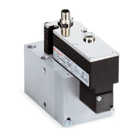
PROP-BLOCK
ADJUSTABLE PROPORTIONING VALVE & DISTRIBUTION BLOCK ALL-IN-ONE
A0730
A0730P
A0730PL
___________________________________________________________
Thank you for choosing STAINLESS STEEL BRAKES CORPORATION for your braking
needs. Pleases take the time to read and carefully follow these instructions to insure the ease of
your installation as well as the proper performance of the complete system.
Before beginning your installation, please verify you have received all the parts indicated on
the packing slip.
To assure your installation will go safely and smoothly, have the following items on hand to
assist you:
JACK & JACK STANDS WRENCH SET
LUG WRENCH TUBE WRENCHES
TORQUE WRENCH MALLET
SOCKET SET BRAKE FLUID
BRAKE CLEANER

1
A0730, A0730P, A0730PL Revision 2
A) Mounting
1) Select a suitable mounting location for the block assembly. In general, the necessary line
connections will be simpler with the block located near the master cylinder. If the vehicle has a
factory combination block bracket, the prop block can be mounted to that, otherwise the block
can be mounted to an inner fender or frame rail.
2) Secure the block using 5/16" hardware of the appropriate length for your specific application.
B) Line Connections
1) All of the in and out connections on the block are 3/8"-24 thread with an SAE flare for a standard
3/16" brake line. The supplied tube nuts can be flared onto any 3/16" brake lines; however, it is
not necessary to use these as long the lines you are using have a 3/8"-24 fitting already flared
on.
2) Connect the front brake outlet of the master cylinder to the port marked "F I" on the top of the
Prop Block. The outlet of the master cylinder for the front brakes will typically be the one for the
larger reservoir. If the reservoirs are the same size, a good rule of thumb is that the front
reservoir feeds the front brakes with GM master cylinders, while the rear reservoir feeds the front
brakes on Ford and Mopar master cylinders.
3) Next connect the two ports marked "F O" on the front and bottom of the Prop Block to the lines
feeding the front brakes of the vehicle. Most vehicles will have two separate brake lines: one
feeding the left (driver) front wheel and one feeding the right (passenger) front. If your vehicle
uses only one front brake line to feed both wheels, it is acceptable to plug the remaining front
outlet port of the Prop Block.
4) Connect the rear brake outlet port of the master cylinder to the port marked "R I" on the top of
the Prop Block.
5) Connect the port marked "R O" on the back of the Prop Block to the line feeding the rear brakes.
If your vehicle is equipped with a 1/4" rear brake line, use the supplied adapter fitting to connect
the line to the outlet of the prop block. SSBC has supplied the 1/4" adapter for the most popular
sizes. In the event that this fitting will not fit your line, you will need to locate a fitting from your
local parts store.
6) Tighten all fittings using a tube wrench and be sure to check for any leaks after the brake system
is bleed.
C) Switch Connections
1) The switch supplied with the Prop Block is a pressure switch designed to activate the brake lights
on the vehicle (and not the brake warning light on your dash). If your vehicle is equipped with a
brake light switch on the brake pedal, the switch in the Prop Block will not be used. If your vehicle
has no other brake light switch, then this switch must be properly connected for the brake lights
to function.
2) Your brake lights should already be connected to a chassis ground. The switch supplied will be
used to send power to the brake lights when pressure is applied to the brake system.
3) Connect the orange wire of the supplied pig tail to a fused constant 12V power supply. A 15-amp
circuit should be appropriate for most vehicles.
4) If your vehicle has separate circuits for the brake lights and turn signals, then the white wire of
the pig tail can be extended to the back of the vehicle and used to power the brake light pig tails
in the tail lights. If your vehicle uses the same circuit for brake lights and turn signals, then the
white wire will be run to your turn signal switch. Refer to the wiring diagram for your specific turn
signal switch for the proper connections.

2
A0730, A0730P, A0730PL Revision 2
D) Brake Bleeding
1) After the installation of the Prop Block is complete, it will be necessary to bleed the brake
system.
2) If the master cylinder is new or went dry at any time during the installation, begin by bench
bleeding the master cylinder.
3) Continue the bleeding process by gravity bleeding the caliper or wheel cylinder at each wheel
until no air bubbles are seen in the escaping brake fluid. Start with the wheel farthest from the
master cylinder and work your way closer bleeding each wheel. Never let the master cylinder go
dry at any time during this process.
4) With all the bleeding complete, a firm consistent pedal feel should be achieved. If the vehicle
already had a functioning brake system prior to the installation of the Prop Block, there should be
no significant change in the pedal feel.
5) With all bleeding complete, check all the fittings for leaks and tighten as necessary.
E) Proportioning Valve Adjustment
1) The proportioning valve in the Prop Block will be used to adjust the rear brake pressure of the
vehicle. The objective is to balance the pressure of the rear brakes to the front so that under hard
braking, the rear brakes do not lock up before the fronts.
2) Start with the valve in the full increase position by turning the knob all the way out in a clockwise
rotation.
3) Find a safe open area such as parking lot and make several hard stops from 30 M.P.H. observing
the function of the rear brakes. If the rear brakes lock up well before the front, begin to decrease
the rear brake pressure by turning the knob in a counter clockwise rotation. Continue these
adjustments until the proper balance is found.
4) When you have found the proper adjustment for your vehicle try the test again at 50 M.P.H. and
make any further adjustments as necessary.
DO NOT DRIVE IN TRAFFIC UNTIL THE BRAKES SAFELY STOP THE CAR IN A SAFE
DISTANCE WITHOUT A SPONGY PEDAL FEEL!
BRAKING TESTS SHOULD ALWAYS BE DONE IN A SAFE OPEN AREA!
NOW ENJOY TRUE PERFORMANCE BRAKING!

Shop for other Replacement Brake Parts on our website.
This manual suits for next models
2
Table of contents
Popular Control Unit manuals by other brands

Emerson
Emerson Anderson Greenwood 727 Series Installation and maintenance instructions
ICP DAS USA
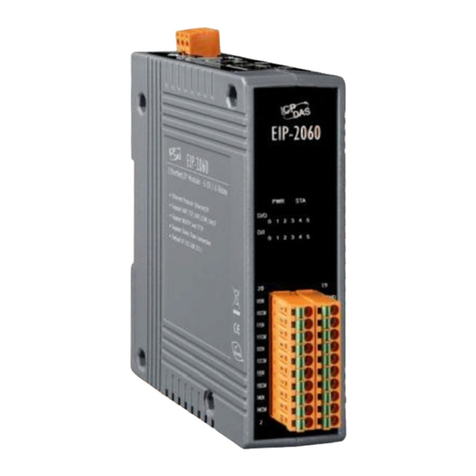
ICP DAS USA EIP-2060 quick start guide

AWG
AWG 30277633 instruction manual

Rothenberger
Rothenberger ROLOC PLUS Instructions for use

Bosch
Bosch Rexroth 2THE5R instruction manual
TRIGA
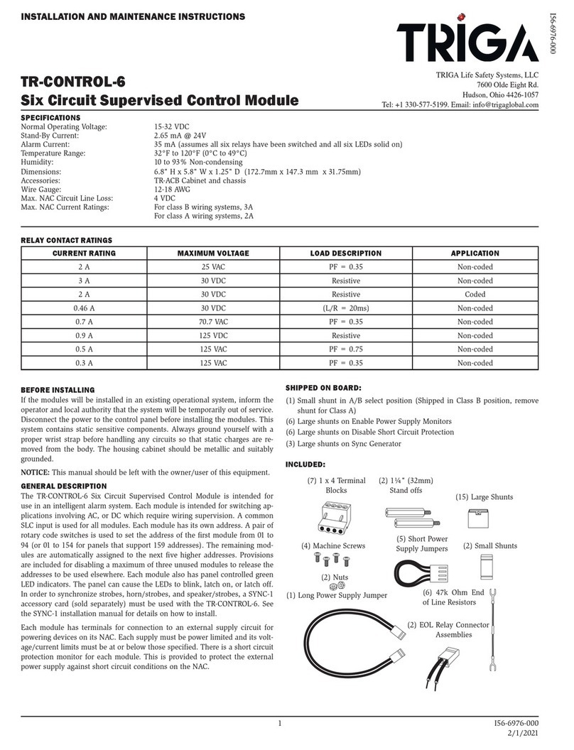
TRIGA TR-CONTROL-6 Installation and maintenance instructions
