SSD NEB/3U User manual
07-01-02-02-E-V0605.DOC
NEB/3U
Power supply
plug-in module
Product
Manual

________________________________________________________________________________________________________________________________________________________________________________________________________________________
2 Product Manual Type: NEB/3U 07-01-02-02-E-V0605.DOC
Further descriptions, that relate to this document:
UL:07-01-05-06
635 - Product Manual
UL:07-01-01-01
Rack 3U - Product Manual
©SSD Drives GmbH.
All rights reserved. No portion of this description may be produced or processed in any form without the
consent of the company.
Changes are subject to change without notice.
SSD Drives has registered in part trademark protection and legal protection of designs.
The handing over of the descriptions may not be construed as the transfer of any rights.
Made in Germany, 2005

________________________________________________________________________________________________________________________________________________________________________________________________________________________
07-01-02-02-E-V0605.DOC Product Manual Type: NEB/3U 3
CONTENTS
page
The most important thing first ..........................................................................4
1 Description................................................................................................5
2 Type code..................................................................................................6
2.1 Typical Example..............................................................................................................................6
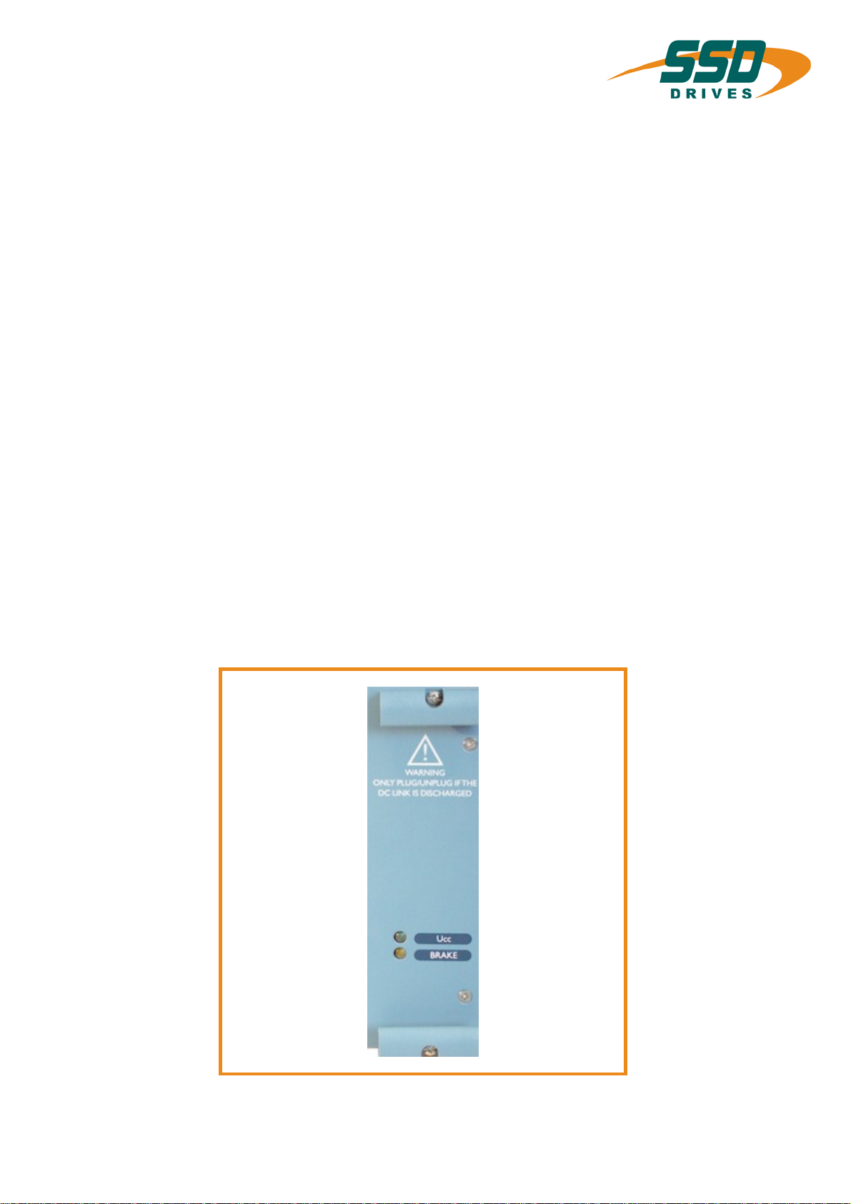
3 Front view, Power-supply plug-in module.............................................7
4 Technical data...........................................................................................8
5 Assignment / Power connectors.............................................................9
6 Miscellaneous.........................................................................................10
7 Adjustments............................................................................................11
7.1 The ballast power is adjusted in production! ................................................................................11
8 Fuses /Monitorings.................................................................................11
8.1 Fuse for overload protection.........................................................................................................11
8.2 Fuse for conducting path protection.............................................................................................11
8.3 Switching current limiting..............................................................................................................11
8.4 Ballast monitoring .........................................................................................................................11
9 Update list ...............................................................................................12

________________________________________________________________________________________________________________________________________________________________________________________________________________________
4 Product Manual Type: NEB/3U 07-01-02-02-E-V0605.DOC
The most important thing first
Thanks for your confidence choosing our product.
These operating instructions present themselves as an overview of the technical data and
features.
Please read the operating instructions before operating the product.
If you have any questions, please contact your nearest SSD Drives representative.
Improper application of the product in combination with dangerous voltage can lead to
injuries.
In addition, damage can also occur to motors or other products.
Therefore please observe our safety precautions strictly.
Safety precautions
We assume that, as an expert, you are familiar with the relevant safety regulations,
especially in accordance with VDE 0100, VDE 0113,VDE 0160, EN 50178, the accident
prevention regulations of the employers liability insurance company and the DIN
regulations and that you are able to use and apply them.
As well, relevant European Directives must be observed.
Depending on the kind of application, additional regulations e.g. UL, DIN are subject to be
observed.
If our products are operated in connection with components from other manufacturers,
their operating instructions are also subject to be observed strictly.

________________________________________________________________________________________________________________________________________________________________________________________________________________________
07-01-02-02-E-V0605.DOC Product Manual Type: NEB/3U 5
1 Description
The power-supply-plug-in module NEB/3 is connected to 1 or 3 * 230 V AC.
The device makes from the power-supply voltage the rated voltage of 325 V DC for the
intermediate circuit for the servo drive 635 from SSD Drives.
The power supply module is located extremely left in the rack.
The module can only be delivered with ballast circuit.
The ballast input power integrated in the power supply module is ventilated according to the
adjustment 30 W ... 55 W.
The power supply module can also be used for lower power supply voltages by changing the
resistance R 10, required for example when using DC-servo motors.
________________________________________________________________________________________________________________________________________________________________________________________________________________________
6 Product Manual Type: NEB/3U 07-01-02-02-E-V0605.DOC
2 Type code
Standard Specialr
Marking a b c d e f g
Type: NE B XX -XXX /3- XX -X
Marking Description
a NE = Plug-in power supply
b B= Ballast circuit
c Permanent current
10 = 10 Amperes
15 = 15 Amperes
25 = 25 Amperes
d Adjusted ballast input power:
-030 = 30 W internal, at 10 A continuous current - uncooled
-055 = 55 W internal, at 15 A continuous current - cooled
-(100) = 100 W external, at 25 A continuous current - uncooled or cooled
e Heights units:
/3 = 3 U (appr. 128,4mm)
f = Code adjusted ballast input power
A1 Details see chapter 7
A2
B2
C1
g Special:
b= Protection against condensation
c= Additional capacitors
total capacity 900 µF (standard: 450 µF)
h= b + c
The external ballast resistor is not included in the standard delivery ≅accessories
2.1 Typical Example
Example for ordering information corresponding to the type code:
NE B 10 -030 /3 A1
Code ballast input power
3U (appr. 128,4mm)
30W internal ballast input power
10Amperes continuous current
Ballast circuit
Plug-in power supply
________________________________________________________________________________________________________________________________________________________________________________________________________________________
07-01-02-02-E-V0605.DOC Product Manual Type: NEB/3U 7
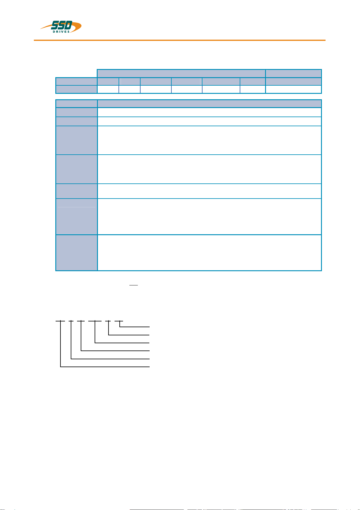
3 Front view, Power-supply plug-in module
Dimensions:
Width = approx. 40,0 mm (8 HP)
Hight = approx. 128,4 mm (3 U)
Depth = approx. 160,0 mm
plus jutting out H15 strip
Arrangement (standard):
left rack socket

________________________________________________________________________________________________________________________________________________________________________________________________________________________
8 Product Manual Type: NEB/3U 07-01-02-02-E-V0605.DOC
4 Technical data
Power-supply
plug-in modu: Module
width Output current Adjusted
ballast input power Ohmic resistance
of the ballast
Type not ventilated * ventilated int. ext. resistance
(-) (HP) (A) (A) (W) (-) (-) (Ω)
NEB 10-030/3 -A1 8 10 25 30 x - 54
NEB 15-055/3 -B2 8 - 15 55 x - 54
NEB 25-(100)/3 -A2 8 25 25 100 - x 33
NEB 25-(100)/3- C1 8 25 25 100 - x 22
Specifications concerning supply voltage 230 V AC!
* Fan: L220 K
Air flow rate 80 m³ / h,
Supply voltage 230 V / 50 Hz
General data minimum nominal maximum dimension
Power connector - 230 255 Veff
Mains frequency 45 50 60 Hz
Feed-in 3-phase or 1-phase
Output voltage: - 325 360 V DC Ucc
Ballast res. On 370 376 380 V DC Ub
Ballast res. Off - - 370 V DC Ub
Mounting position: vertical in free stream of air 150 mm free
space towards the bottom and the top
Weight: 0,5 kg
Type of protection: IP 00 according to DIN 40 050
Permissible ambient temperature:
¾Operation: 0°C ... + 40°C
¾in case of power reduction: up to + 55°C
¾storage and transport: - 25°C ... + 85°C

________________________________________________________________________________________________________________________________________________________________________________________________________________________
07-01-02-02-E-V0605.DOC Product Manual Type: NEB/3U 9
5 Assignment / Power connectors
View from the rear of the rack:
Clamps Function descriptin
4 +Ucc
6 +Ucc
8 +Ucc
DC - bus voltage
10 L1
12 L1
14 L2
16 L2
18 L3
20 L3
Supply voltage
1* or 3* 230 V AC
22 -Ucc
24 -Ucc
26 -Ucc
DC bus voltage
28 +RB
30 -RBExternal
Ballast resistor
32 GND Ground
Attention:
With 1-phase connection clamps 14 and 16 are used as zero conductors "N".
________________________________________________________________________________________________________________________________________________________________________________________________________________________
10 Product Manual Type: NEB/3U 07-01-02-02-E-V0605.DOC
6 Miscellaneous
Guarantee:
Only when using original SSD Drives component racks, drives and ballast resistors SSD Drives guarantees
for 1 years .
Plug in and out the module:
The module may only be plugged in i.e. out when there is no voltage.
Attention:
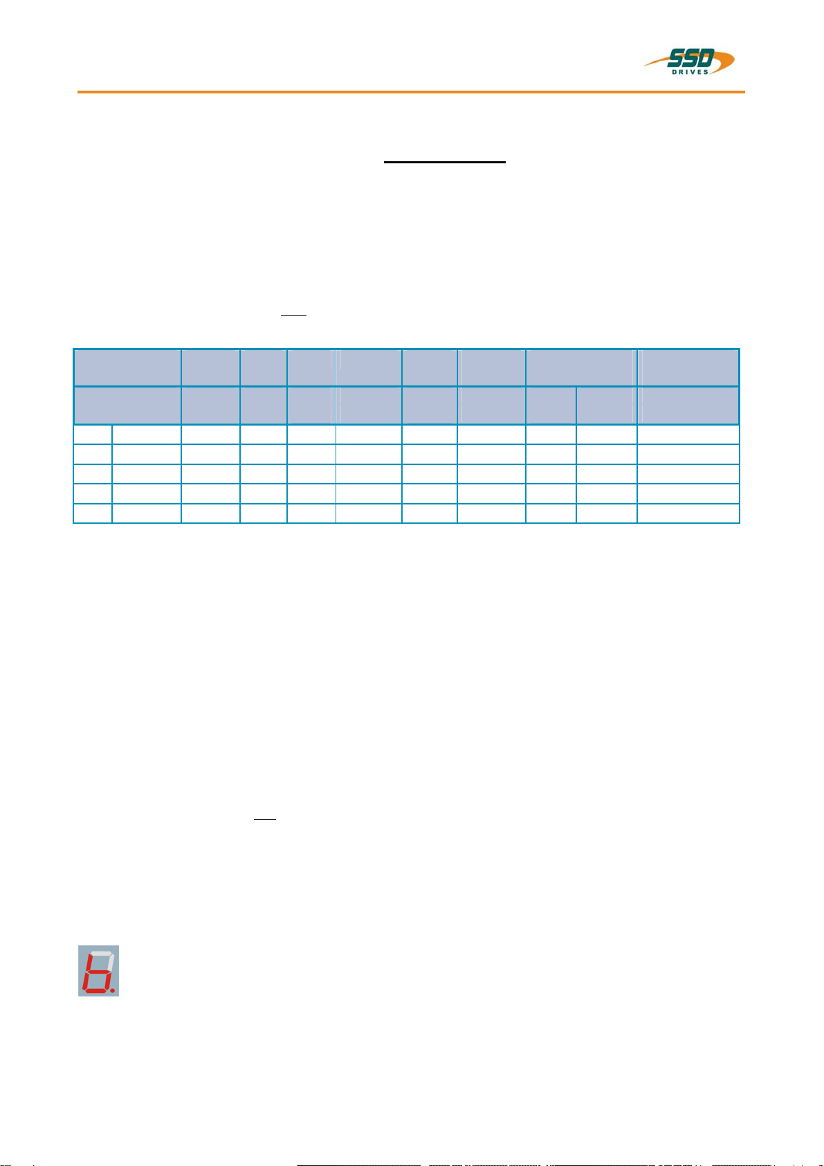
The power-supply plug-in module may only be plugged out 30
seconds after the green LED "Ucc ok", mounted on the front, is
out. (Discharge time of the capacitor)
ISO 9001:
The devices are produced in accordance with DIN ISO 9001.
All devices are subject to a 100% final test.
VDE-guidelines:
The device meets the requirements of the VDE 0100 and VDE 0160.
EG-certificate of conformity given for:
EN 50 081-2 interference emission high frequency emission
pr EN 50 082-2 immunity to interference against HF and impulses
vfg 242/1991 "barrage" jammer
The low-voltage guidelines are not met yet.
further information see:
•EG-certificate of conformity 16.7.1.2 and
•Enclosure I.1 to the EG-certificate of conformity 16.7.1.2
________________________________________________________________________________________________________________________________________________________________________________________________________________________
07-01-02-02-E-V0605.DOC Product Manual Type: NEB/3U 11
7 Adjustments
7.1 The ballast power is adjusted in production!
Adjustment via the solder jumpers JP4 and JP7 as well as the bridge RBinternal.
The jumpers are on the outside of the circuit board!
The bridge RBinternal is above the power connector between the two internal ballast resistors.
The total connection resistance may not fall below 20Ω.
JP4: ballast monitoring inactive only adjusted in production!
JP7: adjustment of the ballast power see table below
Design: Bridge
at RBJumper Ballast
power Resistance
value Supply unit
with sep. fan
R27 R27.1 JP 7 ΣR PwRw
- - (K Ω) (Ω) (W) (Ω) -
A 1 standard open ∞220 open 30 54 internal -
A 2 standard open ∞220 closed 220 100 33 external -
B 2 standard closed ∞220 closed 220 55 54 internal x
C 1 special open 470 220 open 470 100 22 external -
C 2 special open 470 160 closed 120 200 22 external -
8 Fuses /Monitorings
8.1 Fuse for overload protection
F100 - intermediate circuit / overload
- 30A slow-acting
8.2 Fuse for conducting path protection
FB1 - ballast circuit/ conducting path protection
- 10 A slow-acting
8.3 Switching current limiting
Surge-Gard R50 for switching current limiting
With operation of the supply unit via 15 A (NEB25) Inenn the solder jumper is closed in production!
This solder jumper is on the side of the etched conductor of R50.
Consequently the switching current limiting is inactive.
If required the customer has to make sure that there is an external switching current limiting.
8.4 Ballast monitoring
If the returned electric energy lets rise the voltage of the intermediate circuit above 385 V DC when braking,
the corresponding drive switches off in dependence of the drive tolerance (+/- 5 %) with error message
= "over voltage at DC-bus".
Further information see 635 drive documentation (07-01-05-06-D-Vxx )

________________________________________________________________________________________________________________________________________________________________________________________________________________________
12 Product Manual Type: NEB/3U 07-01-02-02-E-V0605.DOC
9 Update list
Version Amendment Chapter Date Name Remarks
V05.16EHST96 None 11.03.99 K. Stadler ET-design
V0605 separate German / all
Logos
English
SSD Drives 18.02.05 N. Dreilich

Argentina · Bangladesh · Brazil · Chile · Colombia Costa Rica Czech Republic · Ecuador · Greece · Hungary
ndonesia Iceland · Israel Kuwait · Lithuania · Malaysia · Marocco · Mexico · New Zealand · Nigeria · Peru · Philippines · Portugal
Saudi Arabia · Singapore · Slovenia · Sri Lanka · South Africa · Taiwan · Thailand · Turkey · United Arab Emirates · Vietnam
Austria · · · Cyprus · ·
I · ·
Local availability and service support also in:
United Kingdom
SSD Drives Ltd
New Courtwick Lane
Littlehampton
West Sussex BN17 7RZ
:
Fax:
Tel +44 1903 737000
+44 1903 737100
AUSTRALIA
Eurotherm Pty Ltd
Unit 1
20-22 Foundry Road
Seven Hills
New South Wales 2147
Tel:
Fax:
+61 2 9838 0099
+61 2 9838 9288
DENEMARK
SSD Drives
Enghavevej 11
DK-7100 Vejle
:
Fax:
Tel +45 70 201311
+45 70 201312
CANADA
SSD Drives Inc
880 Laurentian Drive
Burlington
Ontario
Canada, L7N 3V6
:
Fax:
Tel +1 905 333-7787
+1 905 632-0107
KOREA
SSD Korea Co., Ltd.
1308, Daeryung Techno Town
8th Bldg., 481-11 Gasan-Dong,
Geumcheon-Gu,
Seoul 153-803
:
Fax:
Tel +82 2 2163 6677
+82 2 2163 8982
NETHERLANDS
Eurotherm BV
Genielaan 4
2404CH
Alphen aan den Rijn
:
Fax:
Tel +31 172 411 752
+31 172 417 260
Poland
OBR-USN
ul. Batorego 107
PL 87-100 Torun
:
Fax:
Tel +48 56 62340-21
+48 56 62344-25
SPAN
Eurotherm Espana S.A.
Pol. Ind. Alcobendas
C/ La Granja, 74
28108 Madrid
:
Fax:
Tel +34 91 661 60 01
+34 91 661 90 93
SCHWEDEN
SSD Drives AB
Montörgatan 7
S-30260 Halmstad
:
Fax:
Tel +46 35 177300
+46 35 108407
SWITZERLAND
Indur Antriebstechnik AG
Margarethenstraße 87
CH 4008 Basel
:
Fax:
Tel +41 61 27929-00
+41 61 27929-10
U.S.A
SSD Drives Inc.
9225 Forsyth Park Drive
Charlotte
North Carolina 28273-3884
:
Fax:
Tel +1 704 588 3246
+1 704 588 3249
CHINA
Eurotherm Pty Ltd
Apt. 1805, 8 Building Hua Wei Li
Chao Yang District,
Beijing 100021
:
Fax:
Tel +86 10 87785520
+86 10 87790272
GERMANY
SSD DRIVES GmbH
Von-Humboldt-Straße 10
64646 Heppenheim
:
Fax:
Tel +49 6252 7982-00
+49 6252 7982-05
FRANCE
SSD Drives SAS
15 Avenue de Norvège
Villebon sur Yvette
91953 Courtaboeuf Cedex / Paris
:
Fax:
Tel +33 1 69 185151
+33 1 69 185159
HONG KONG
Eurotherm Ltd
Unit D
18/F Gee Chang Hong Centre
65 Wong Chuk Hang Road
Aberdeen
:
Fax:
Tel +852 2873 3826
+852 2870 0148
INDIA
Eurotherm DEL India Ltd
152, Developed Plots Estate
Perungudi
Chennai 600 096, India
:
Fax:
Tel +91 44 2496 1129
+91 44 2496 1831
IRELAND
SSD Drives
2004/4 Orchard Ave
Citywest Business Park
Naas Rd, Dublin 24
:
Fax:
Tel +353 1 4691800
+353 1 4691300
ITALY
SSD Drives SpA
Via Gran Sasso 9
20030 Lentate Sul Seveso
Milano
:
Fax:
Tel +39 0362 557308
+39 0362 557312
JAPAN
PTI Japan Ltd
7F, Yurakucho Building
10-1, Yuakucho 1-Chome
Chiyoda-ku, Tokyo 100-0006
:
Fax:
Tel +81 3 32132111
+81 3 32131900
Romania
Servosisteme SRL
Sibiu 17
061535 Bukarest
:
Fax:
Tel +40 723348999
+40 214131290
SSD Drives GmbH
Plant Servosystems
Im Sand 14, D-76669 Bad Schönborn
Telefon +49 (0)7253 9404-0, Fax +49 (0)7253 9404-99
·
Head Office
Von-Humboldt-Straße 10, D-64646 Heppenheim
Telefon +49 (0)6252 7982-00, Fax +49 (0)6252 7982-05
www.SSDdrives.com [email protected]
Table of contents
Popular Power Supply manuals by other brands


PS Audio
PS Audio PerfectWave Power Plant 5 Owner reference guide

Sony
Sony DC-V700 operating instructions

Clayton Power
Clayton Power LPS II Series Manual and safety instructions

City Theatrical
City Theatrical PDS-750 TRX user manual

AMI
AMI 4Q06125PS-430 Installation, operation and maintenance instructions

Seiko Epson
Seiko Epson OT-BX220 installation manual


