http://www.ce-transducer.com 3rdFloor,building1, Zaimaoindustrialpark, Baoji road, Bantian, Longgangdistrict,
sales@ce-transducer.com ShenzhenCity, ChinaPostcode:518049
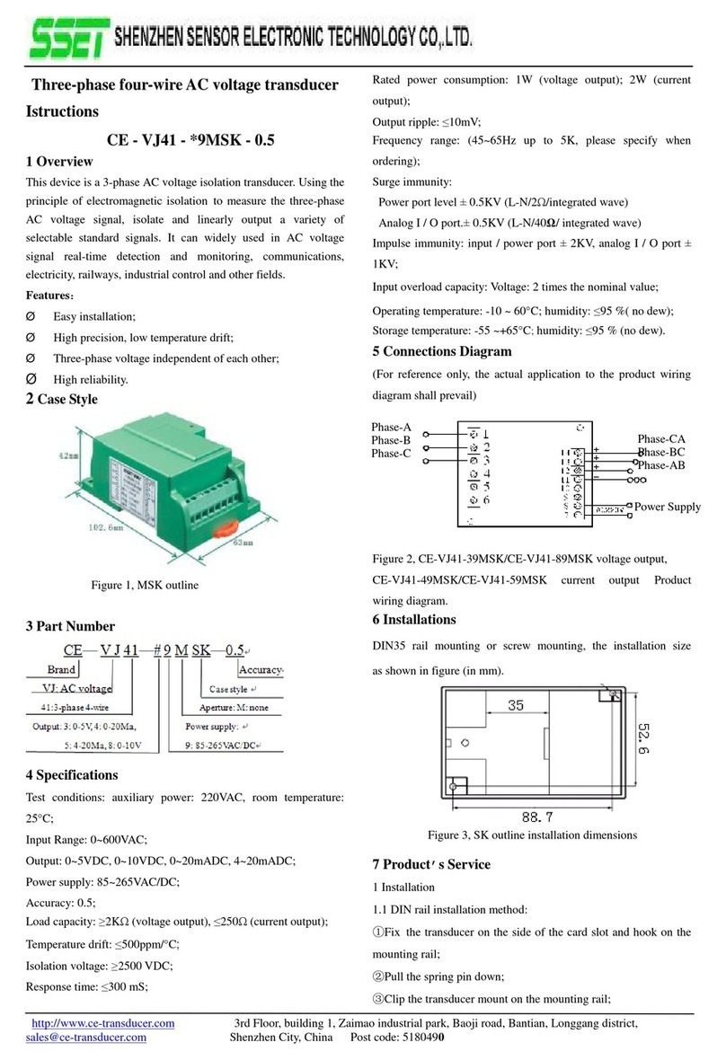
Figure4,SKcase installationdimensions
7 Product sService
1Installation
1.1DIN railinstallationmethod:
①Thetransducerfixedon thesideofthecardslotand hookonthe
mountingrail;
②Pull thespringpindown;
③Clipthetransducermounton themountingrail;
④Release thespringpinandclipthetransmitteron themounting
rail.
1.2Screwmountingmethod:
①4mmdiameterholeinthefixedplateaccordingtothescrew
holepositionshowninFig.8;
②Use thescrewsmallerthan Φ3.5toinsert intoholetosecureit.
2Producthas beenaccuratelysetaccordingtothe"product
standard".Applypowerafterdeterminethecorrectwiring.
3Themaximumwirediameteroftheterminalblockis1.3mm
(16-26AWG).Removethe4mm~5mminsulationlayerfromthe
end ofthemountingwireand insert it intotheterminalblock.
Tightenthescrew.
4Productsupplypowerrequires theisolationvoltage ≥2000VAC,
ACripple<10mV.Multipletransducerscanshareacommon set
ofpowersupplies,butthepowercircuit canno longerbeusedto
driverelaysand othercanproduce spikes intheload,inorderto
avoidinterference signaltransmission tothetransducer.
5 Thetransducersoutput0-20mA(or4-20mA),theRLstandardis
250Ω,and 0-5VvoltageoutputRLstandardis ≥2KΩ,can
guarantee theoutputaccuracyand linearityovertheentire
ratedinputrange.
8 Example ofproductaccuracy levelverification
1Accordingtothetransducerterminaldefinition,connectthe
experimentalcircuit as shown.
Figure5, accuracytestwiringdiagramofthevoltageoutput
Figure6, accuracytestwiringdiagramofthecurrentoutput
Note:ThevoltageoutputismeasuredwithaVometerand the
currentoutputismeasuredwithanIometer.
2Thetestshall becarriedoutunderthefollowingenvironmental
conditions:
ØPowersupply:nominal ±5%, ripple 10mV;
ØAmbienttemperature:25 ℃±5 ℃;
ØRelativehumidity:RH (45 ~80)%;
ØTheaccuracyofthesignalsource and measuring
instrumentsis0.05class above.
3Powerpreheat2min;
4CurrentIinputandmonitoringmethods:
①Ahigh-precisionhigh-currentmetercalibratorcandirectly
inputACcurrentI,andrecordthedisplaydataofthemeter
calibrationinstrument.
②Nohigh-currenthigh-precisioninstrumentcalibrator,butthere
isaordinaryhigh-precisioninstrumentcalibrator.Use
ampere-turnmethodtooutputsmall current(5A,10Aorhigher),
and inputit tothetransducerinputcoil.Theprecision ammeteris
tandemconnection tothecalibratoroutputend todetectinput
current,andconvert theinputcurrentIvalueaccordingtothe
ampere-turnmethod.
5Assumingthatthetransducerinputis0-300AAC, theoutputis
0-5VDC, GiveaninputvalueI,withintherangeofthetransducer,
theexpectedtheoreticaloutput(Vz)ofthetransduceriscalculated
as follows:
Vz=I÷300×5V
Iftheoutputis0-10V, Vd=I÷30×10V.
Iftheoutputis4-20mA, thenIy=4+I÷300×16Ma.
Iftheoutputis0-20mA, thenIz=I÷300×20mA.
6MeasuretheDC voltageoutputvalueVoorthecurrentoutput
valueIowiththeoutputmonitoringtableand calculatetheerror
betweenthemand thestandardvalueaccordingtothefollowing
correspondingformula:
│Vo-Vt│ 25mVfornormal, orexcessive(0-5Voutput,0.5);
│Vo-Vd│ 50mVfornormal, orexcessive(0-10Voutput, 0.5);
Powersupply
Power
Source
Power
Powersupply

